Technical description
Corrosion protection KX according LV P1.001 for SAUDI ARAMCO Projects
Technical description
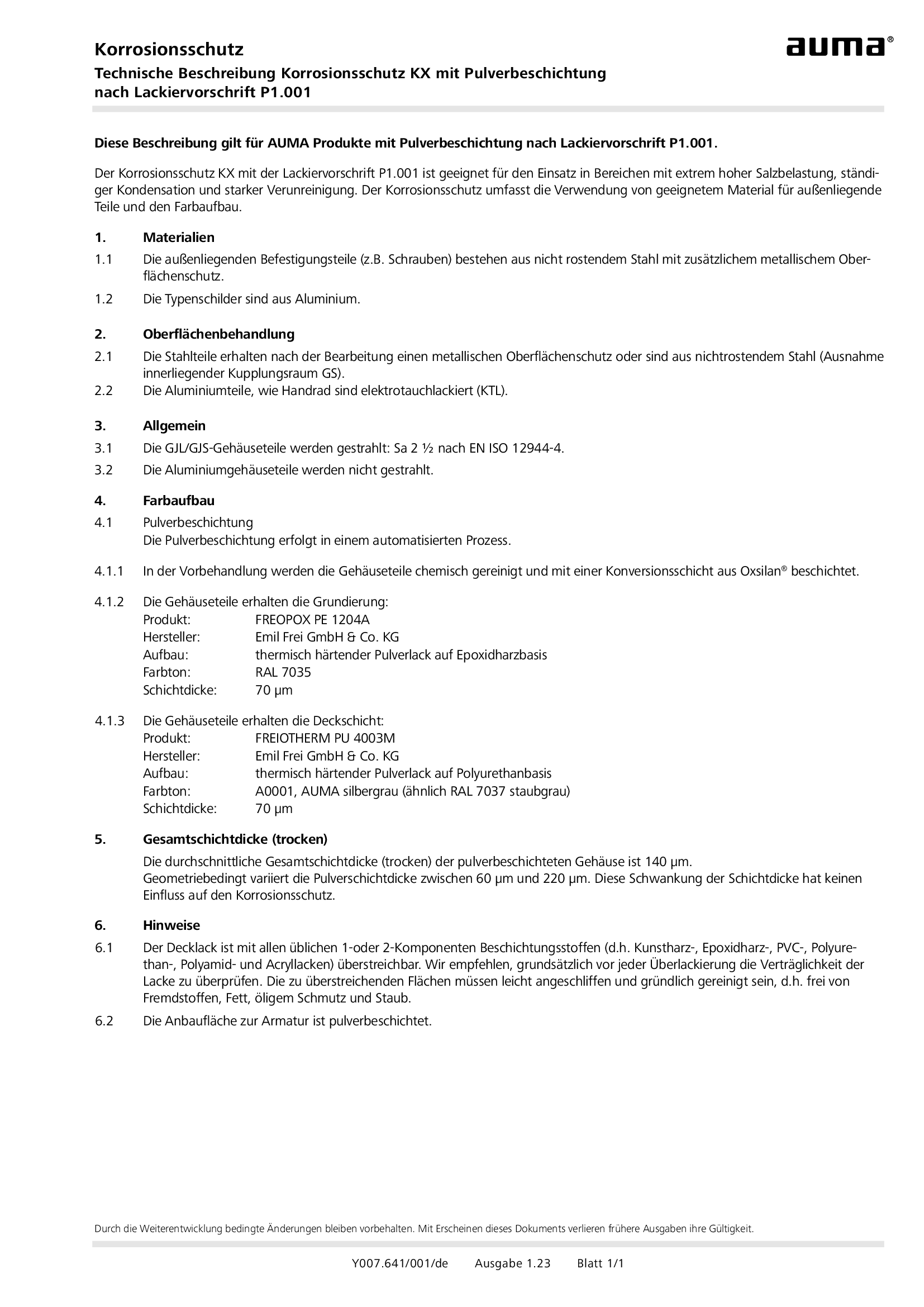
Corrosion protection KX with LV P1.001
Technical description
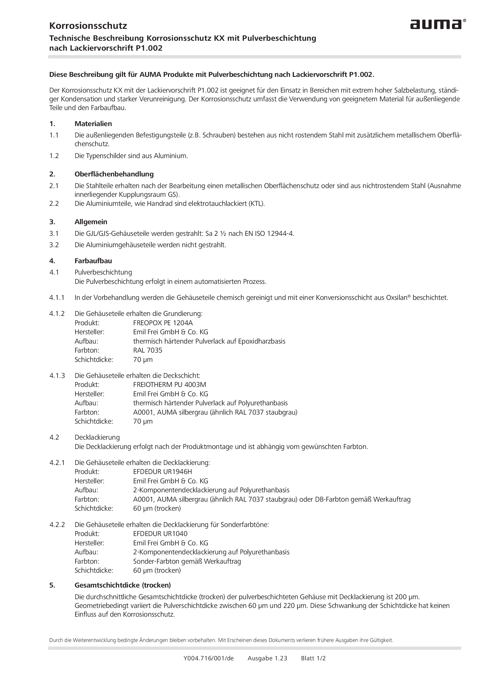
Corrosion protection KX with LV P1.002
Technical description
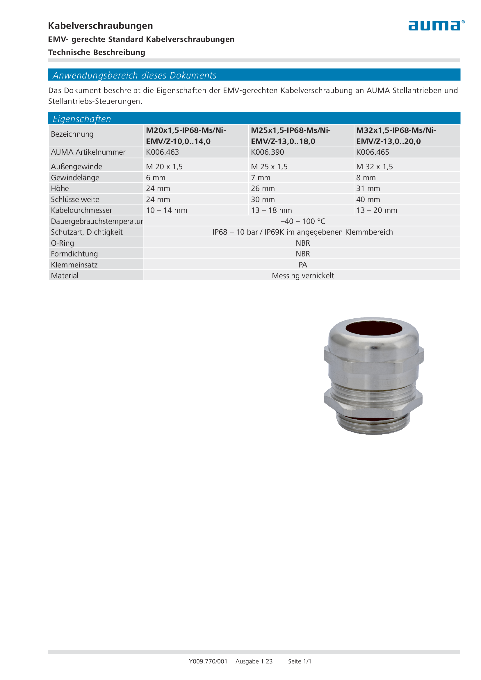
EMC approved standard cable glands
Technical description
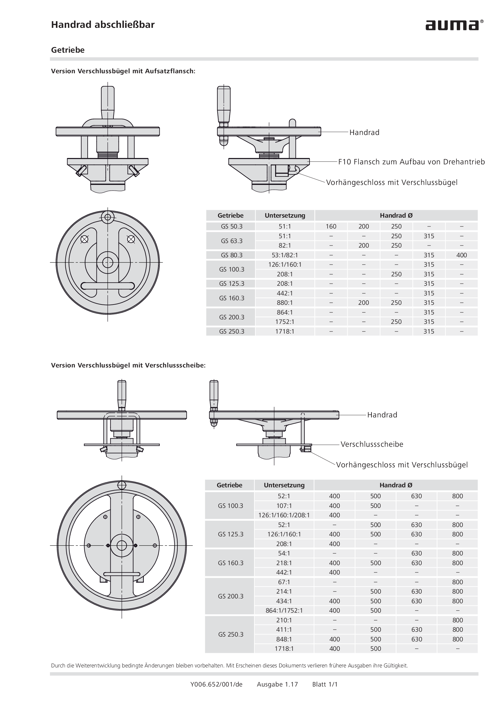
Handwheel lockable gearboxes GS 50.3 – GS 250.3, GF 50.3 – GF 250.3
Technical description
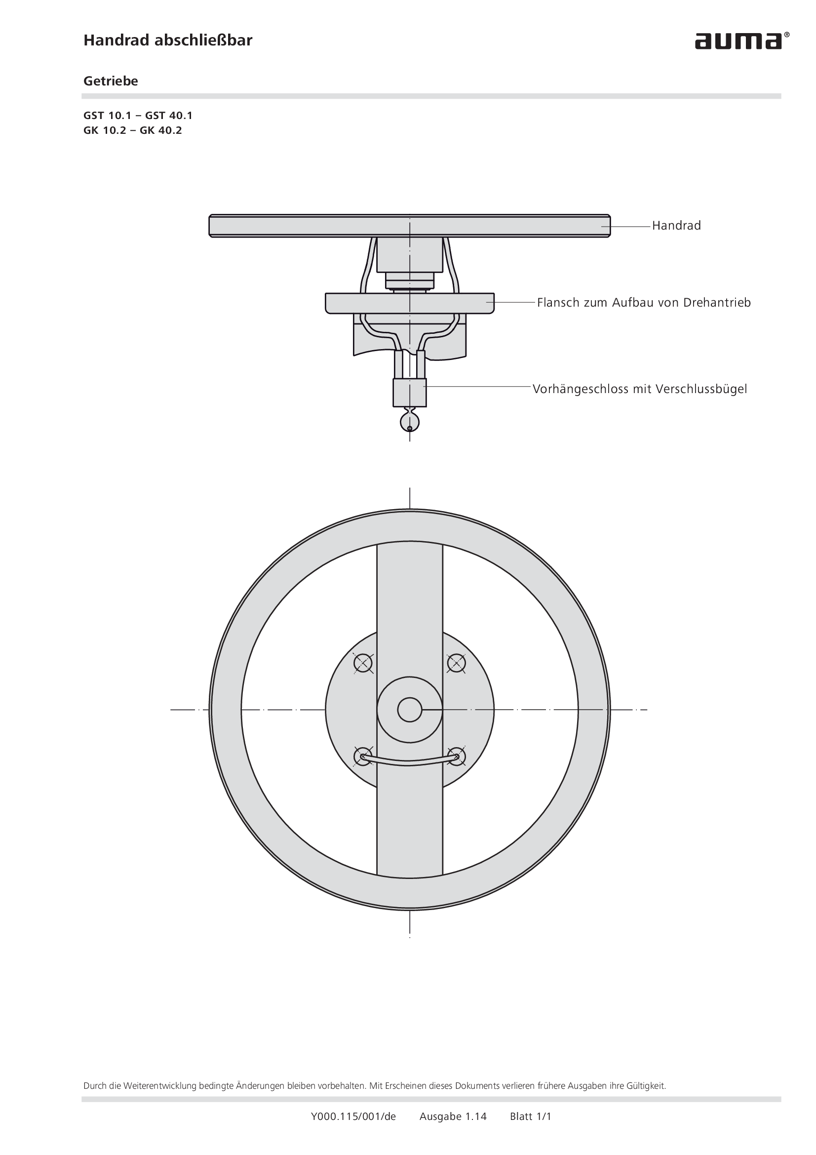
Handwheel lockable gearboxes GST 10.1 – GST 40.1, GK 10.2 – GK 40.2
Technical description
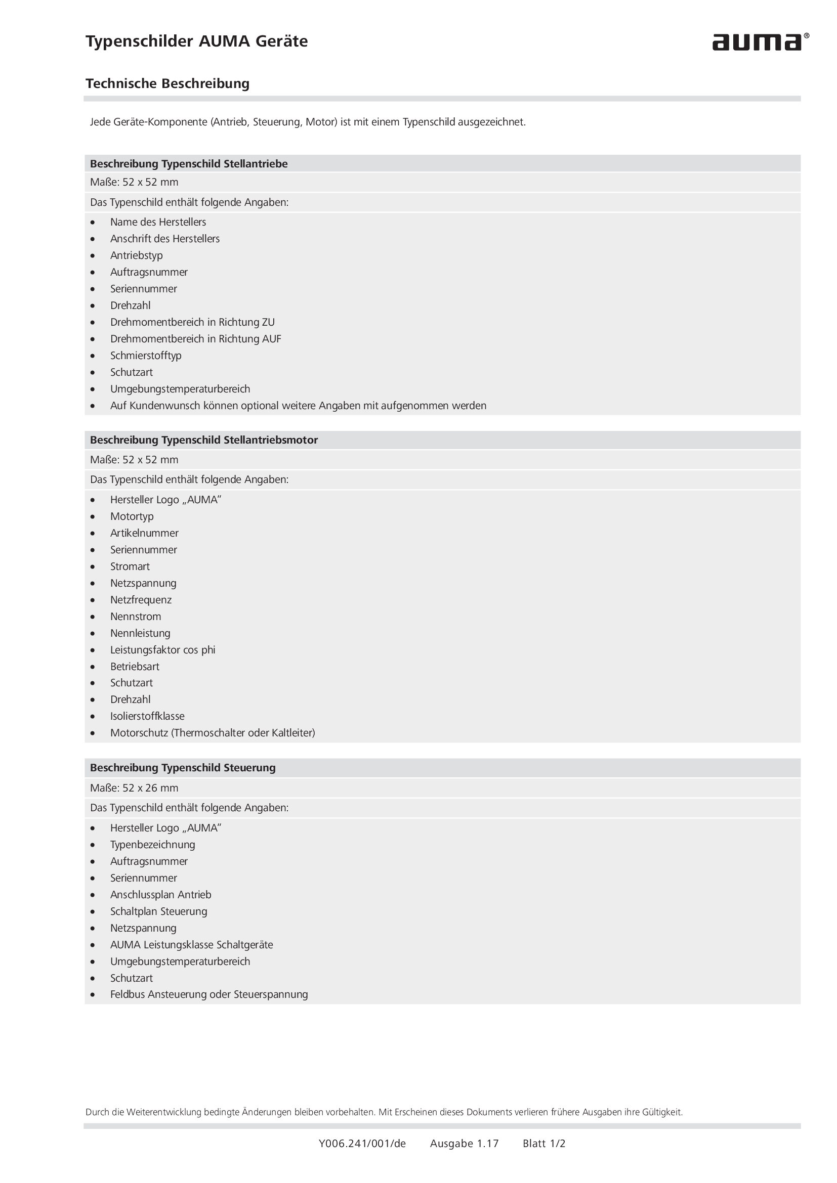
Name plates AUMA devices
Technical description
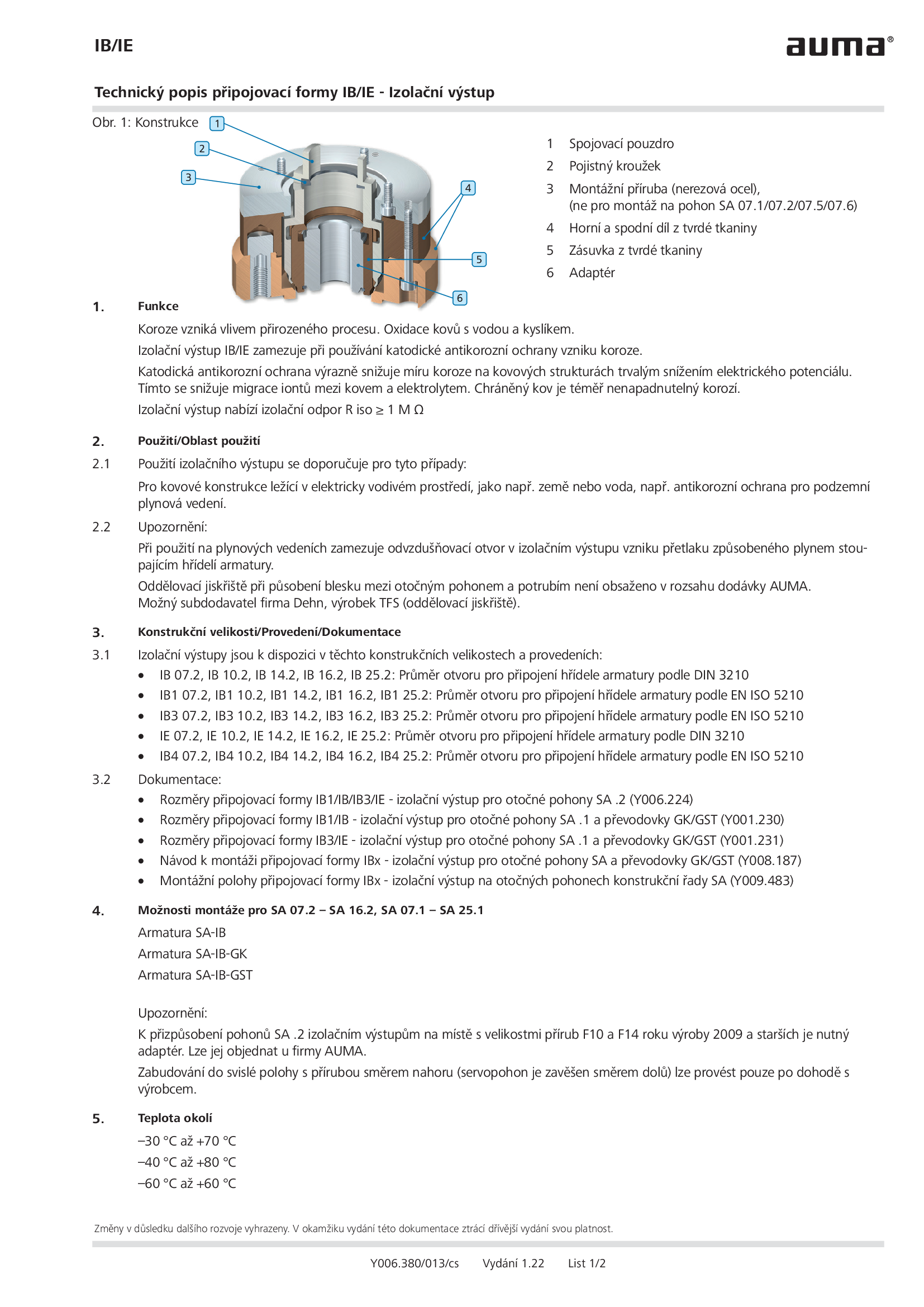
Output drive type IB/IE - Insulated output drive
Technical description
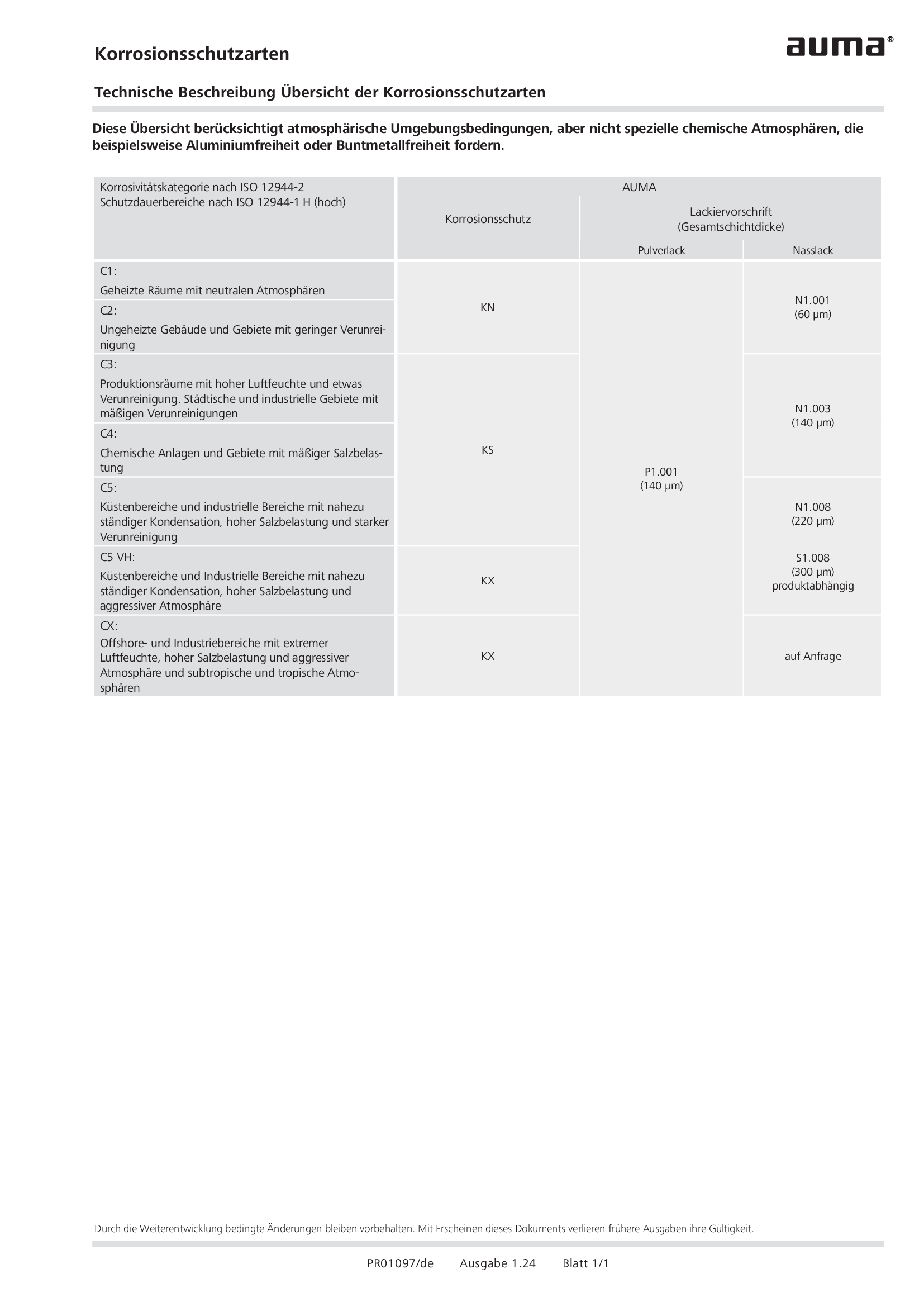
Overview Corrosion protection types
Technical description
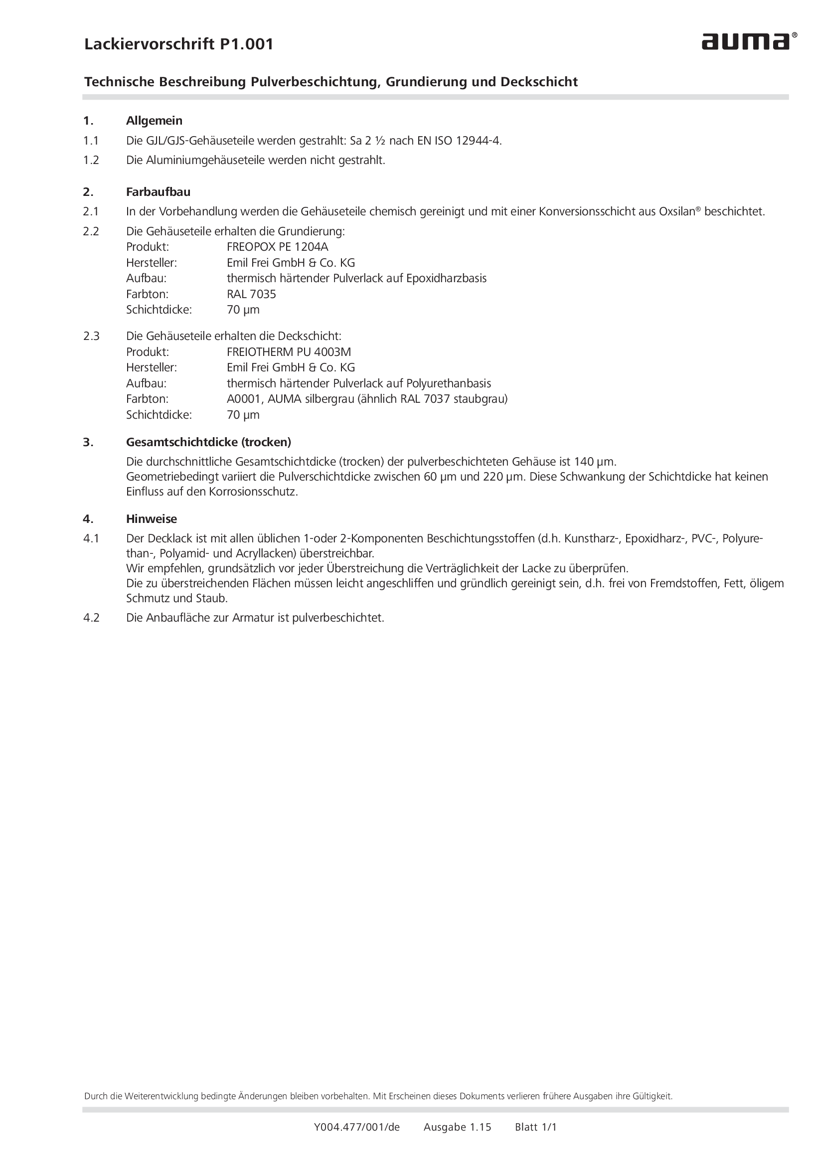
Painting specification P1.001 Powder coating, primer coating and finsh coating
Technical description
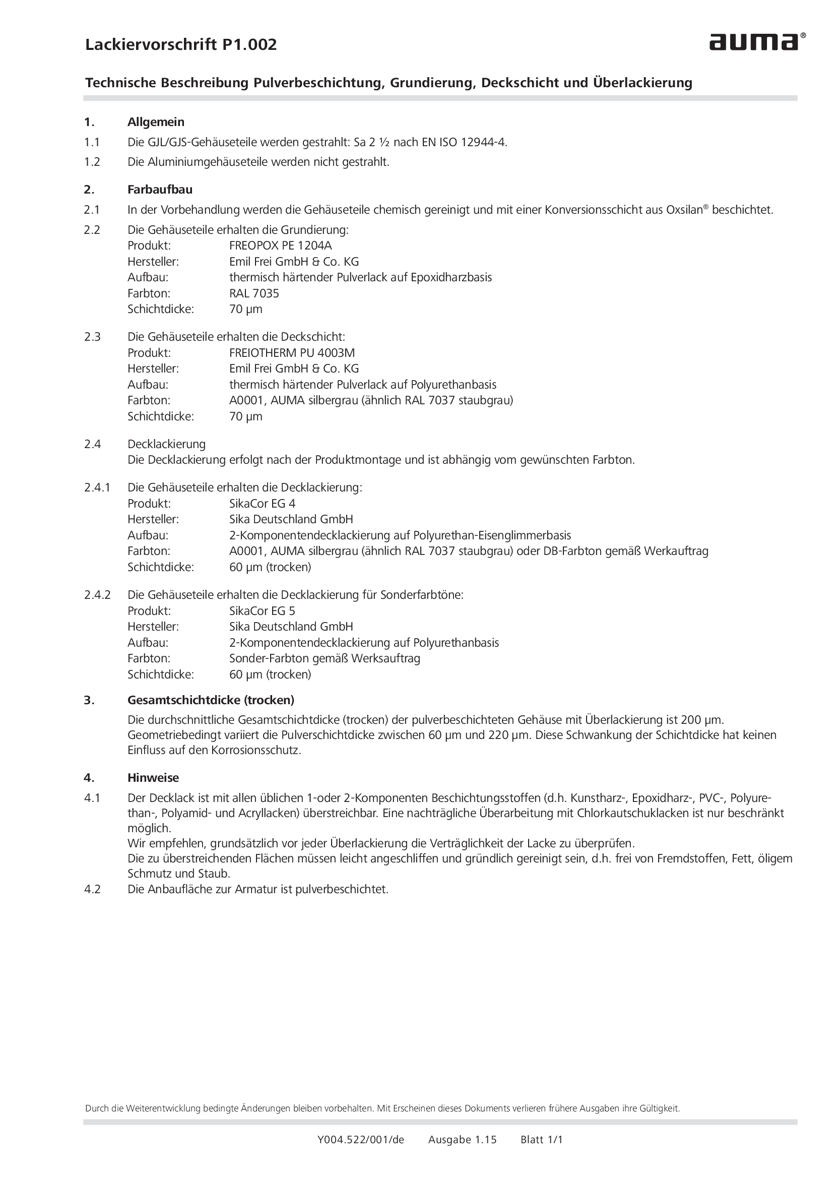
Painting specification P1.002 Powder coating, primer coating, finish coating and additional painting
Technical description
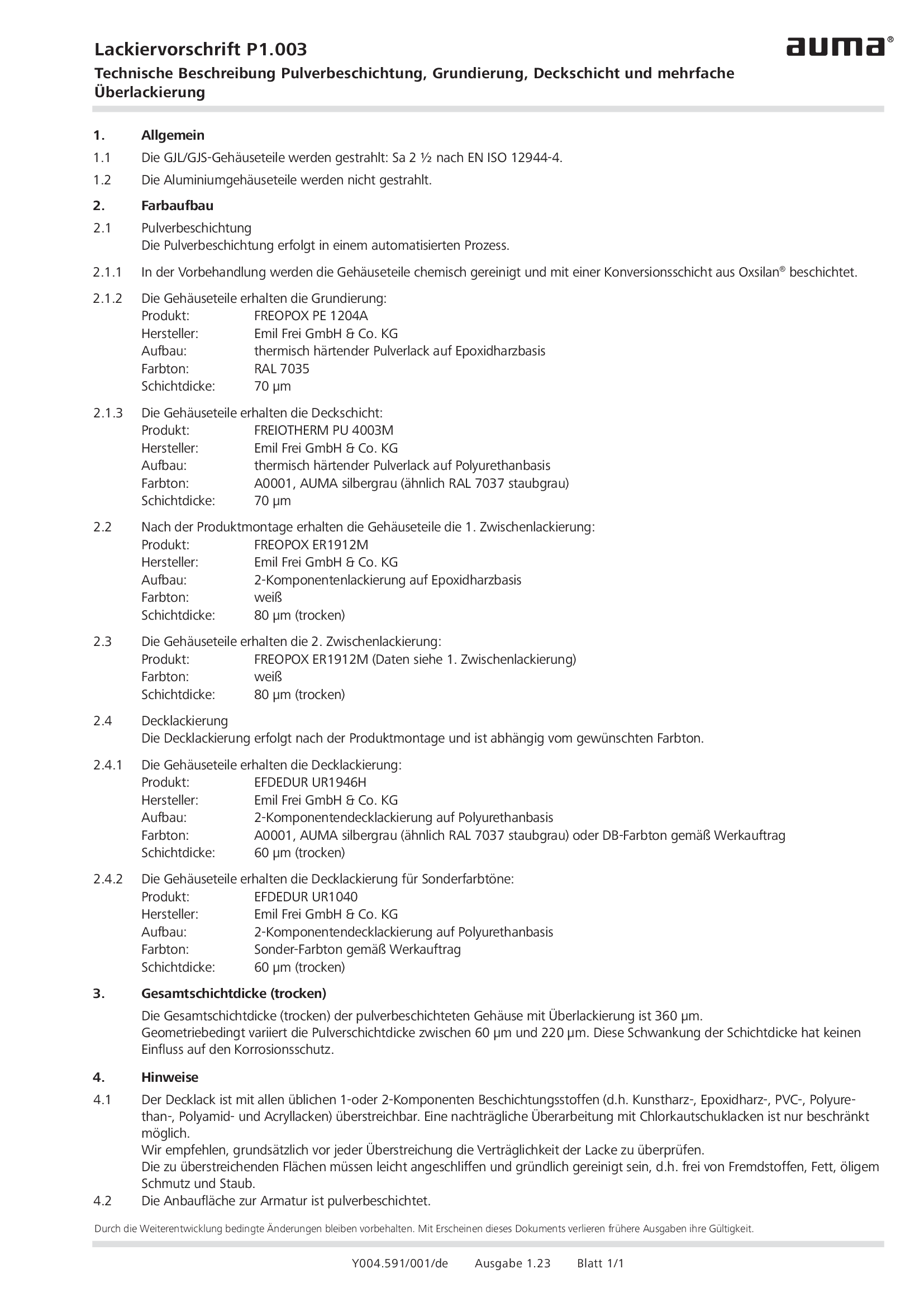
Painting specification P1.003 Powder coating, primer coating, finish coating and multi-layer painting
Technical description
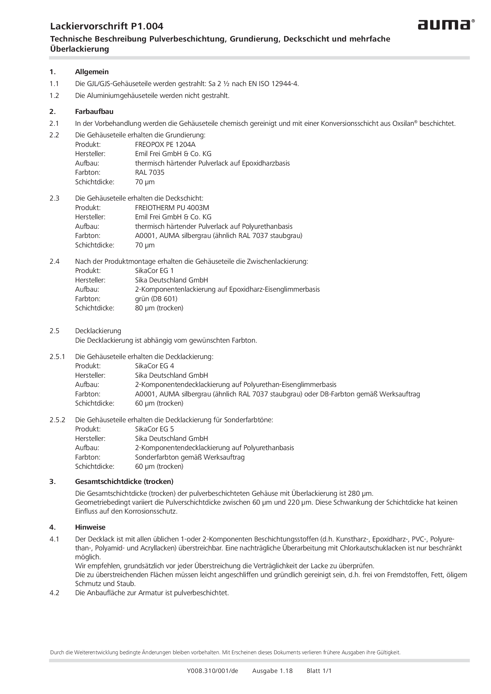
Painting specification P1.004 Powder coating, primer coating, finish coating and multi-layer painting
Technical description
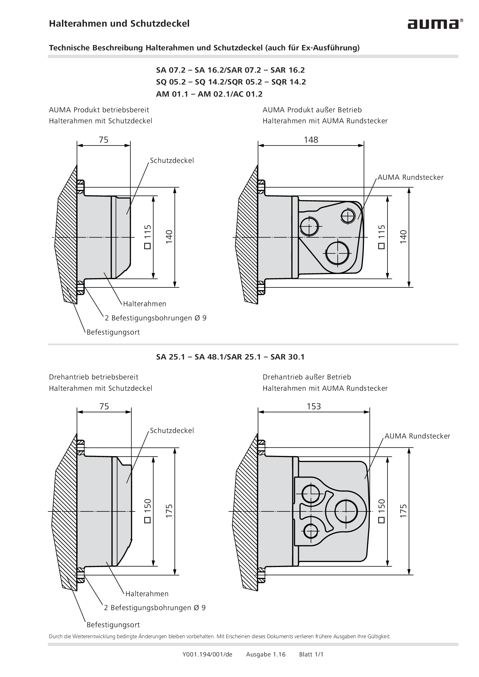
Parking frame and protection cover
Technical description

Position indicator with telescope protection tube
Technical description
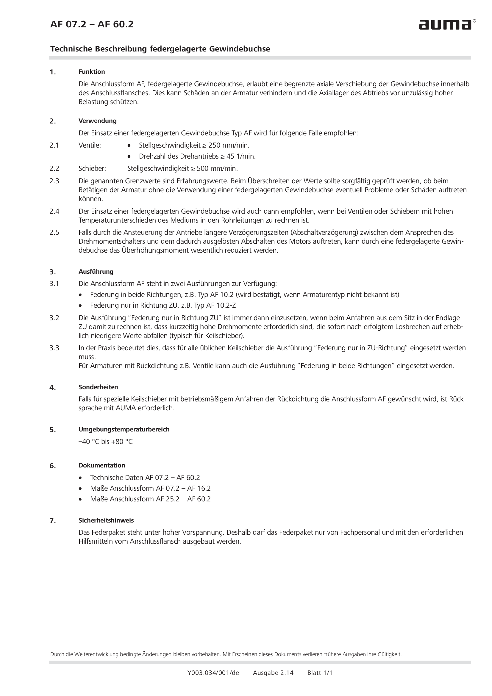
Spring loaded stem nut AF 07.2 - 60.2
Technical description
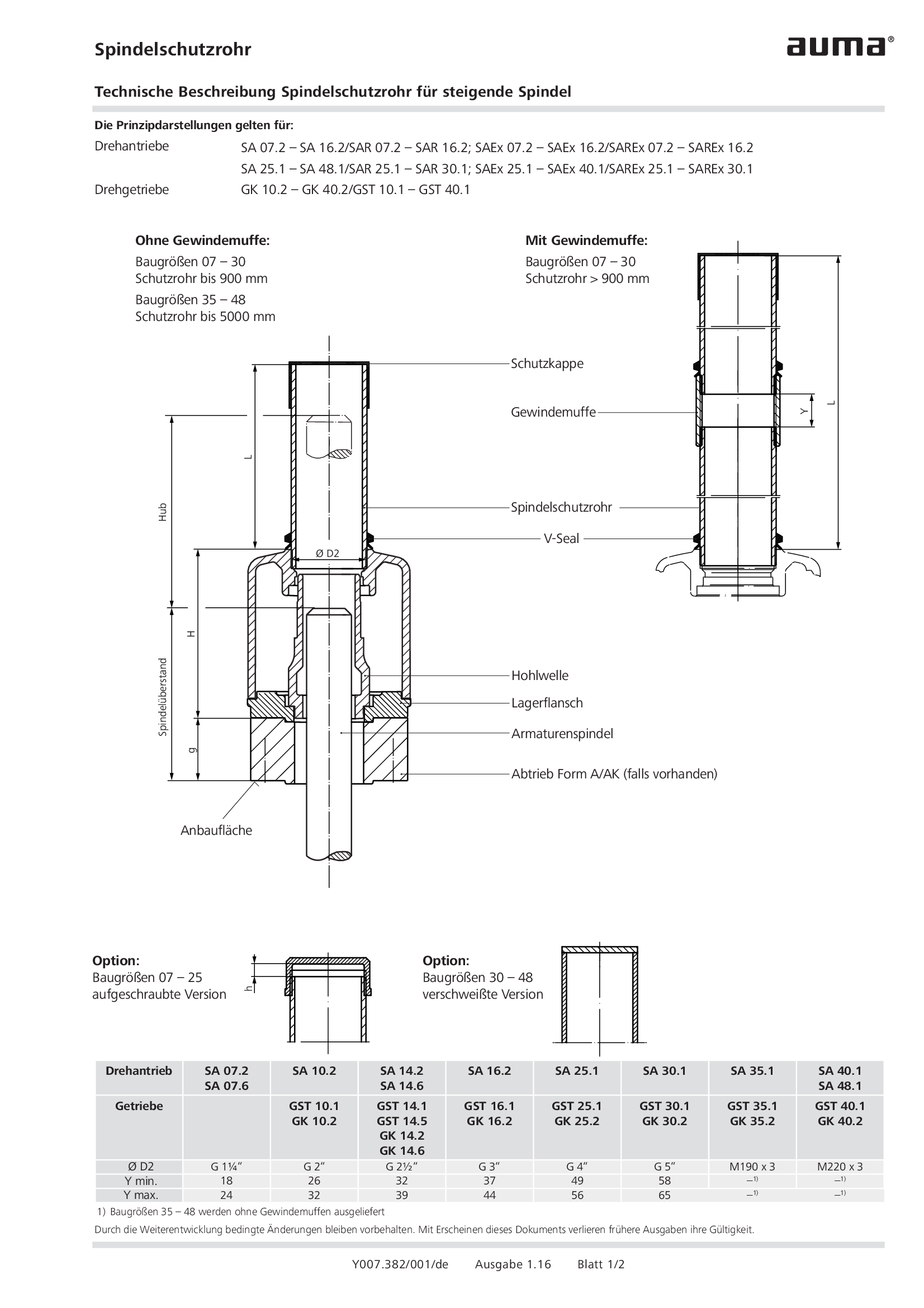
Stem protection tube for rising stem
Technical description
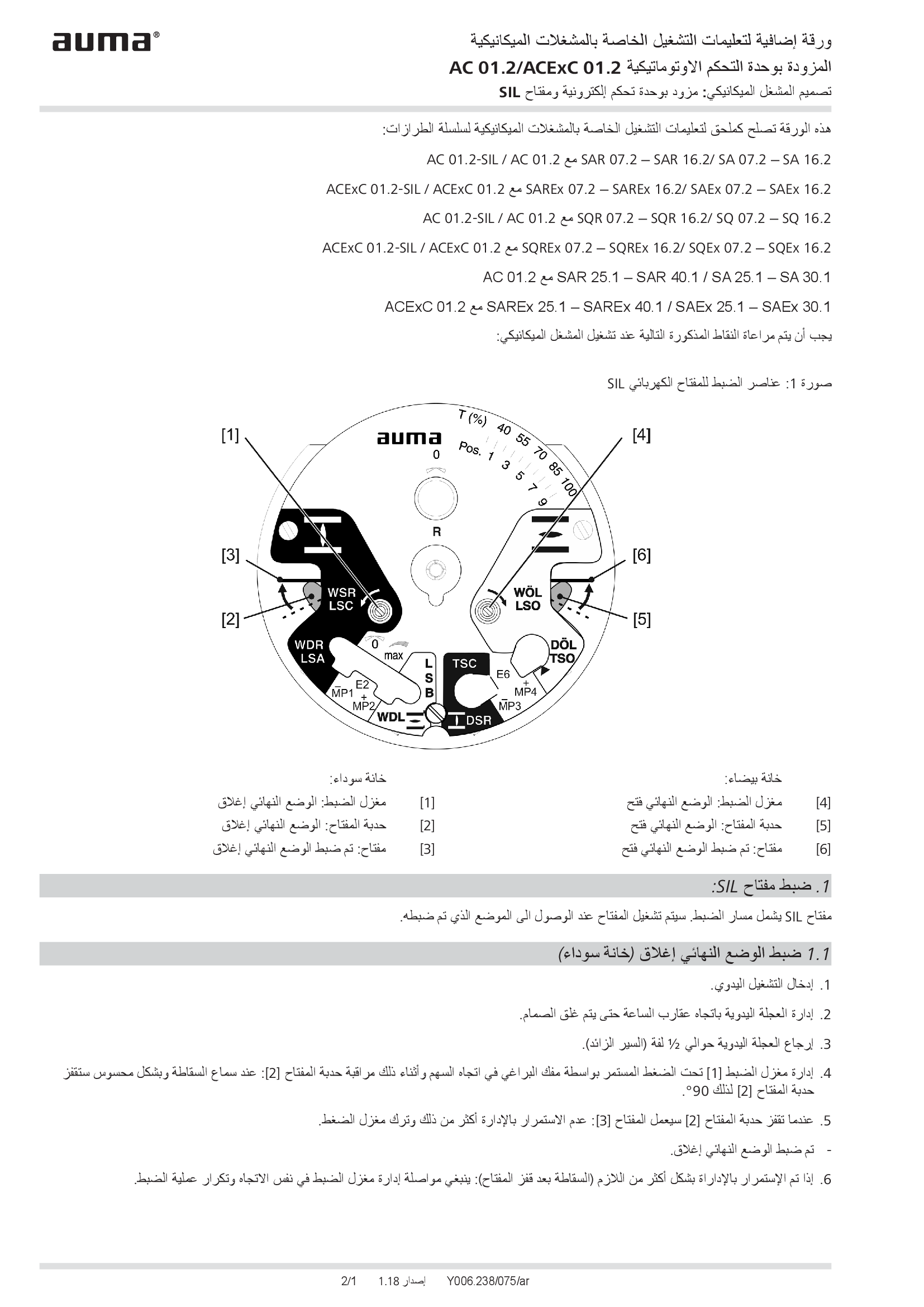
Supplement AUMATIC AC 01.2/ACExC 01.2, version actuators: with elektronic control unit (MWG) and SIL limit switching
Technical description
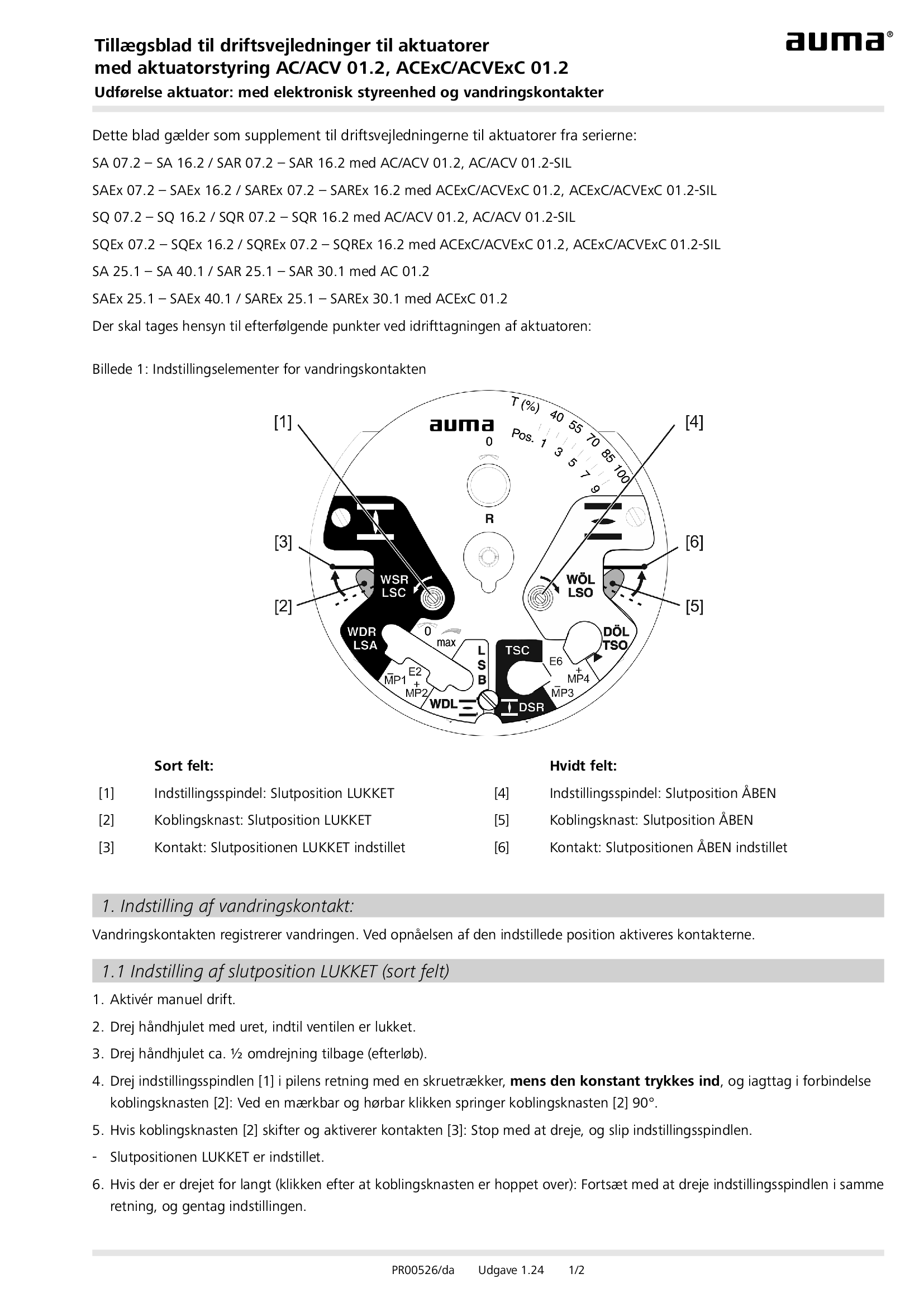
Supplement AUMATIC AC 01.2/ACExC 01.2, version actuators: with elektronic control unit (MWG) and limit switching
Technical description
Wiring diagram

A1: AUMATIC AC 01.2 position feedback signal 0/4 - 20 mA (potentiometer in actuator), basic version, reversing contactors OPEN, STOP, CLOSE, EMERGENCY (24 V DC), 6 programmable output contacts, AUMA power class A1 - A3
Wiring diagram

A1: AUMATIC ACExC 01.2 position feedback signal 0/4 - 20 mA (potentiometer in actuator),basic version, reversing contactors CLOSE, OPEN, STOP, EMERGENCY (24 V DC), 6 programmable output contacts, AUMA power class A1 - A3
Wiring diagram

A1N: AUMATIC AC 01.2 position/torque feedback signal 0/4 - 20 mA (MWG in actuator), reversing contactors OPEN, STOP, CLOSE, EMERGENCY (24 V DC), 6 programmable output contacts, AUMA power class A1 - A3
Wiring diagram

A1N: AUMATIC ACExC 01.2 position/torque feedback signal 0/4 - 20 mA (MWG in actuator), reversing contactors CLOSE, OPEN, STOP, EMERGENCY (24 V DC), 6 programmable output contacts, AUMA power class A1 - A3
Wiring diagram

A2: AUMATIC AC 01.2 positioner and postition feedback signal 0/4 - 20 mA (potentiometer in actuator), reversing contactors OPEN, STOP, CLOSE, EMERGENCY, MODE (24 V DC), 6 programmable output contacts, AUMA power class A1 - A3
Wiring diagram

A2: AUMATIC ACExC 01.2 positioner and position feedback signal 0/4 - 20 mA (potentiometer in actuator), reversing contactors MODE, CLOSE, OPEN, STOP, EMERGENCY (24 V DC), setpoint (0/4 - 20 mA), 6 programmable output contacts, AUMA power class A1 -
Wiring diagram

A2DP: AUMATIC AC 01.2 position feedback (potentiometer in actuator), basic version, reversing contactors, Profibus, AUMA power class A1 - A3
Wiring diagram

A2DP: AUMATIC ACExC 01.2 position feedback (potentiometer in actuator), basic version, reversing contactors, Profibus, AUMA power class A1 - A3
Wiring diagram

A2ENIP: AUMATIC AC 01.2 position feedback (potentiometer in actuator), basic version, reversing contactors, Ethernet/IP, AUMA power class A3 - A3
Wiring diagram

A2ENIP: AUMATIC ACExC 01.2 position feedback (potentiometer in actuator), basic version, reversing contactors, EtherNet/IP, AUMA power class A1 - A3
Wiring diagram

A2FF: AUMATIC AC 01.2 position feedback (potentiometer in actuator), basic version, Reversing contactors, Foundation Fieldbus FF, AUMA power classes A1 – A3
Wiring diagram

A2FF: AUMATIC ACExC 01.2 position feedback (potentiometer in actuator), basic version, reversing contactors, Foundation Fieldbus FF, AUMA power class A1 - A3
Wiring diagram

A2HRT: AUMATIC AC 01.2 position feedback (potentiometer in actuator), basic version, Reversing contactors, HART actuatorAUMA power classes A1 – A3
Wiring diagram

A2HRT: AUMATIC ACExC 01.2 position feedback (potentiometer in actuator), reversing contactors, HART actuator, AUMA power class A1 - A3
Wiring diagram

A2HRTCO: AUMATIC AC 01.2 position feedback (potentiometer in actuator), basic version, Reversing contactors, HART Current Output, AUMA power classes A1 – A3
Wiring diagram

A2HRTCO: AUMATIC ACExC 01.2 position feedback (potentiometer in actuator), basic version, reversing contactors, HART current output, AUMA power class A1 - A3
Wiring diagram

A2MB: AUMATIC AC 01.2 position feedback (potentiometer in actuator), basic version, reversing contactors, Modbus RTU, AUMA power class A1 - A3
Wiring diagram

A2MB: AUMATIC ACExC 01.2 position feedback (potentiometer in acuator), basic version, reversing contactors, Modbus, AUMA power class A1 - A3
Wiring diagram

A2MBTCP: AUMATIC AC 01.2 position feedback (potentiometer in actuator), basic version, Reversing contactors, Modbus TCP/IP, AUMA power classes A1 – A3
Wiring diagram

A2MBTCP: AUMATIC AC 01.2 position/torque feedback (MWG in actuator), Reversing contactors, Modbus TCP/IP, AUMA power classes A1 – A3
Wiring diagram

A2MBTCP: AUMATIC ACExC 01.2 position feedback (potentiometer in actuator), basic version, reversing contactors, Modbus TCP/IP, AUMA power class A1 - A3
Wiring diagram

A2N: AUMATIC AC 01.2 positioner and position/torque feedback signal 0/4 - 20 mA (MWG in actuator), , reversing contactors OPEN, STOP, CLOSE, EMERGENCY, MODE (24 V DC), 6 programmable output contacts, AUMA power class A1 - A3
Wiring diagram

A2N: AUMATIC ACExC 01.2 positioner and position/torque feedback signal 0/4 - 20 mA (MWG in actuator), reversing contactors MODE, CLOSE, OPEN, STOP, EMERGENCY (24 V DC), 6 programmable output contacts, AUMA power class A1 - A3
Wiring diagram

A2NDP: AUMATIC AC 01.2 position/torque feedback (MWG in actuator), reversing contactors, Profibus, AUMA power class A1 - A3
Wiring diagram

A2NDP: AUMATIC ACExC 01.2 position/torque feedback (MWG in actuator), reversing contactors, Profibus, AUMA power class A1 - A3
Wiring diagram

A2NENIP: AUMATIC AC 01.2, position/torque feedback (MWG in actuator, reversing contactors, Ethernet/IP, AUMA power class A1 - A 3
Wiring diagram

A2NENIP: AUMATIC ACExC 01.2 position/torque feedback (MWG in actuator), reversing contactors, EtherNet/IP, AUMA power class A1 - A3
Wiring diagram

A2NFF: AUMATIC AC 01.2 position/torque feedback (MWG in actuator), Reversing contactors, Foundation Fieldbus FF, AUMA power classes A1 – A3
Wiring diagram

A2NFF: AUMATIC ACExC 01.2 Stellungs-/Drehmomentrückmeldung (MWG im Stellanrieb), Schütze, Foundation Fieldbus FF, AUMA Leisungsklasse A1 - A3
Wiring diagram

A2NFF: AUMATIC ACExC 01.2 position/torque feedback (MWG in actuator), reversing contactors, Foundation Fieldbus FF, AUMA power class A1 - A3
Wiring diagram

A2NHRT: AUMATIC AC 01.2 position/torque feedback (MWG in actuator), Reversing contactors, HART actuator, AUMA power classes A1 – A3
Wiring diagram

A2NHRT: AUMATIC ACExC 01.2 position/torque feedback (MWG in actuator), reversing contactors, HART actuator, AUMA power class A1 - A3
Wiring diagram

A2NHRTCO: AUMATIC AC 01.2 position/torque feedback (MWG in actuator), Reversing contactors, HART Current Output, AUMA power classes A1 – A3
Wiring diagram

A2NHRTCO:AUMATIC ACExC 01.2 position/torque feedback (MWG in actuator), reversing contactors, HART current output, AUMA power class A1 - A3
Wiring diagram

A2NMB: AUMATIC AC 01.2 position/torque feedback (MWG in actuator), reversing contactors, Modbus RTU, AUMA power class A1 - A3
Wiring diagram

A2NMB: AUMATIC ACExC 01.2 position/torque feedback (MWG in actuator), reversing contactors, Modbus, AUMA power class A1 - A3
Wiring diagram

A2NMBTCP: AUMATIC ACExC 01.2 position/torque feedback (MWG in actuator), reversing contactors, Modbus TCP/IP, AUMA power class A1 - A3
Wiring diagram

A3: AUMATIC AC 01.2 positioner and position feedback signal 0/4 - 20 mA (potentiometer in actuator), thyristors OPEN, STOP, CLOSE, EMERGENCY, MODE (24 V DC), 6 programmable output contacts, AUMA power class B1/B2
Wiring diagram

A3: AUMATIC AC 01.2 positioner and position feedback signal 0/4 - 20 mA (potentiometer in actuator), thyristors OPEN, STOP, CLOSE, EMERGENCY, MODE (24 V DC), 6 programmable output contacts, AUMA power class B3
Wiring diagram

A3: AUMATIC ACExC 01.2 positioner and position feedback signal 0/4 - 20 mA (potentiometer in actuator), thyristors MODE, CLOSE, OPEN, STOP, EMERGENCY (24 V DC), setpoint (0/4 - 20 mA) 6 programmable output contacts, AUMA power class B1/B2
Wiring diagram

A3: AUMATIC ACExC 01.2 positioner and position feedback signal 0/4 - 20 mA (potentiometer in actuator), thyristors MODE, CLOSE, OPEN, STOP, EMERGENCY (24 V DC), setpoint (0/4 - 20 mA) 6 programmable output contacts, AUMA power class B3
Wiring diagram