Zoekresultaten voor
"AUMA Service – Premium Service across the entire lifecycle"
Product certificate

KOSHA Certificate for TIGRON TR-M30X, TR-MR30X and TR-CWX in the type of protection Ex db eb
Product certificate

KOSHA Certificate for TIGRON TR-M30X, TR-MR30X and TR-CWX in the type of protection Ex tD
Product certificate

KOSHA Certificate for TIGRON TR-M500X, TR-MR500X and TR-CWX in the type of protection Ex db
Product certificate

KOSHA Certificate for TIGRON TR-M500X, TR-MR500X and TR-CWX in the type of protection Ex db eb
Product certificate

KOSHA Certificate for TIGRON TR-M500X, TR-MR500X and TR-CWX in the type of protection Ex tD
Product certificate

KOSHA Certificate for TIGRON TR-M60X, TR-MR60X and TR-CWX in the type of protection Ex db
Product certificate

KOSHA Certificate for TIGRON TR-M60X, TR-MR60X and TR-CWX in the type of protection Ex db eb
Product certificate

KOSHA Certificate for TIGRON TR-M60X, TR-MR60X and TR-CWX in the type of protection Ex tD
Product certificate
Route map
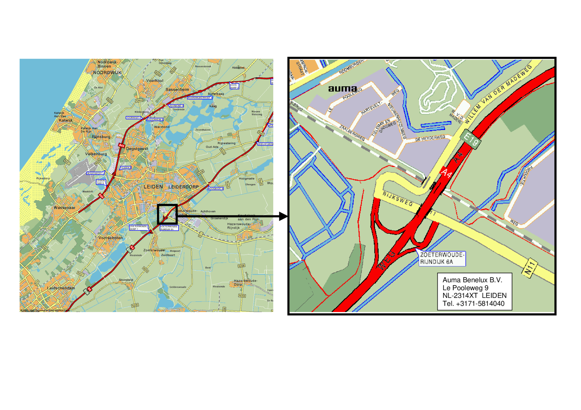
Route to AUMA Benelux
Route map
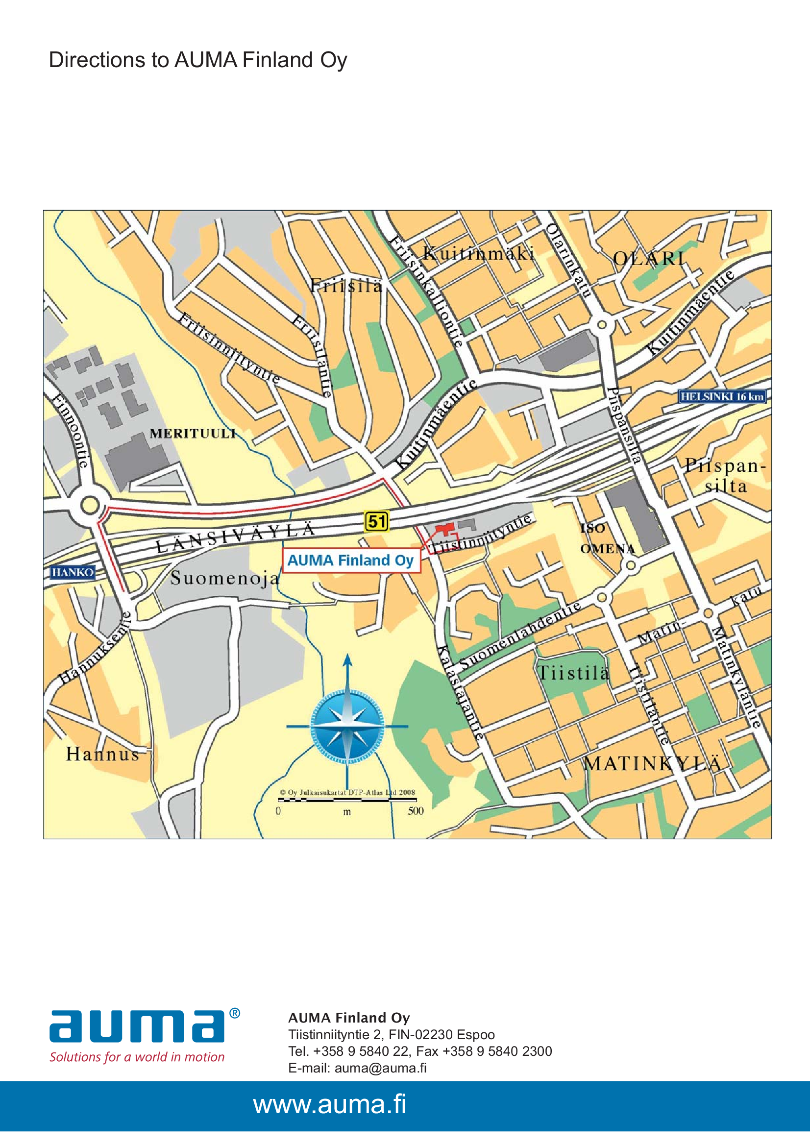
Route to AUMA Finland
Route map
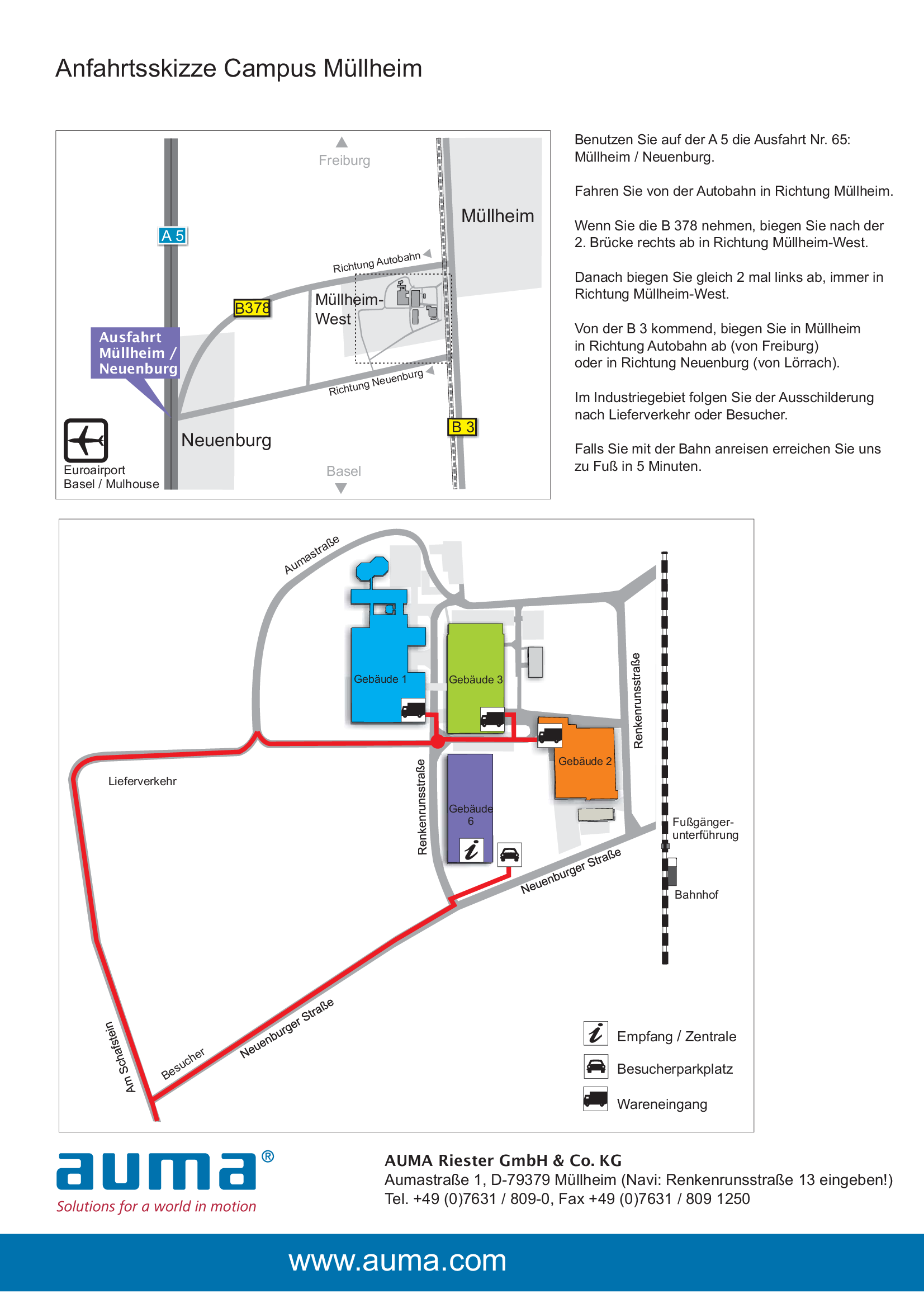
The route to AUMA (Campus Müllheim)
Route map
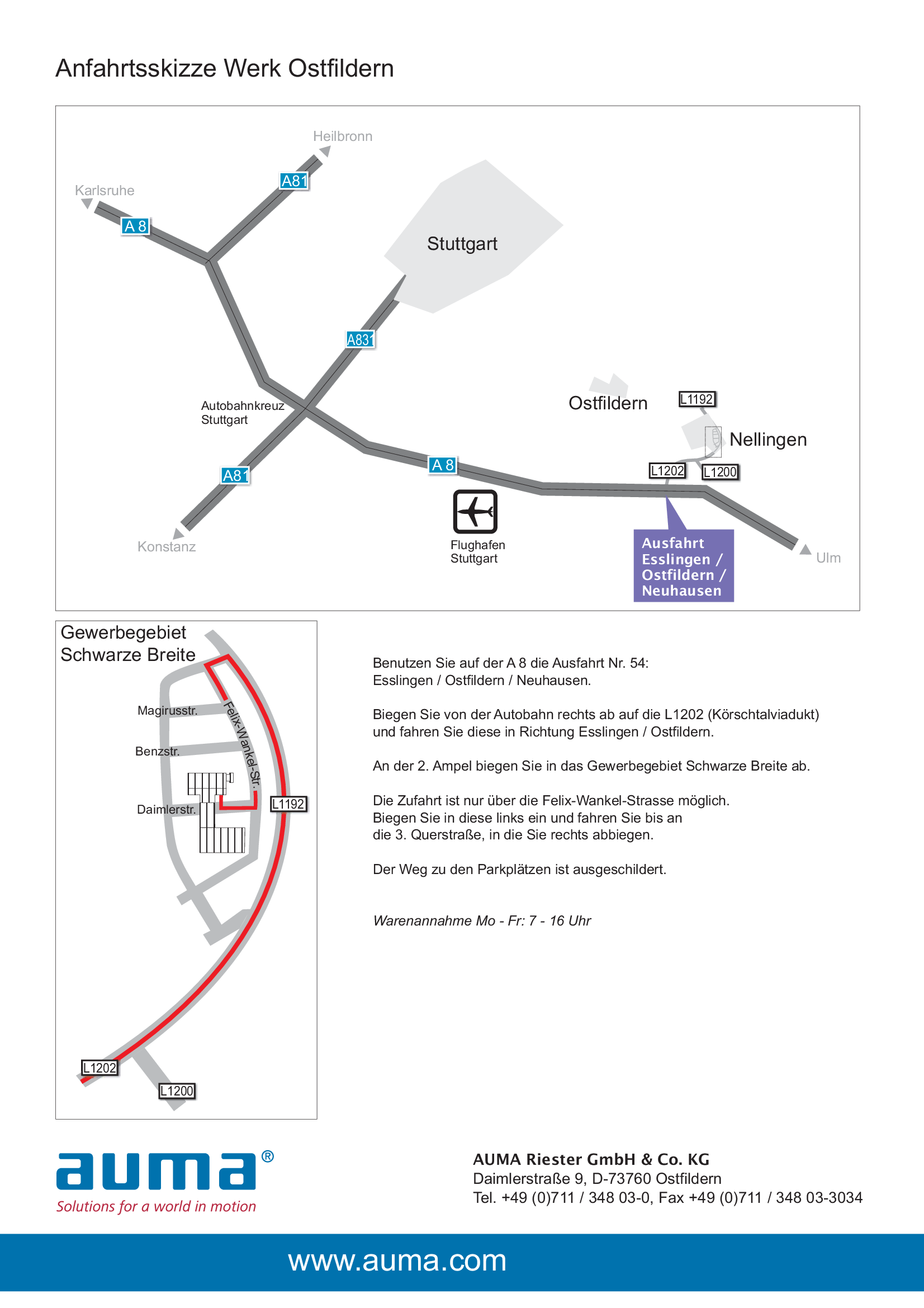
The route to AUMA (Plant Ostfildern)
Route map
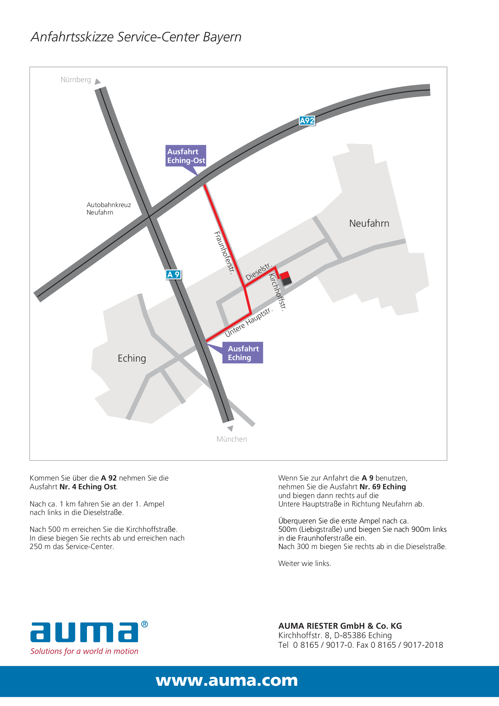
The route to AUMA (Service Center Bayern)
Route map
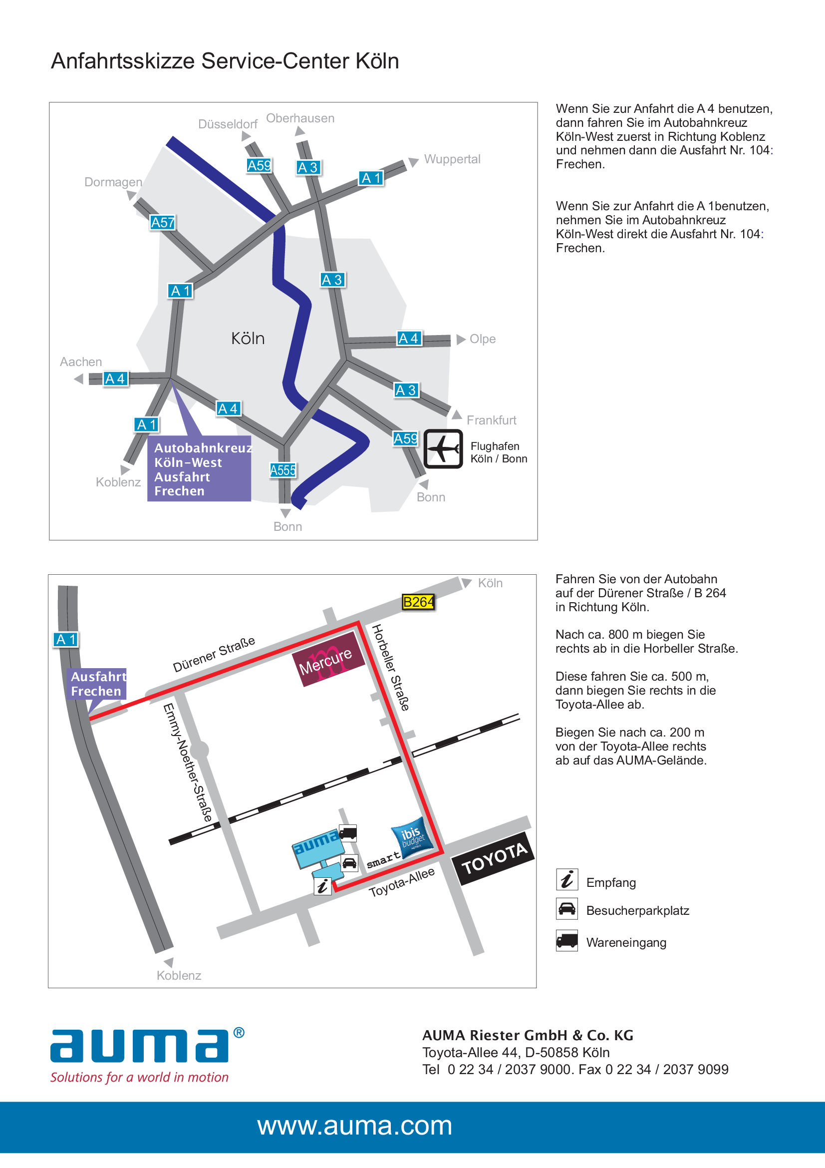
The route to AUMA (Service Center Köln)
Route map
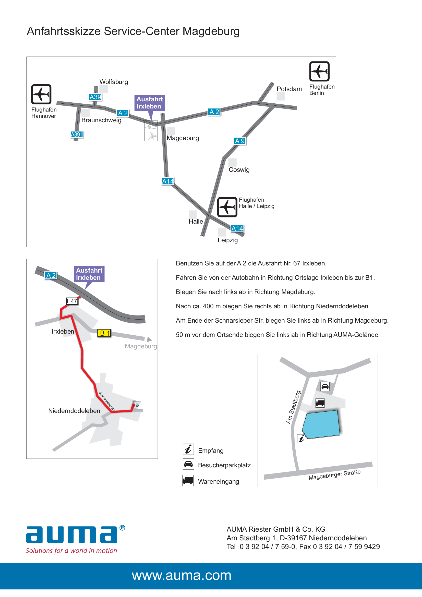
The route to AUMA (Service Center Magdeburg)
Route map
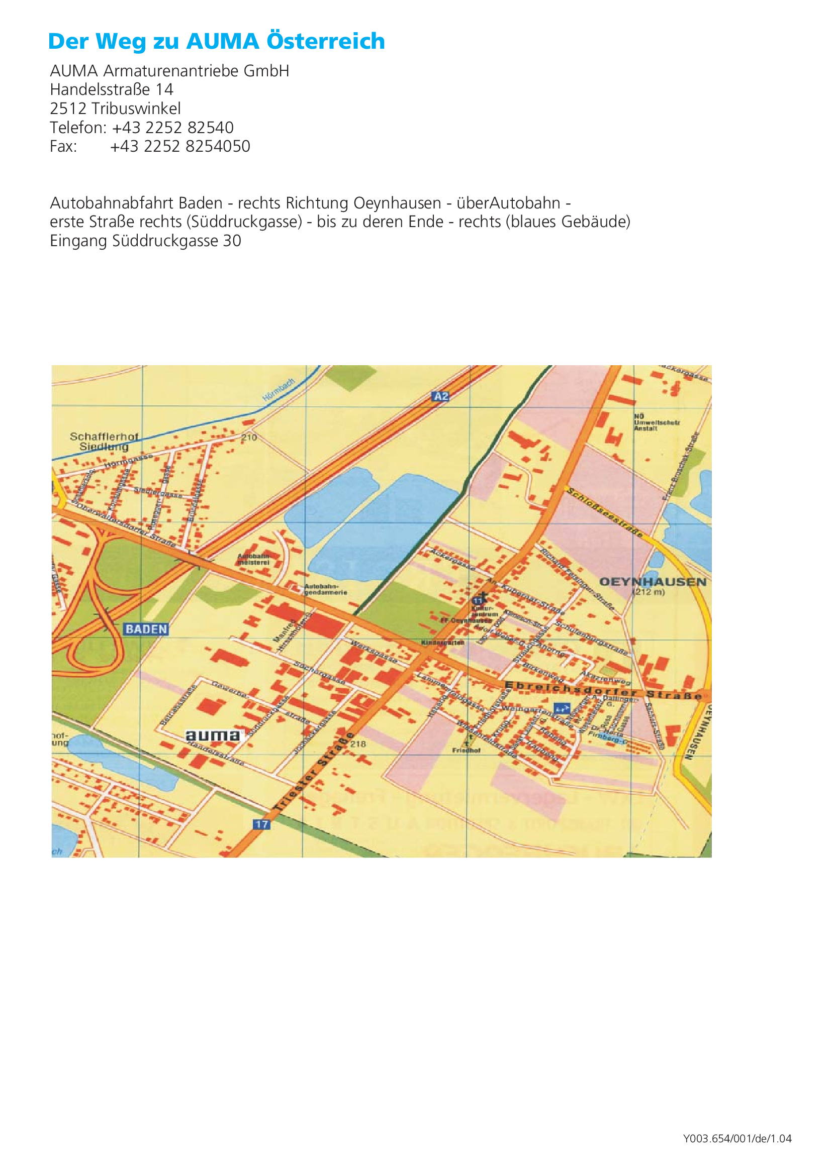
The route to AUMA Austria
Route map
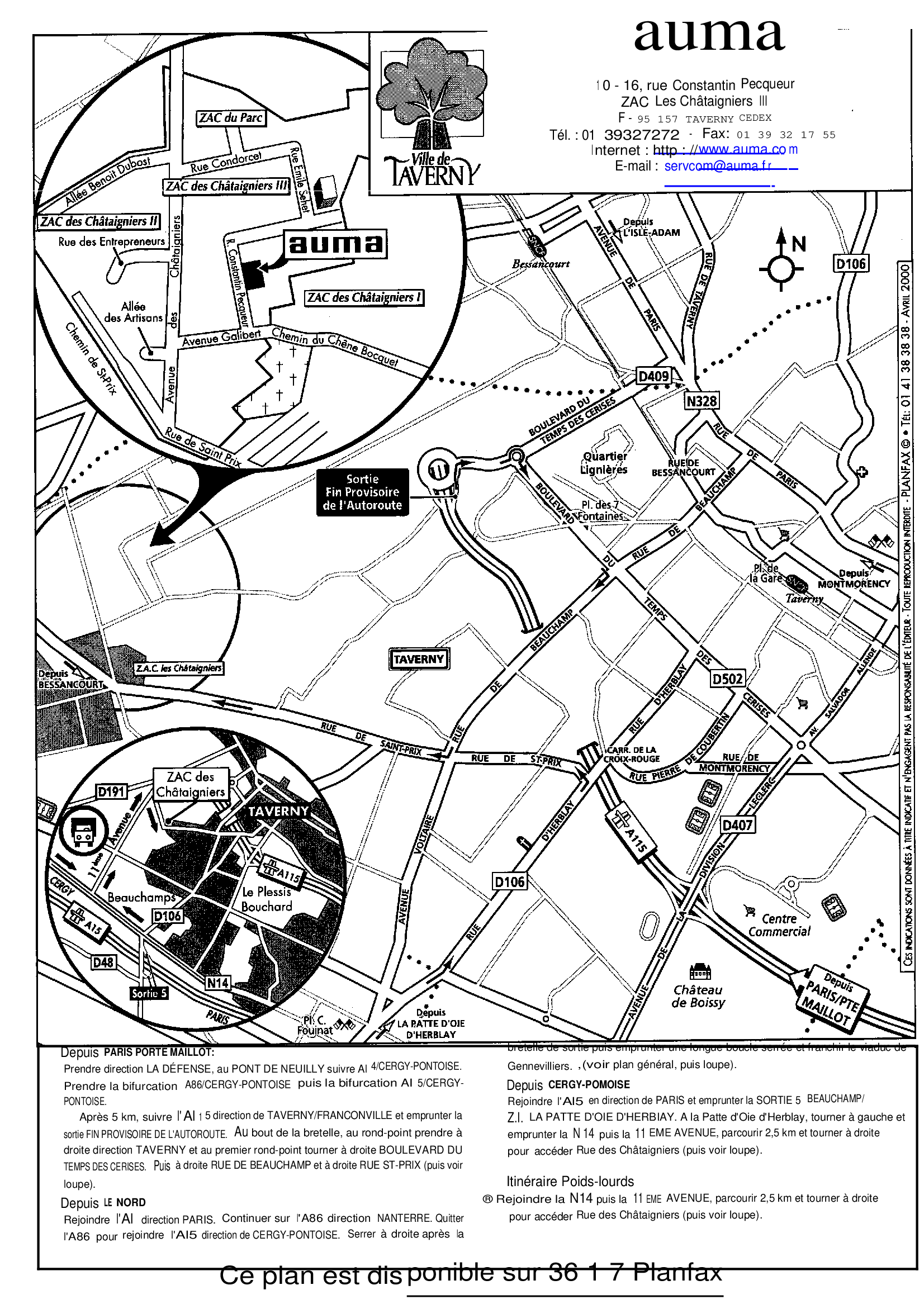
The route to AUMA France
Route map
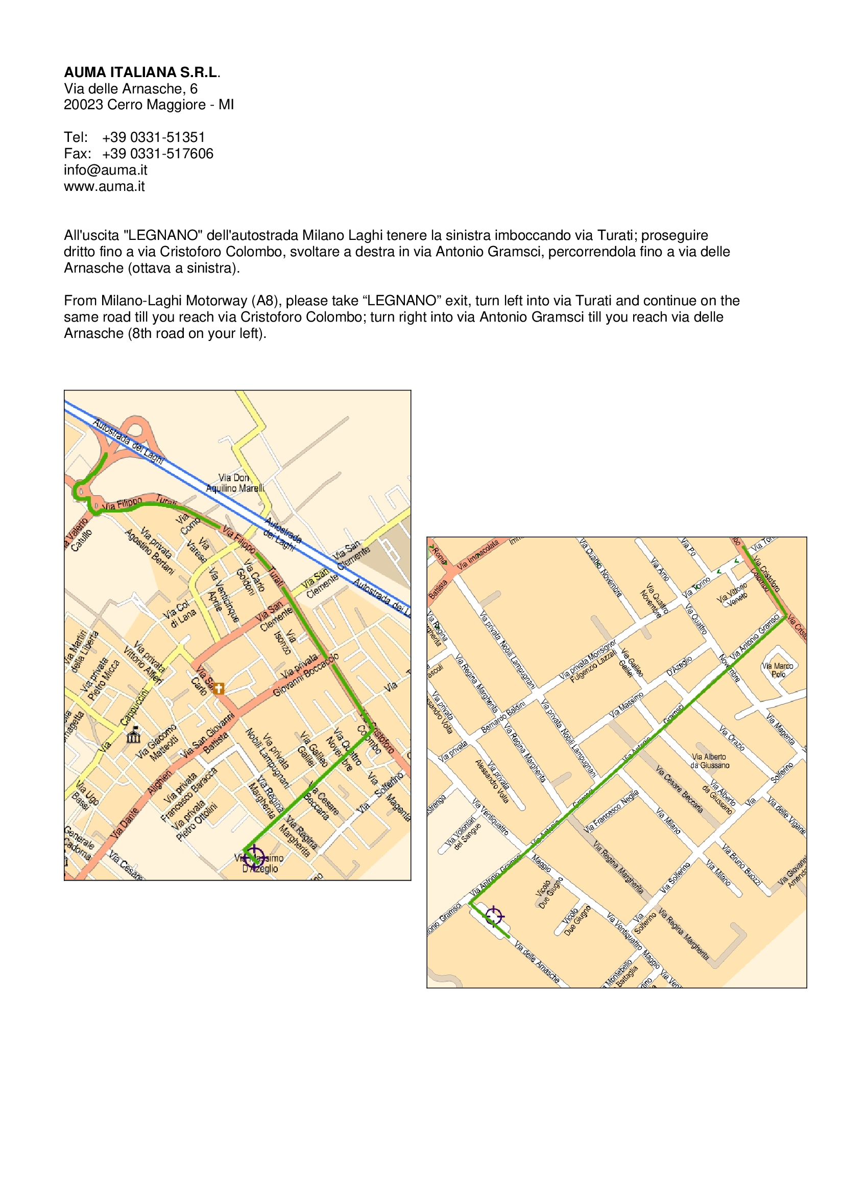
The route to AUMA Italy
Route map
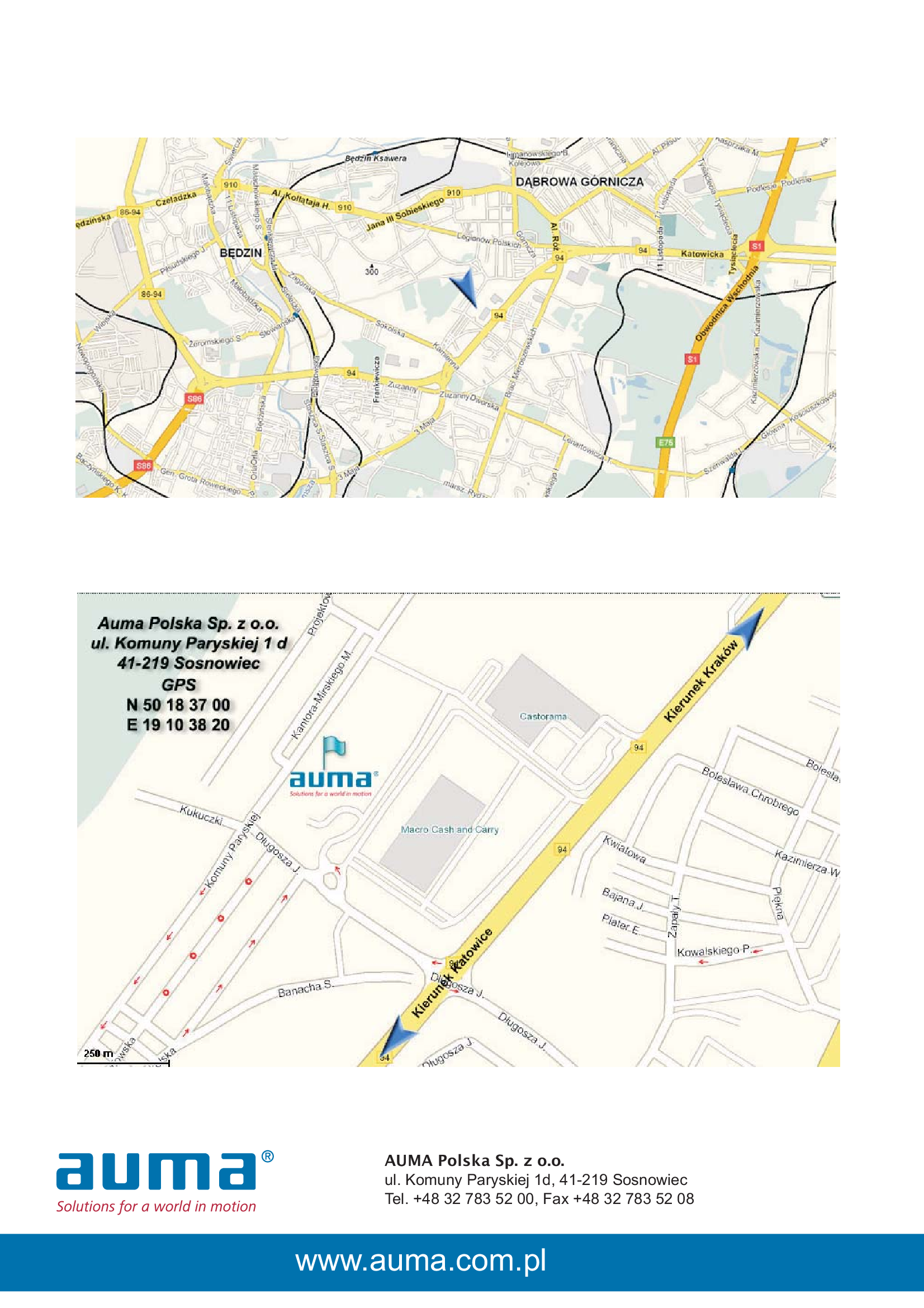
The route to AUMA Poland
Route map
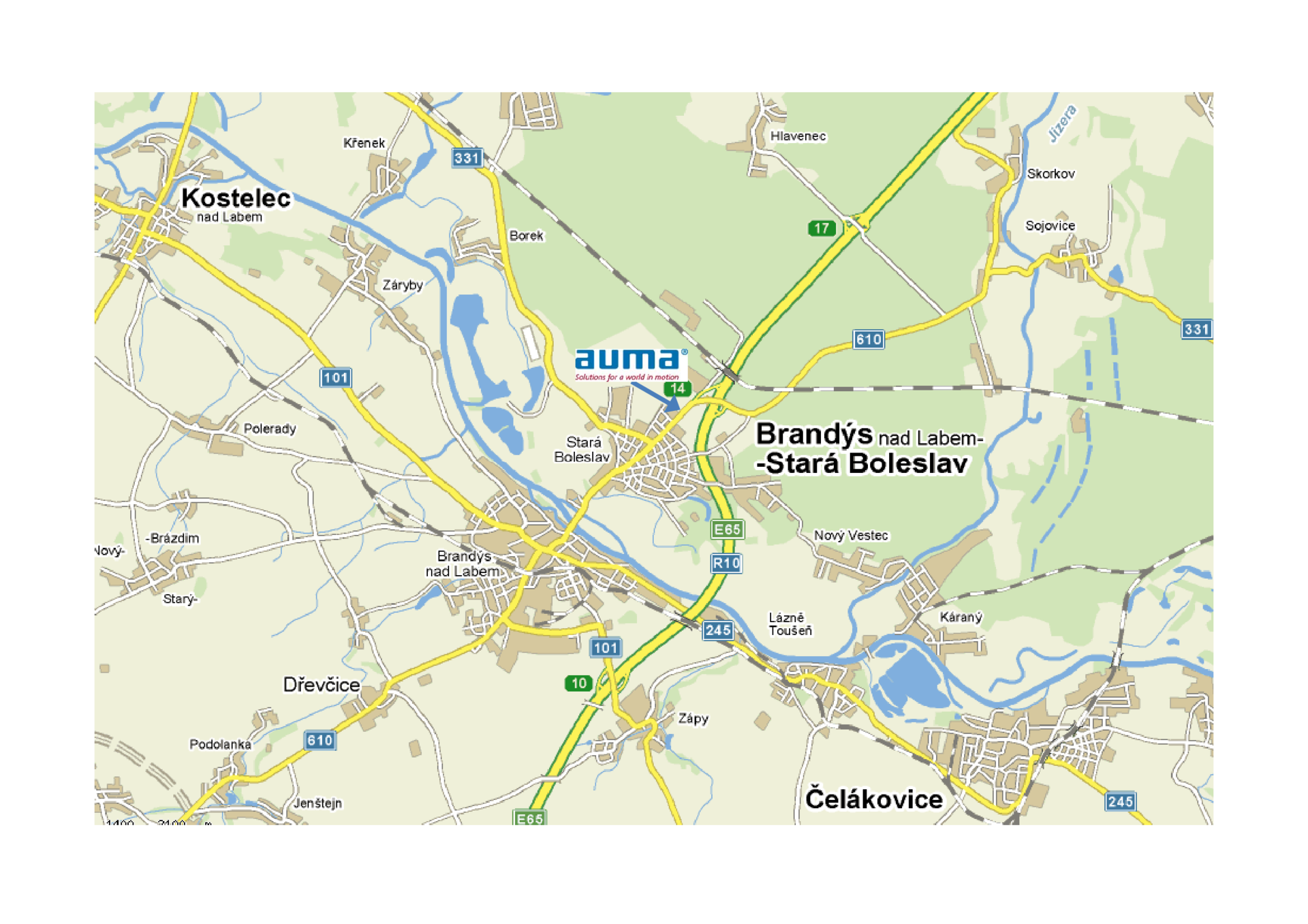
The route to AUMA Servopohony
Route map
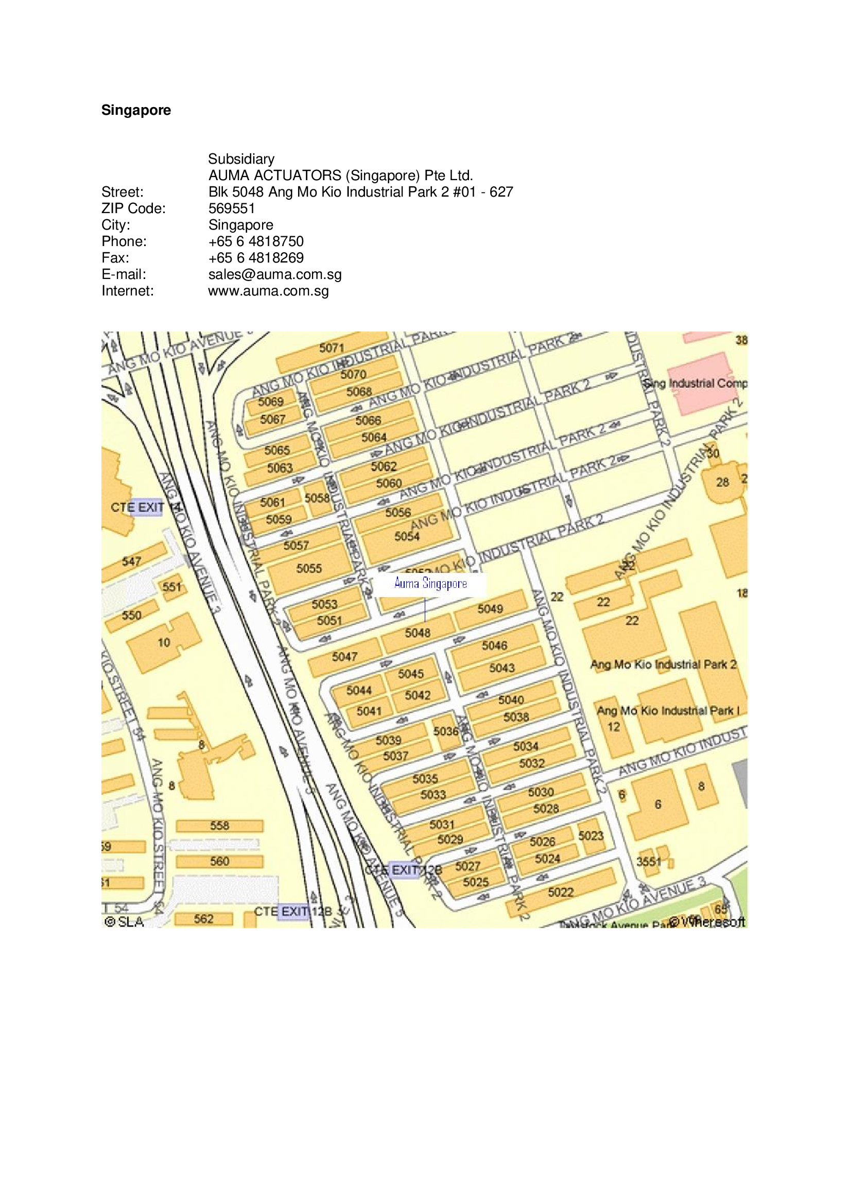
The route to AUMA Singapore
Route map
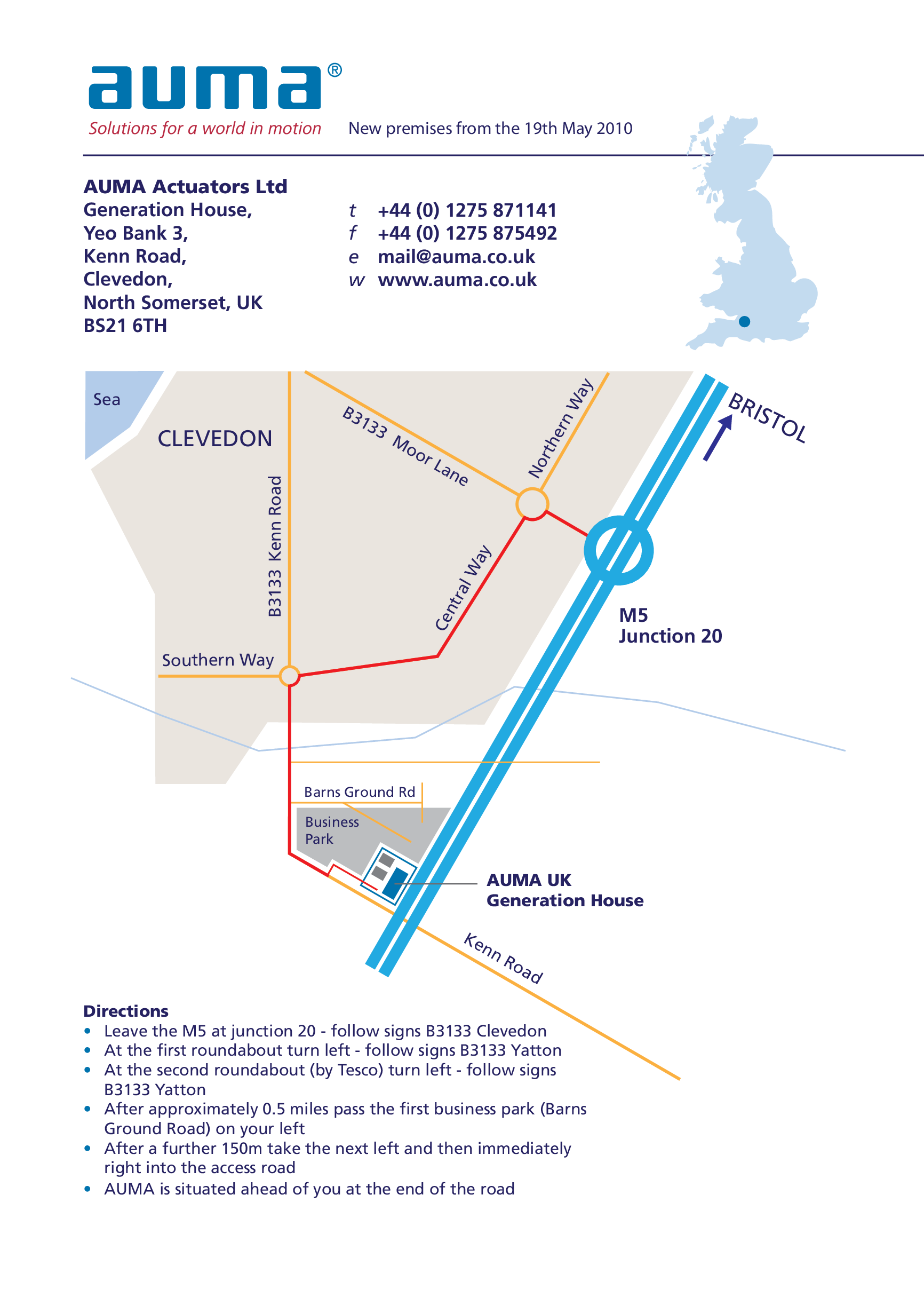
The route to AUMA UK
Route map
The route to OOO “Stels”
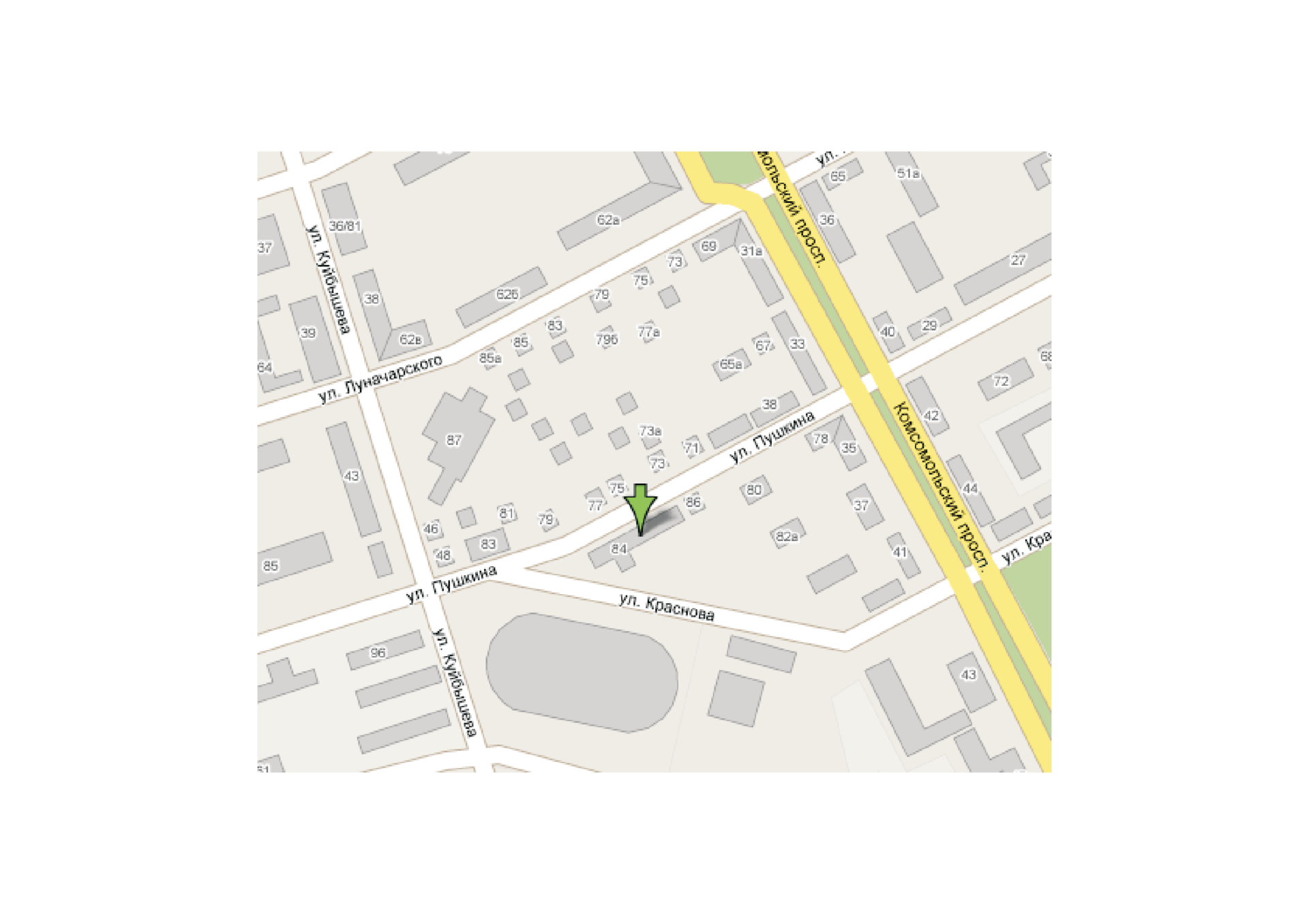
Route map
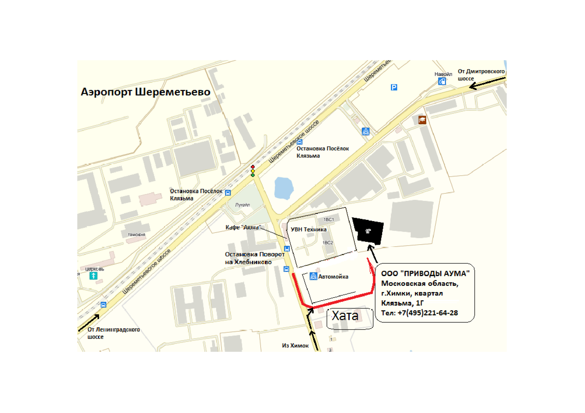
The route to Priwody AUMA / Khimki/Moscow
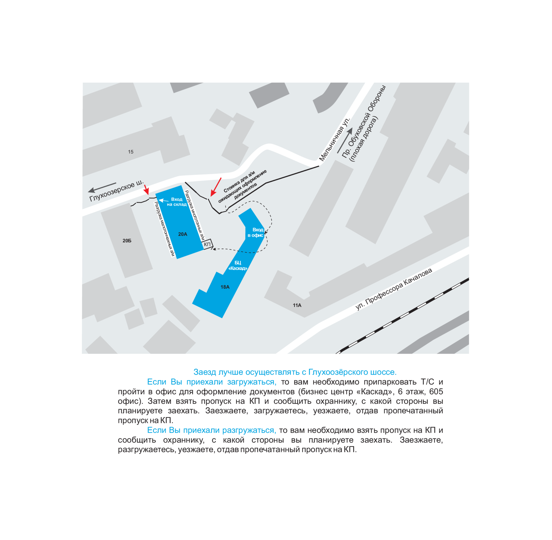
Route map
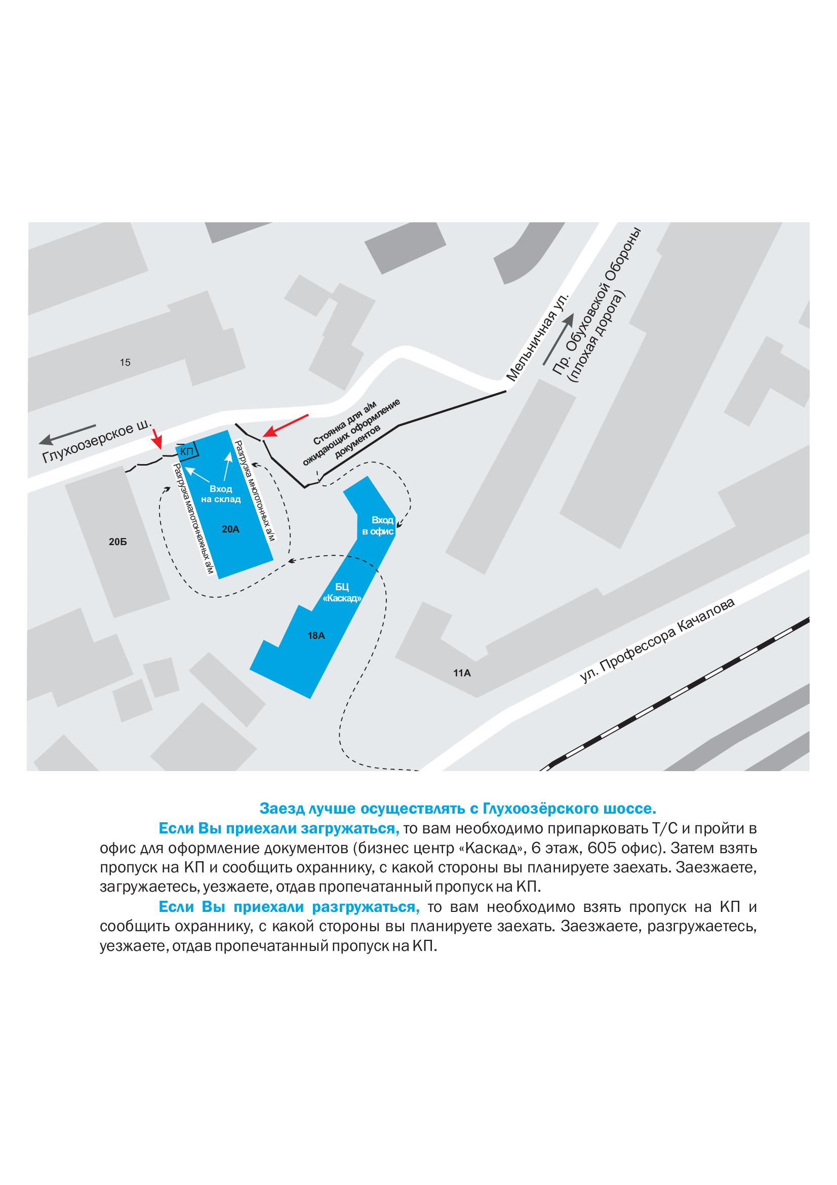
The route to Priwody AUMA / St. Petersburg
Route map
The route to Priwody AUMA / Tushino
Route map
Spare parts list
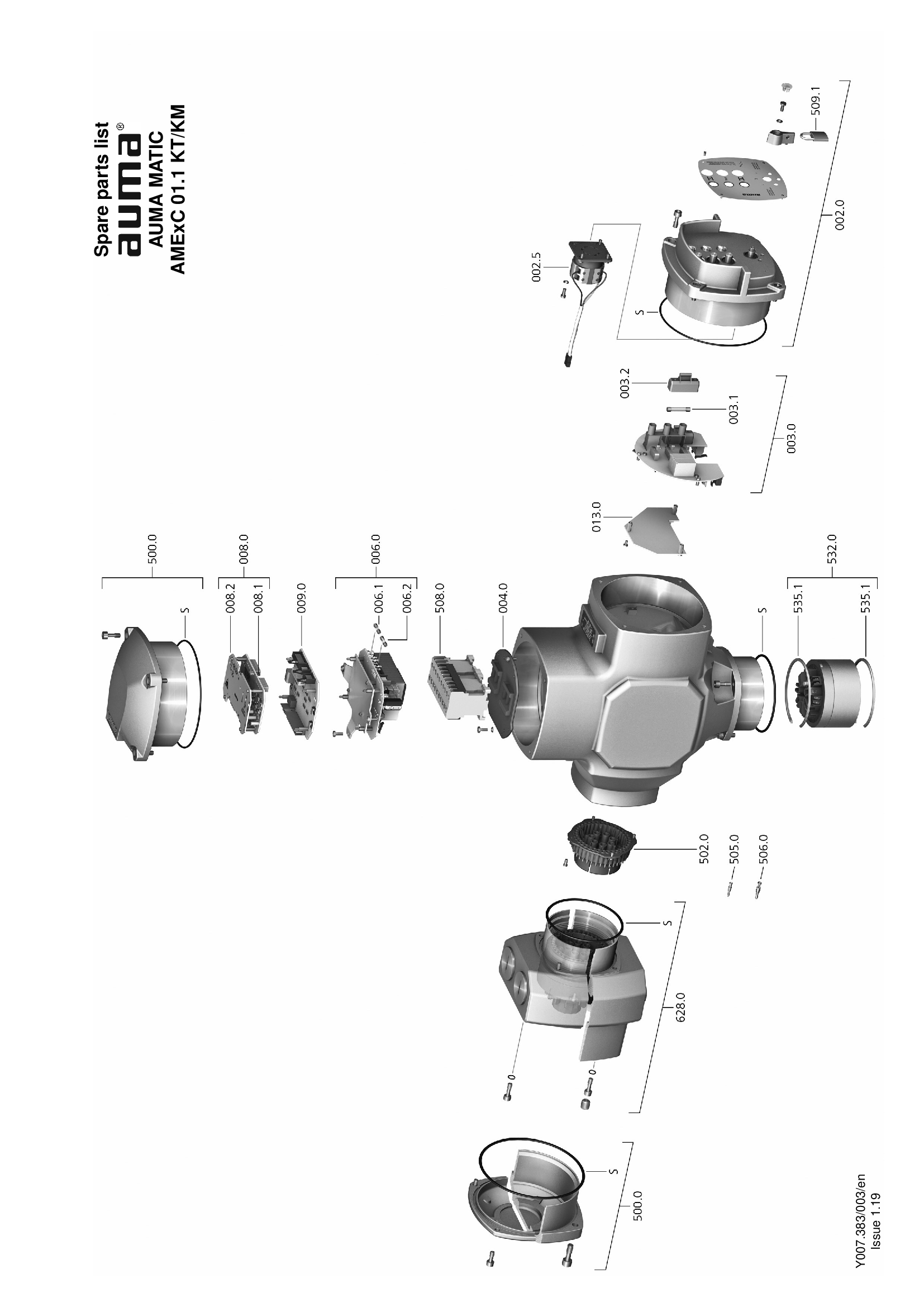
Actuator controls AUMA MATIC 01.1 KT/KM
Spare parts list

Actuator controls AUMA MATIC AM 01.1 - 02.1, seals
Spare parts list
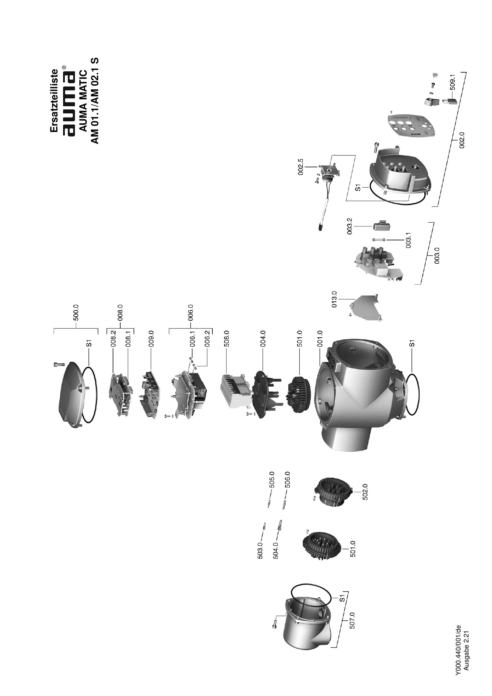
Actuator controls AUMA MATIC AM 01.1 – 02.1
Spare parts list
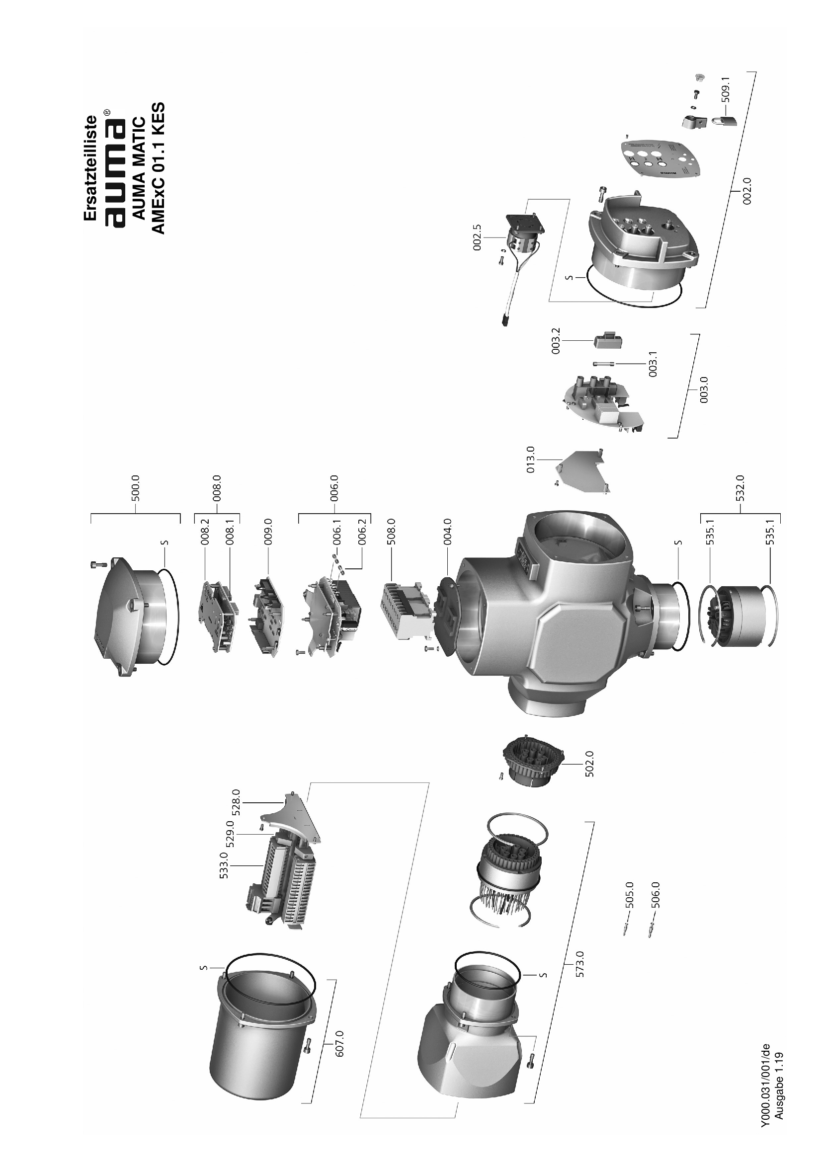
Actuator controls AUMA MATIC AMExC 01.1 KES
Spare parts list

Actuator controls AUMA MATIC AMExC 01.1 KES, seals
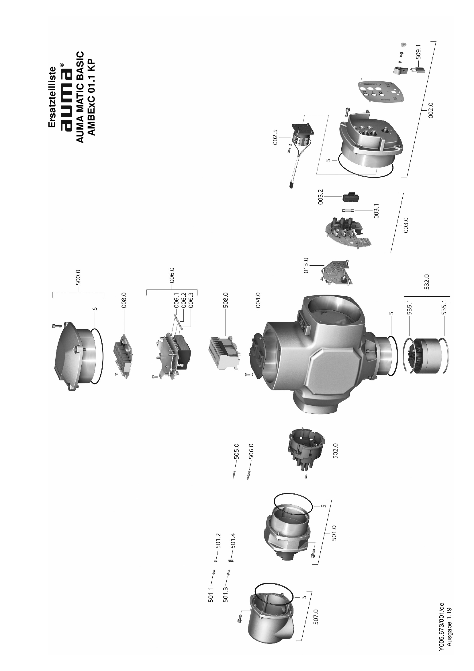
Spare parts list

Actuator controls AUMA MATIC AMExC 01.1 KP
Spare parts list
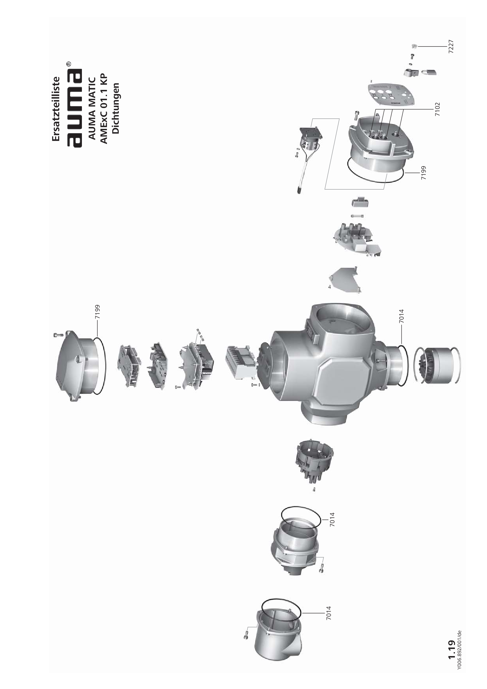
Actuator controls AUMA MATIC AMExC 01.1 KP, seals
Spare parts list

Actuator controls AUMA MATIC AMExC 01.1 KT/KM
Spare parts list
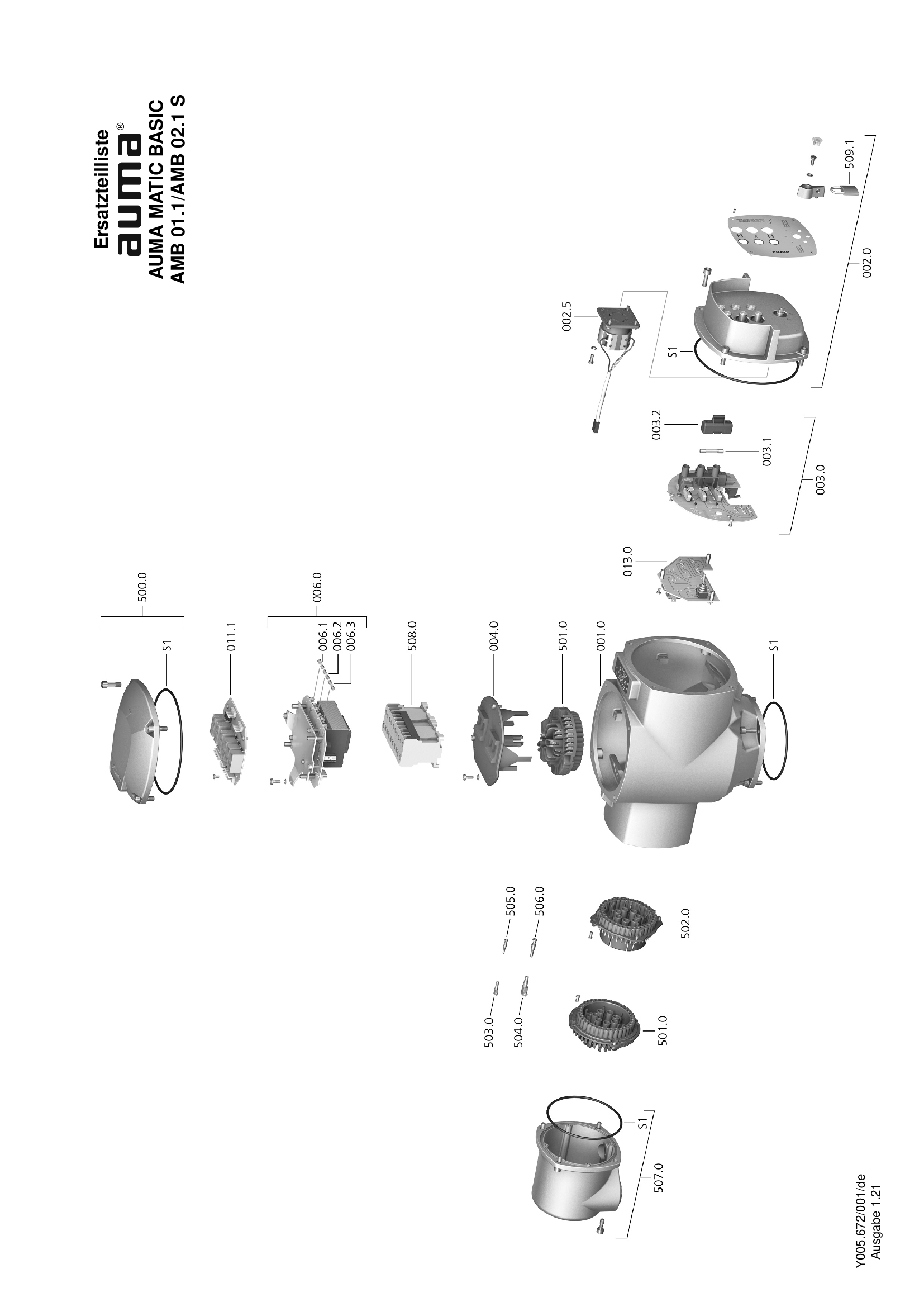
Actuator controls AUMA MATIC BASIC AMB 01.1 - 02.1
Spare parts list

Actuator controls AUMA MATIC BASIC AMB 01.1 - 02.1, seals
Spare parts list

Actuator controls AUMA MATIC BASIC AMBExC 01.1 KES
Spare parts list
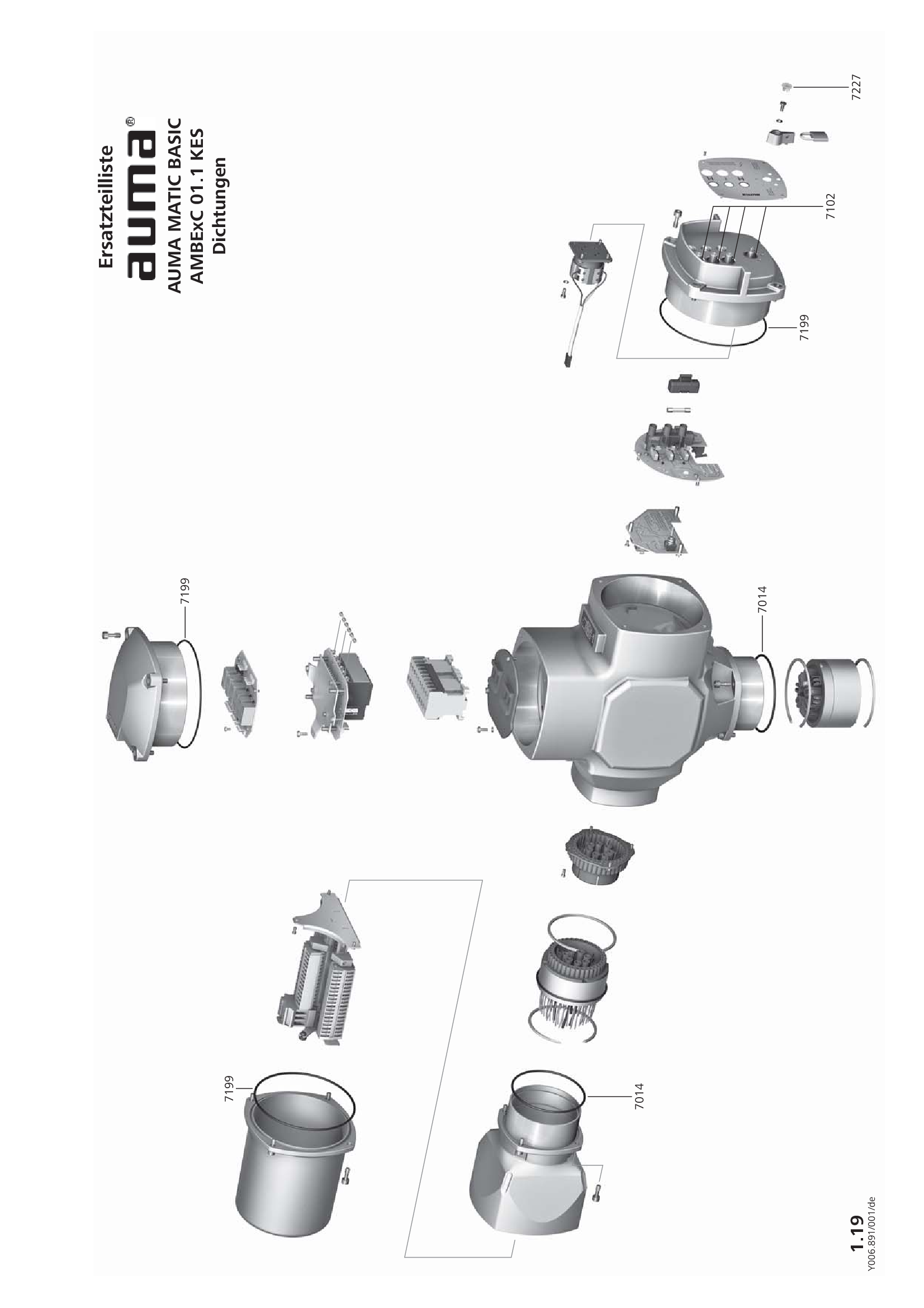
Actuator controls AUMA MATIC BASIC AMBExC 01.1 KES, seals
Spare parts list
Actuator controls AUMA MATIC BASIC AMBExC 01.1 KP
Spare parts list

Actuator controls AUMA MATIC BASIC AMBExC 01.1 KP, seals
Spare parts list

Actuator controls AUMA MATIC BASIC AMBExC 01.1 KT/KM
Spare parts list
Specification
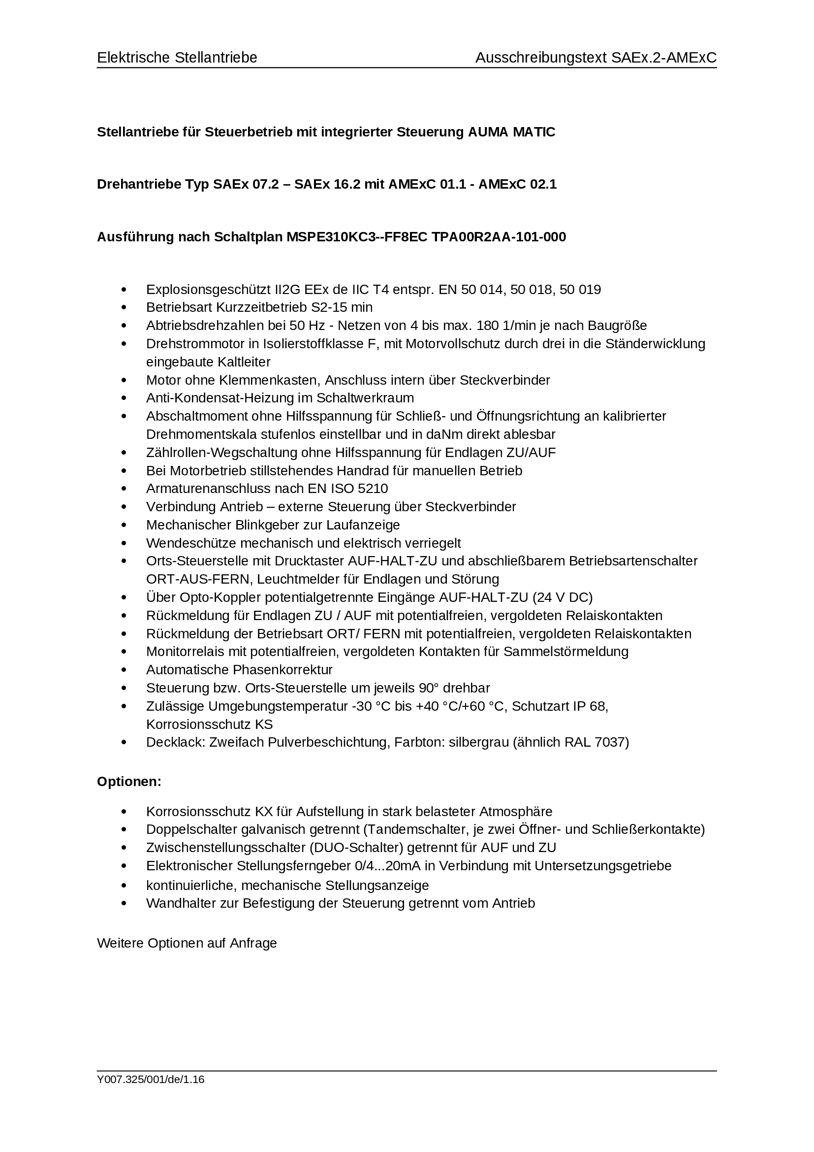
Explosion-proof multi-turn actuators SAEx 07.2 - 16.2 Explosion-proof actuator controls AUMA MATIC AMExC 01.1
Specification
Downloaden
application/vnd.openxmlformats-officedocument.wordprocessingml.document
43.7 KB
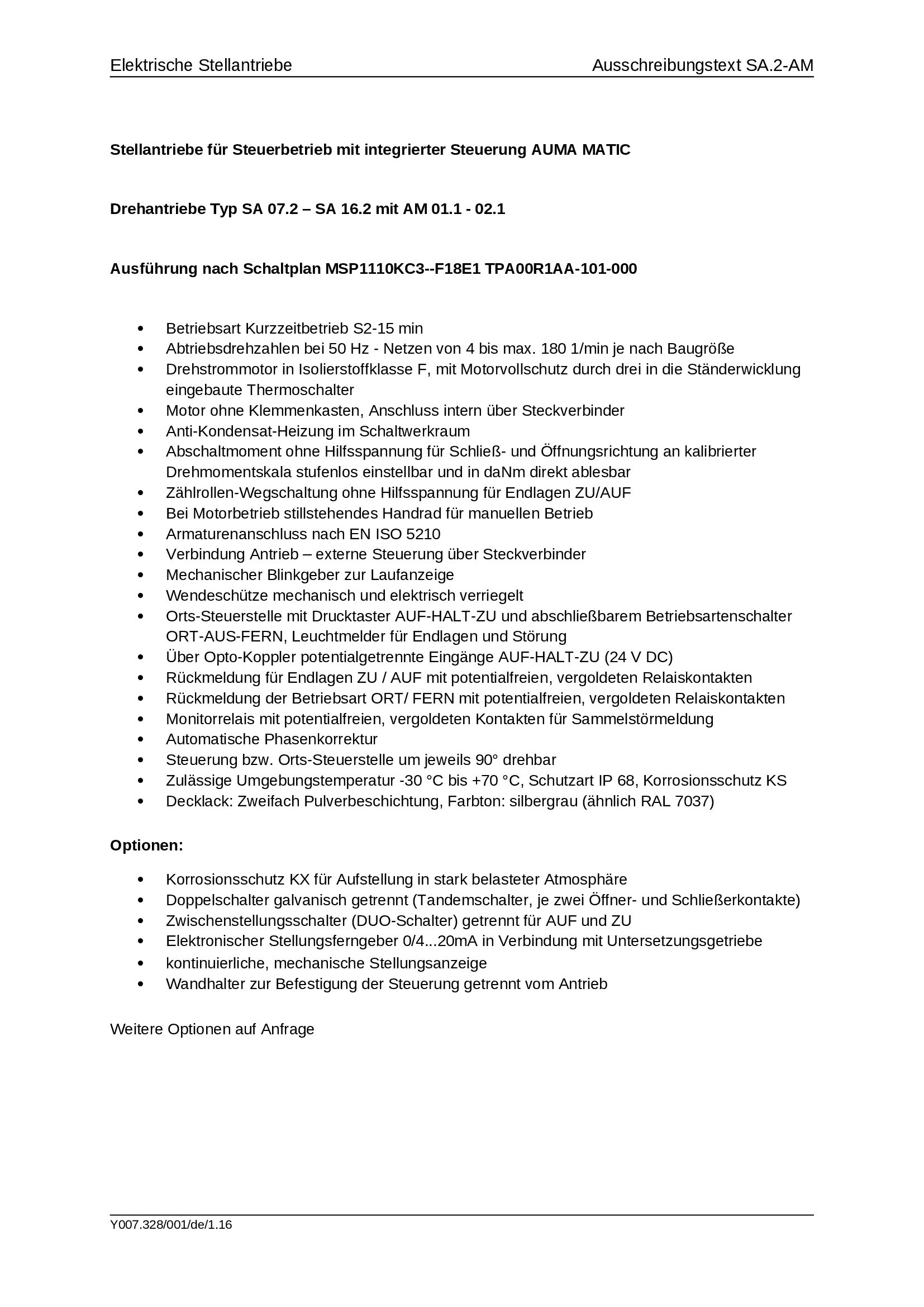
Multi-turn actuators SA 07.2 - 16.2 actuator controls AUMA MATIC AM 01.1
Specification
Downloaden
application/vnd.openxmlformats-officedocument.wordprocessingml.document
43.7 KB
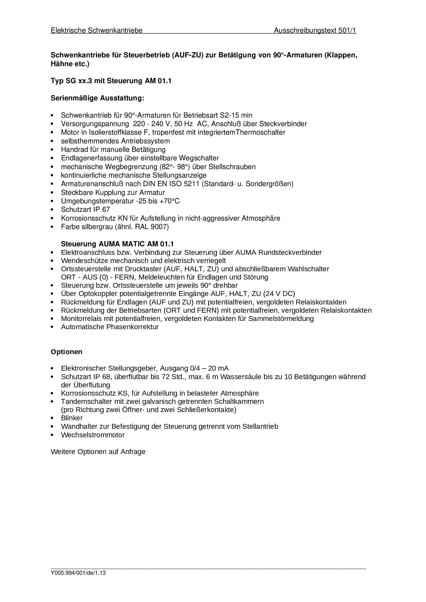
Part-turn actuators SG 03.3 - 05.3, Actuator controls AUMA MATIC AM 01.1
Specification
Technical Data Catalogue

Technical documentation 2024 - Electric actuators for valve automation in the oil & gas industry
Technical Data Catalogue

Technical documentation 2024 - Electric multi-turn actuators for valve automation in the oil & gas industry with high torque requirements
Technical Data Catalogue
Technical data
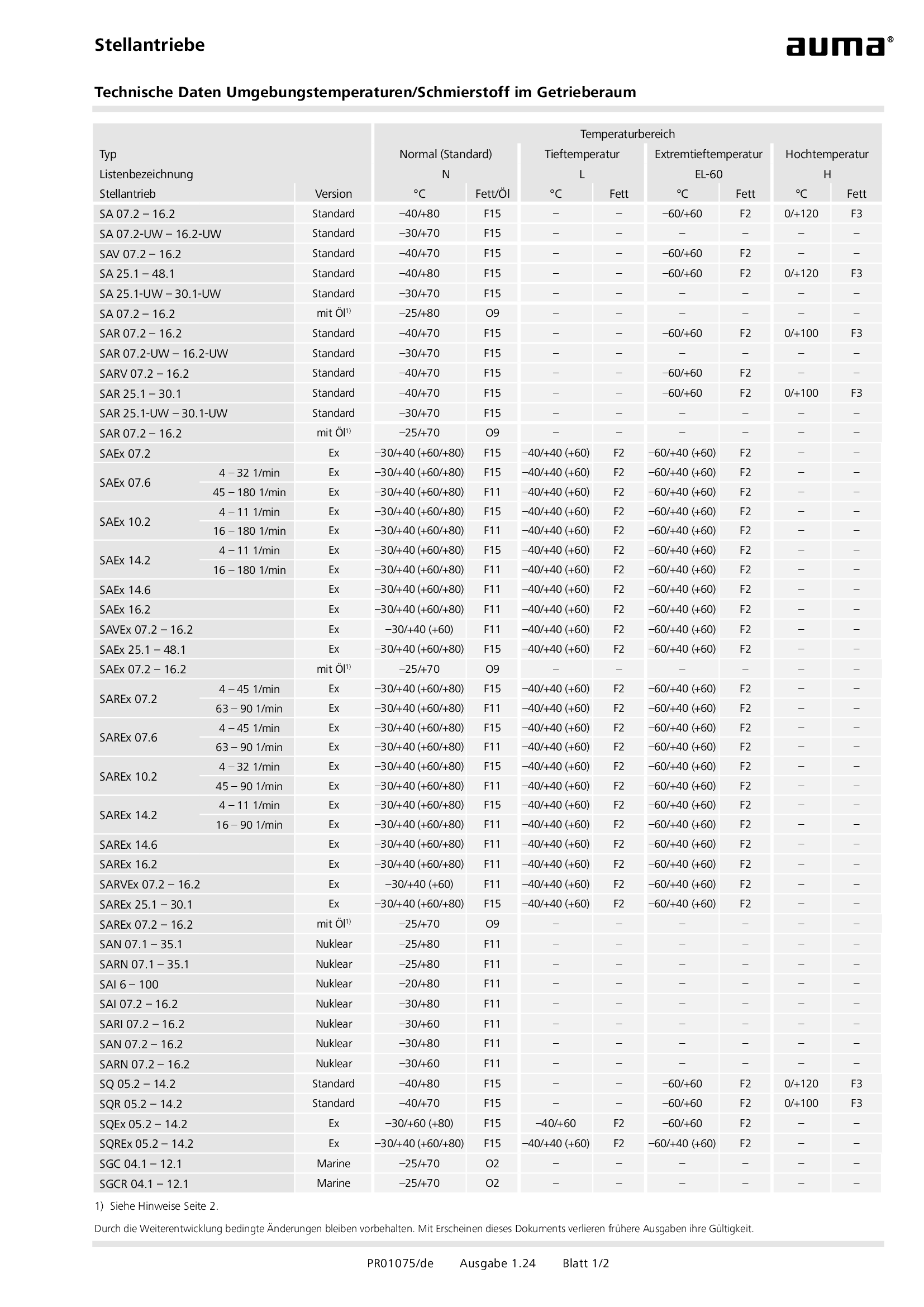
Actuators, Technical data Ambient temperatures/lubricant in the gear housing
Technical data

Gearboxes, Output drives, Technical data Ambient temperatures/lubricant in the gear housing
Technical data
Technical description
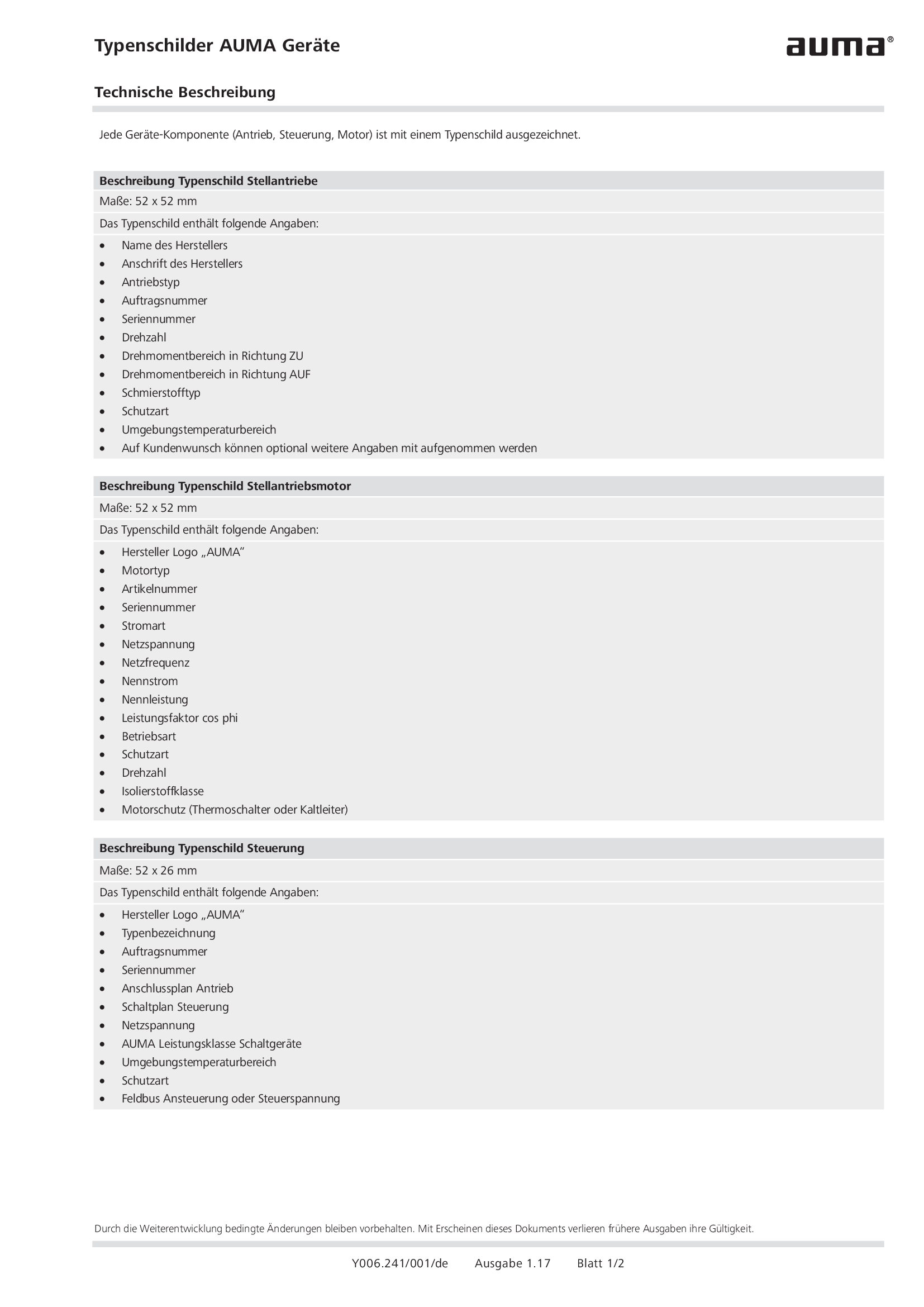
Name plates AUMA devices
Technical description
Wiring diagram

A1: AUMATIC AC 01.2 position feedback signal 0/4 - 20 mA (potentiometer in actuator), basic version, reversing contactors OPEN, STOP, CLOSE, EMERGENCY (24 V DC), 6 programmable output contacts, AUMA power class A1 - A3
Wiring diagram

A1: AUMATIC ACExC 01.2 position feedback signal 0/4 - 20 mA (potentiometer in actuator),basic version, reversing contactors CLOSE, OPEN, STOP, EMERGENCY (24 V DC), 6 programmable output contacts, AUMA power class A1 - A3
Wiring diagram

A1N: AUMATIC AC 01.2 position/torque feedback signal 0/4 - 20 mA (MWG in actuator), reversing contactors OPEN, STOP, CLOSE, EMERGENCY (24 V DC), 6 programmable output contacts, AUMA power class A1 - A3
Wiring diagram

A1N: AUMATIC ACExC 01.2 position/torque feedback signal 0/4 - 20 mA (MWG in actuator), reversing contactors CLOSE, OPEN, STOP, EMERGENCY (24 V DC), 6 programmable output contacts, AUMA power class A1 - A3
Wiring diagram

A2: AUMATIC AC 01.2 positioner and postition feedback signal 0/4 - 20 mA (potentiometer in actuator), reversing contactors OPEN, STOP, CLOSE, EMERGENCY, MODE (24 V DC), 6 programmable output contacts, AUMA power class A1 - A3
Wiring diagram

A2: AUMATIC ACExC 01.2 positioner and position feedback signal 0/4 - 20 mA (potentiometer in actuator), reversing contactors MODE, CLOSE, OPEN, STOP, EMERGENCY (24 V DC), setpoint (0/4 - 20 mA), 6 programmable output contacts, AUMA power class A1 -
Wiring diagram

A2DP: AUMATIC AC 01.2 position feedback (potentiometer in actuator), basic version, reversing contactors, Profibus, AUMA power class A1 - A3
Wiring diagram

A2DP: AUMATIC ACExC 01.2 position feedback (potentiometer in actuator), basic version, reversing contactors, Profibus, AUMA power class A1 - A3
Wiring diagram

A2ENIP: AUMATIC AC 01.2 position feedback (potentiometer in actuator), basic version, reversing contactors, Ethernet/IP, AUMA power class A3 - A3
Wiring diagram

A2ENIP: AUMATIC ACExC 01.2 position feedback (potentiometer in actuator), basic version, reversing contactors, EtherNet/IP, AUMA power class A1 - A3
Wiring diagram

A2FF: AUMATIC AC 01.2 position feedback (potentiometer in actuator), basic version, Reversing contactors, Foundation Fieldbus FF, AUMA power classes A1 – A3
Wiring diagram

A2FF: AUMATIC ACExC 01.2 position feedback (potentiometer in actuator), basic version, reversing contactors, Foundation Fieldbus FF, AUMA power class A1 - A3
Wiring diagram

A2HRT: AUMATIC AC 01.2 position feedback (potentiometer in actuator), basic version, Reversing contactors, HART actuatorAUMA power classes A1 – A3
Wiring diagram

A2HRT: AUMATIC ACExC 01.2 position feedback (potentiometer in actuator), reversing contactors, HART actuator, AUMA power class A1 - A3
Wiring diagram

A2HRTCO: AUMATIC AC 01.2 position feedback (potentiometer in actuator), basic version, Reversing contactors, HART Current Output, AUMA power classes A1 – A3
Wiring diagram

A2HRTCO: AUMATIC ACExC 01.2 position feedback (potentiometer in actuator), basic version, reversing contactors, HART current output, AUMA power class A1 - A3
Wiring diagram

A2MB: AUMATIC AC 01.2 position feedback (potentiometer in actuator), basic version, reversing contactors, Modbus RTU, AUMA power class A1 - A3
Wiring diagram

A2MB: AUMATIC ACExC 01.2 position feedback (potentiometer in acuator), basic version, reversing contactors, Modbus, AUMA power class A1 - A3
Wiring diagram

A2MBTCP: AUMATIC AC 01.2 position feedback (potentiometer in actuator), basic version, Reversing contactors, Modbus TCP/IP, AUMA power classes A1 – A3
Wiring diagram

A2MBTCP: AUMATIC AC 01.2 position/torque feedback (MWG in actuator), Reversing contactors, Modbus TCP/IP, AUMA power classes A1 – A3
Wiring diagram

A2MBTCP: AUMATIC ACExC 01.2 position feedback (potentiometer in actuator), basic version, reversing contactors, Modbus TCP/IP, AUMA power class A1 - A3
Wiring diagram

A2N: AUMATIC AC 01.2 positioner and position/torque feedback signal 0/4 - 20 mA (MWG in actuator), , reversing contactors OPEN, STOP, CLOSE, EMERGENCY, MODE (24 V DC), 6 programmable output contacts, AUMA power class A1 - A3
Wiring diagram

A2N: AUMATIC ACExC 01.2 positioner and position/torque feedback signal 0/4 - 20 mA (MWG in actuator), reversing contactors MODE, CLOSE, OPEN, STOP, EMERGENCY (24 V DC), 6 programmable output contacts, AUMA power class A1 - A3
Wiring diagram