Wyniki wyszukiwania dla
"Legend AC 01.1"
Technical data
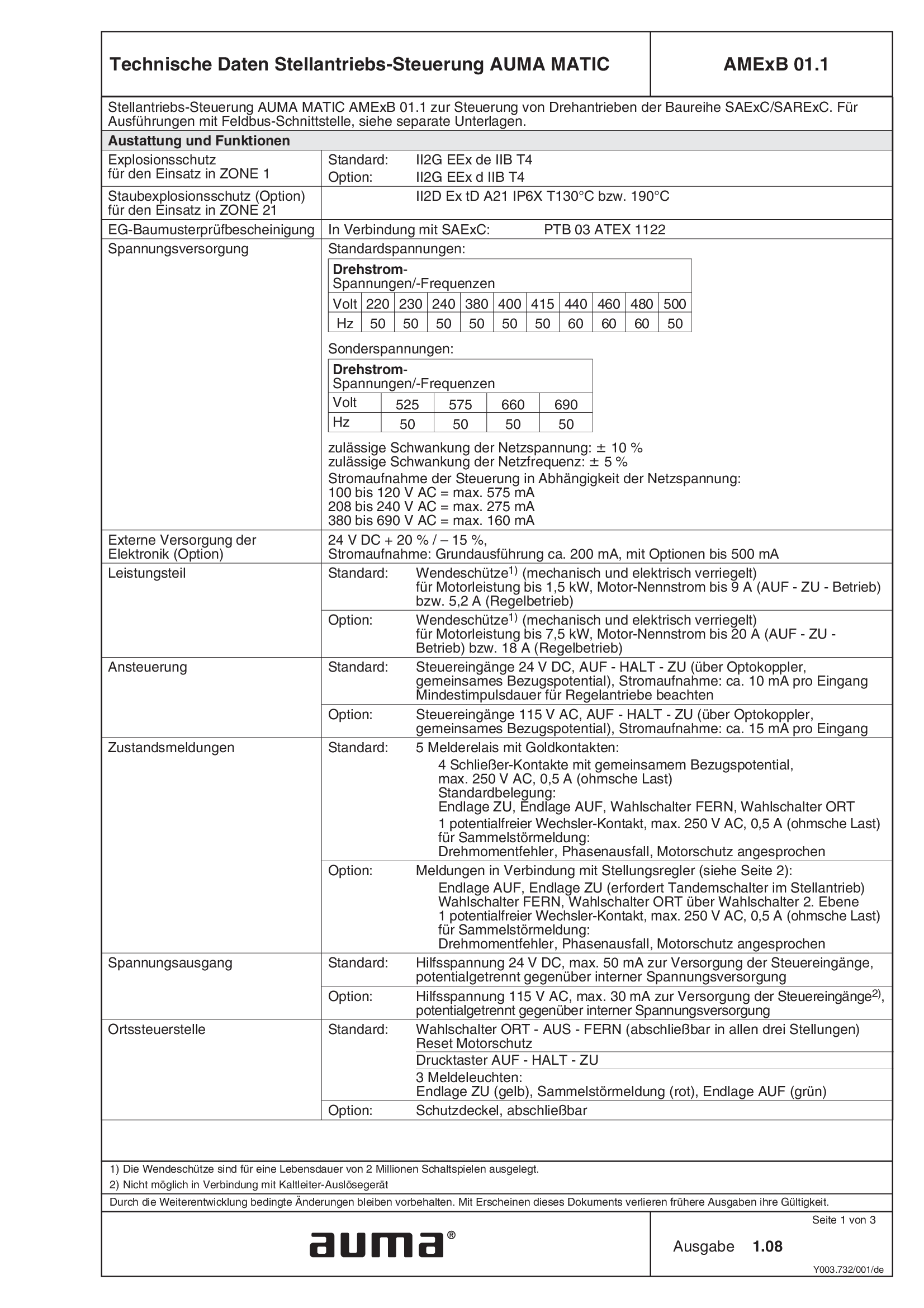
Actuator controls MATIC AMExB 01.1
Technical data
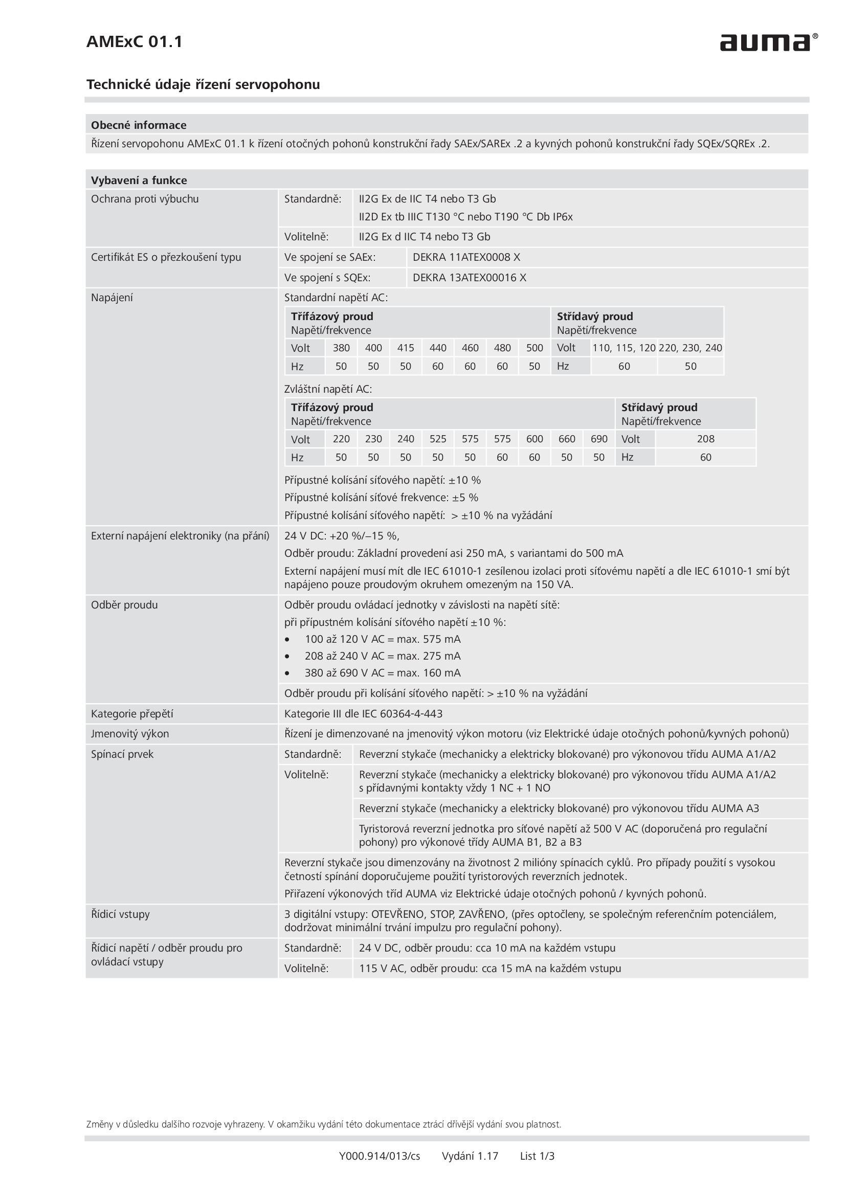
Actuator controls MATIC AMExC 01.1
Technical data
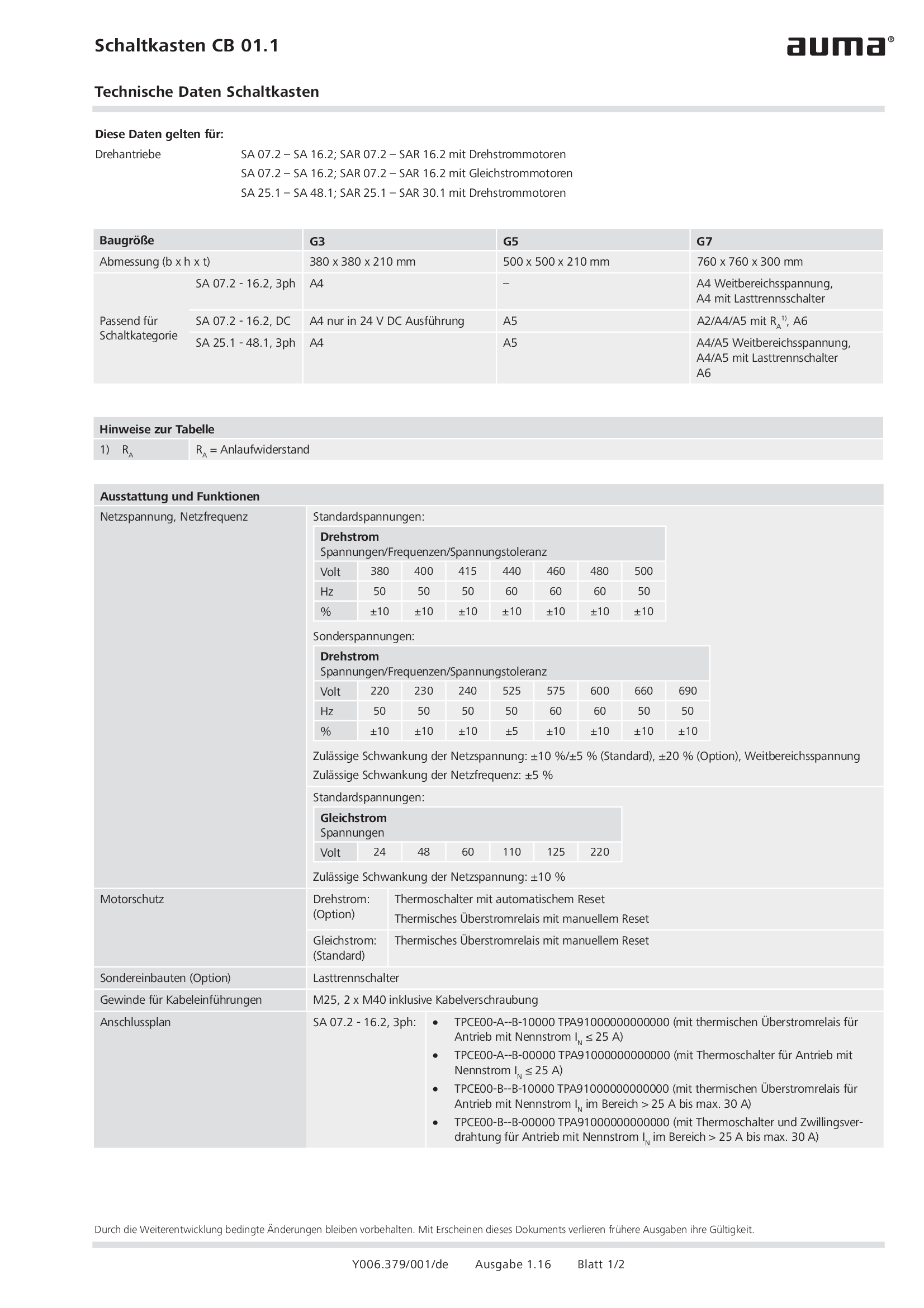
Control box CB 01.1
Technical data

Electronic position transmitter RWG 4020, EWG 01.1, Potentiometer
Technical data
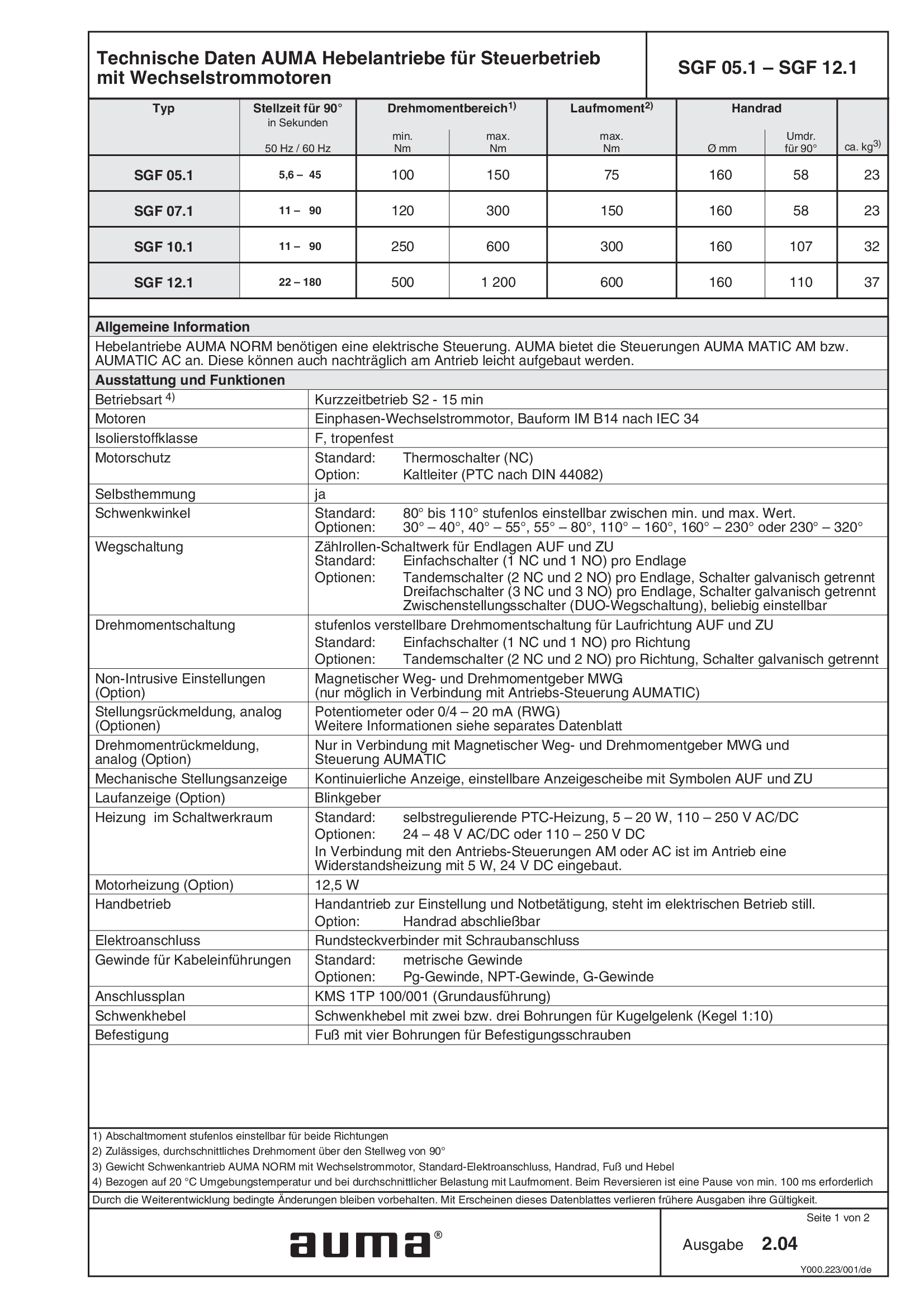
Lever actuators SGF 05.1 - 12.1, open-close duty, 1-phase AC
Technical data
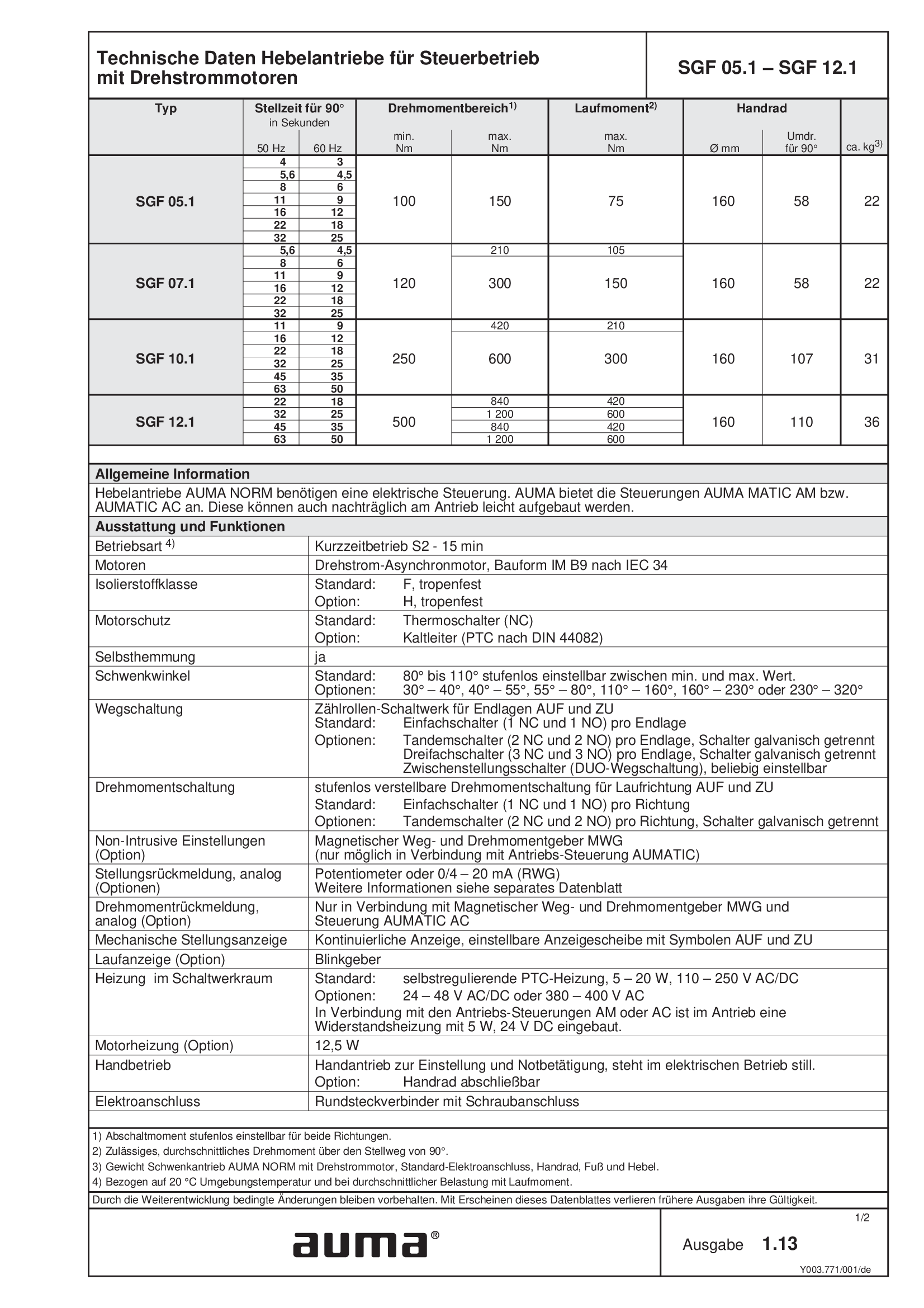
Lever actuators SGF 05.1 - 12.1, open-close duty, 3-phase AC
Technical data
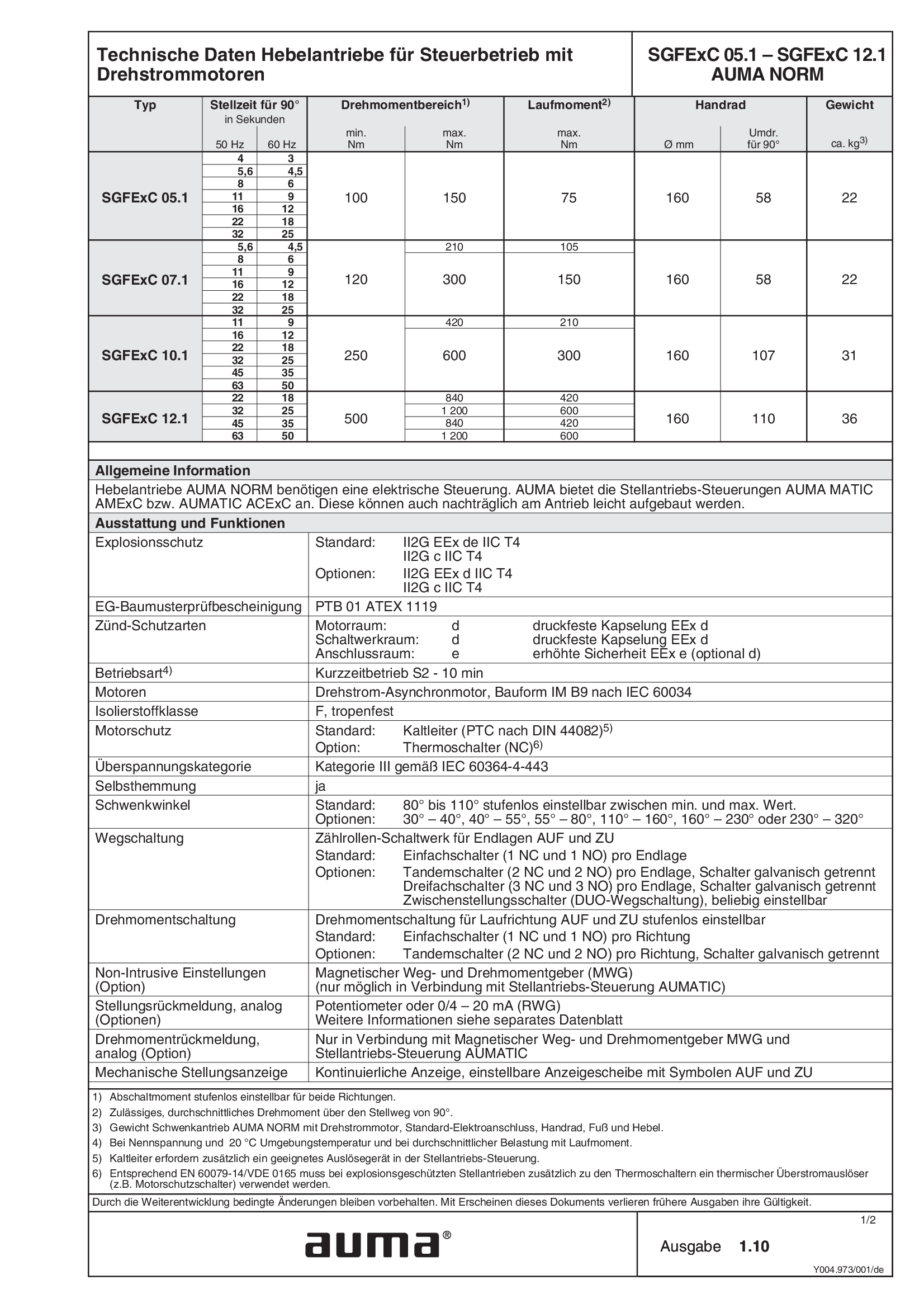
Lever actuators SGFExC 05.1 - 12.1, open-close duty, 3-phase AC
Technical data
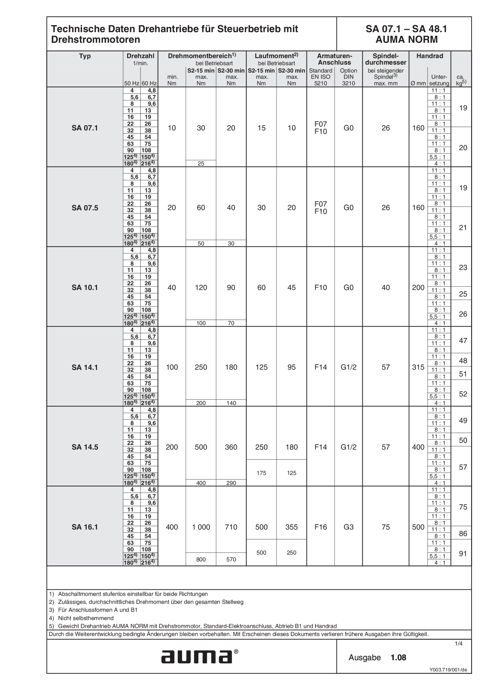
Multi-turn actuators SA 07.1 - 48.1, open-close duty, 3-phase AC
Technical data
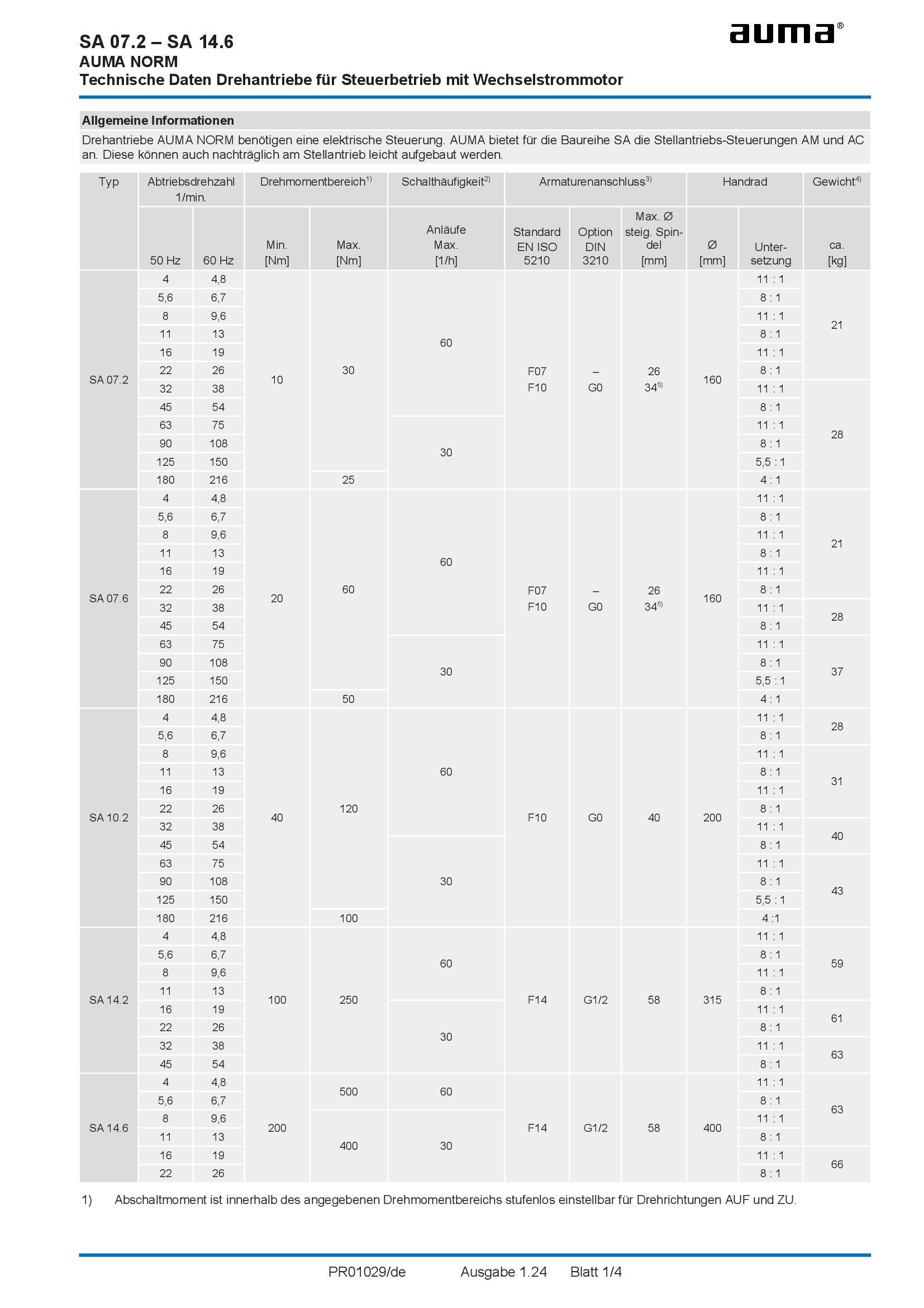
Multi-turn actuators SA 07.2 - 14.6, open-close duty, 1-phase AC
Technical data
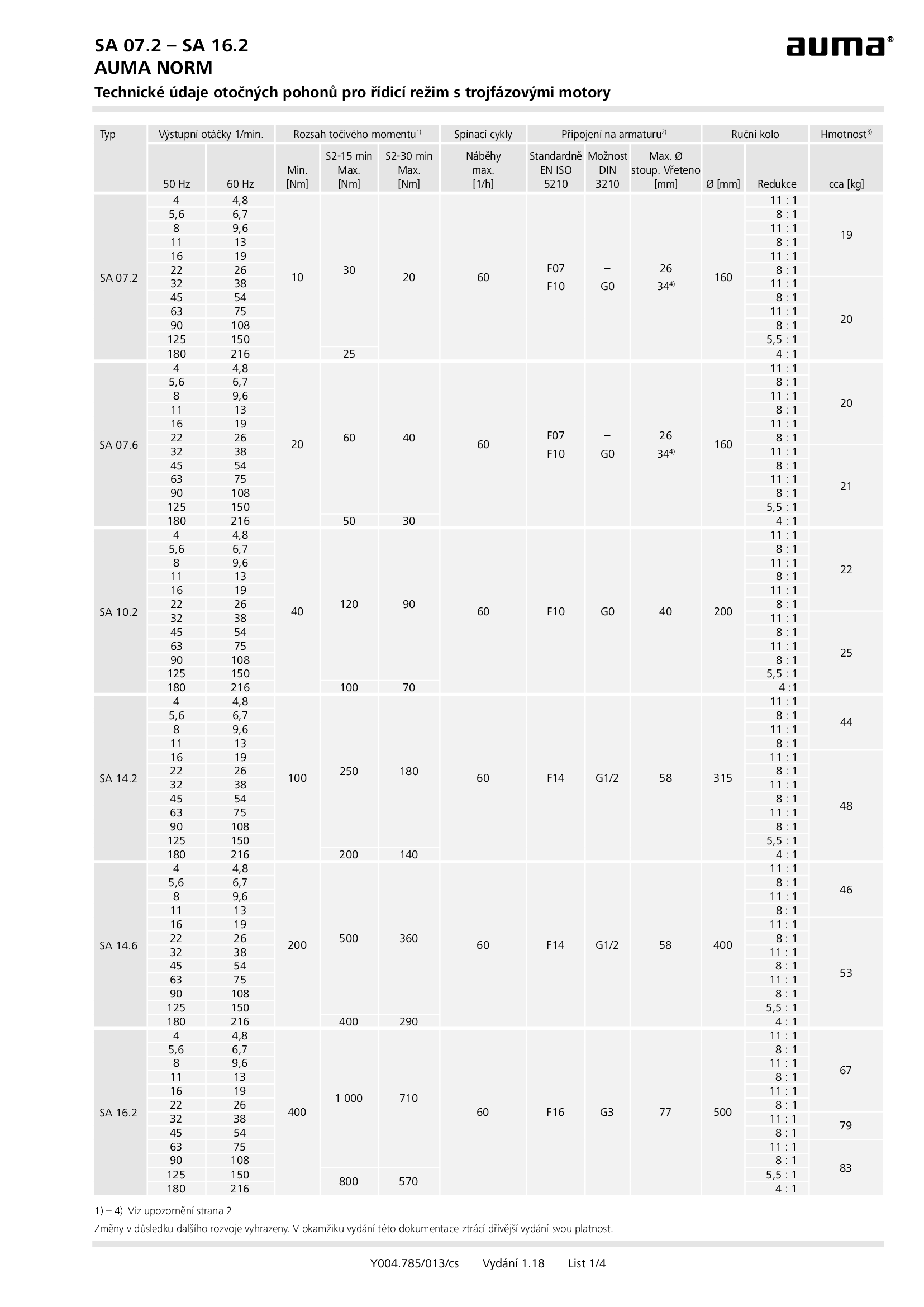
Multi-turn actuators SA 07.2 - 16.2, open-close duty, 3-phase AC
Technical data
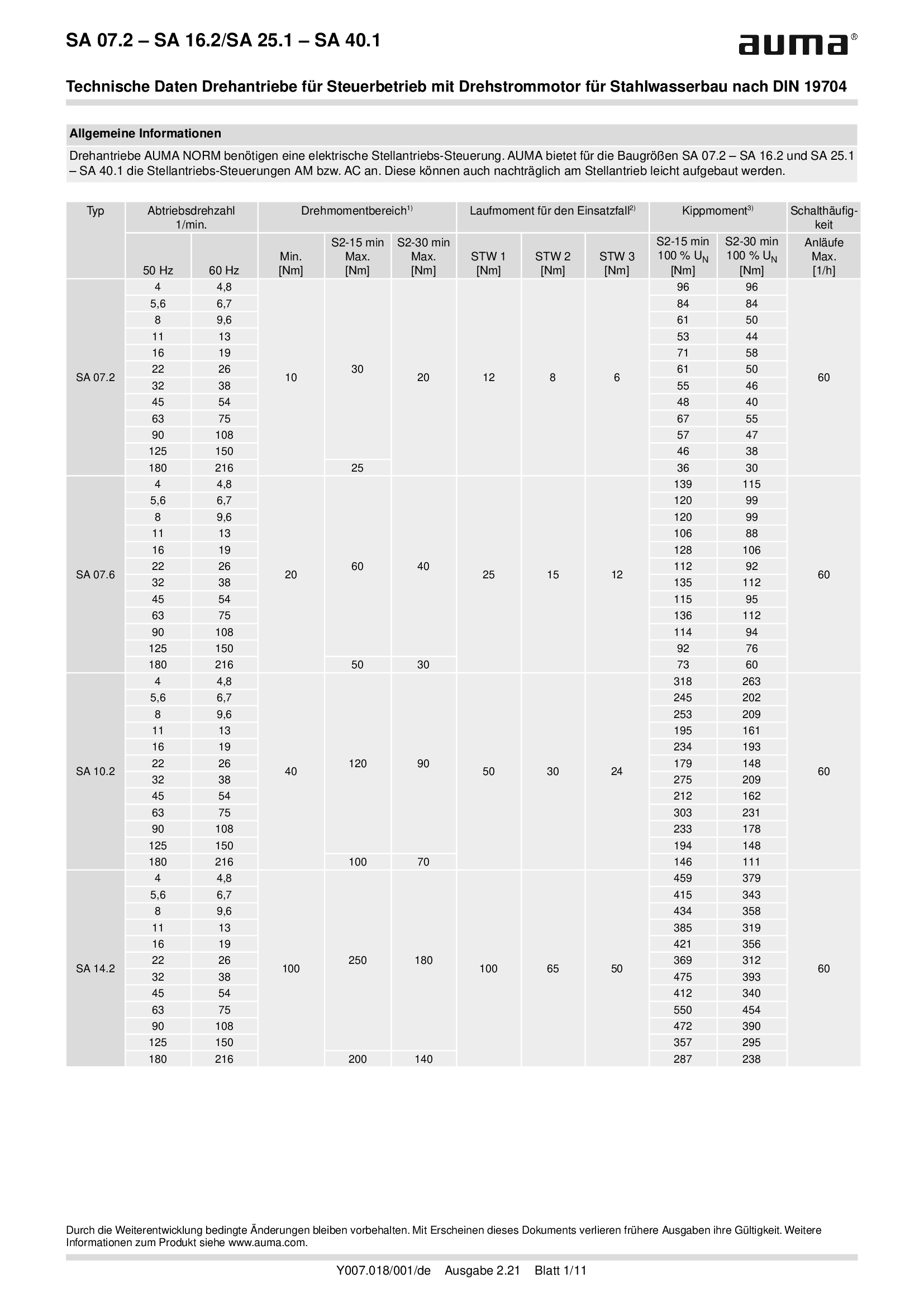
Multi-turn actuators SA 07.2 - 16.2/SA 25.1 - SA 40.1, open-close duty, 3-phase AC, for hydraulic steel structures
Technical data
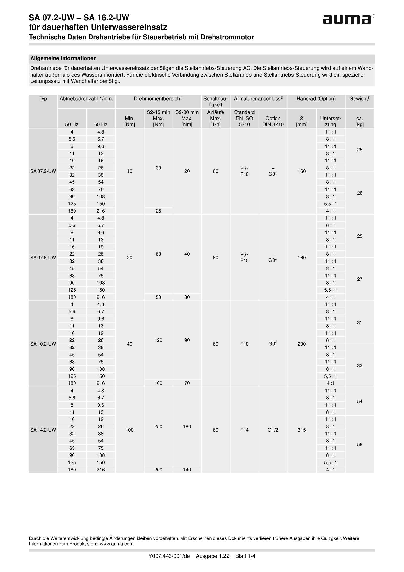
Multi-turn actuators SA 07.2-UW - SA 16.2-UW, open-close duty, 3-phase AC, for continuous underwater use
Technical data
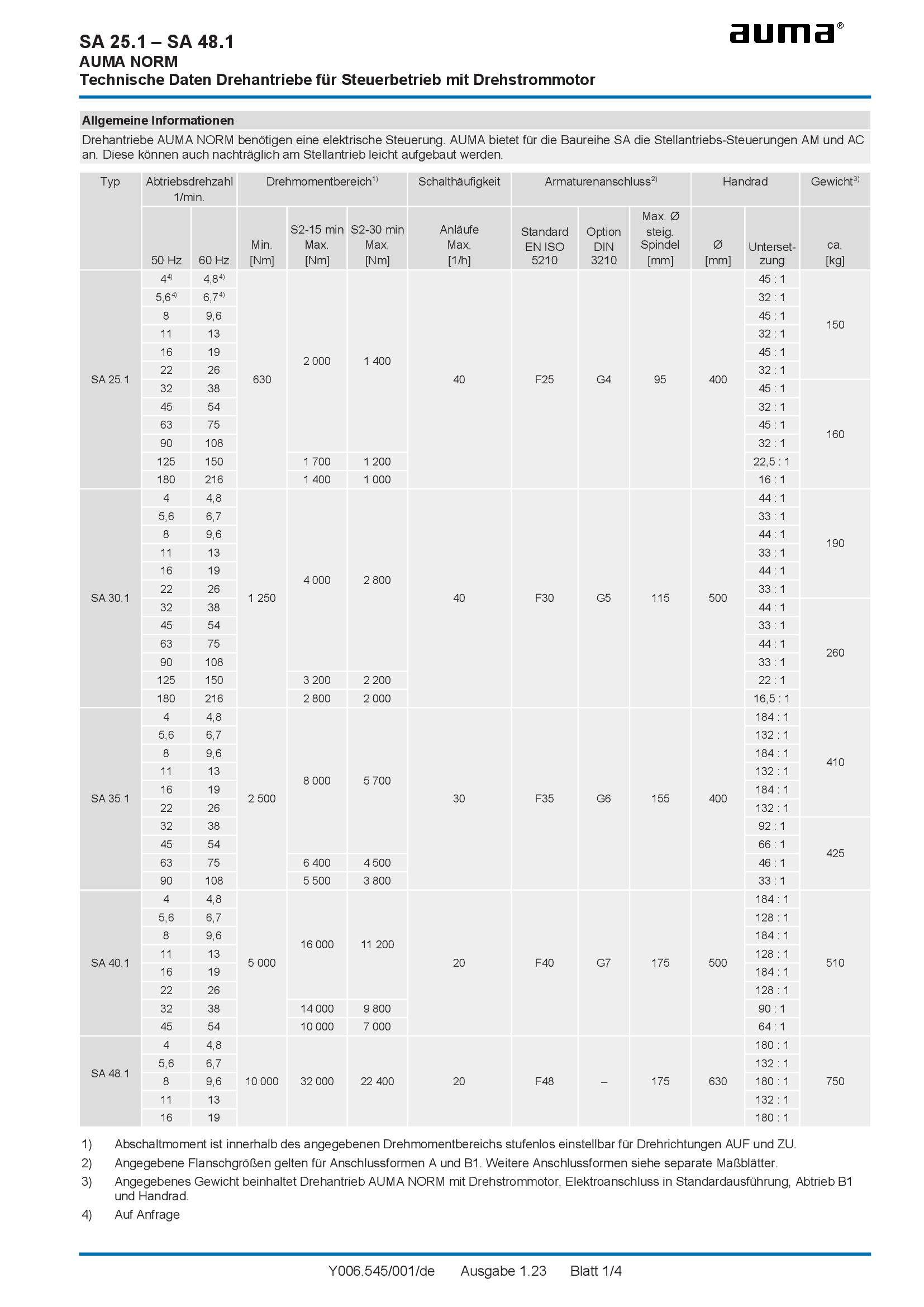
Multi-turn actuators SA 25.1 - 48.1, open-close duty, 3-phase AC
Technical data
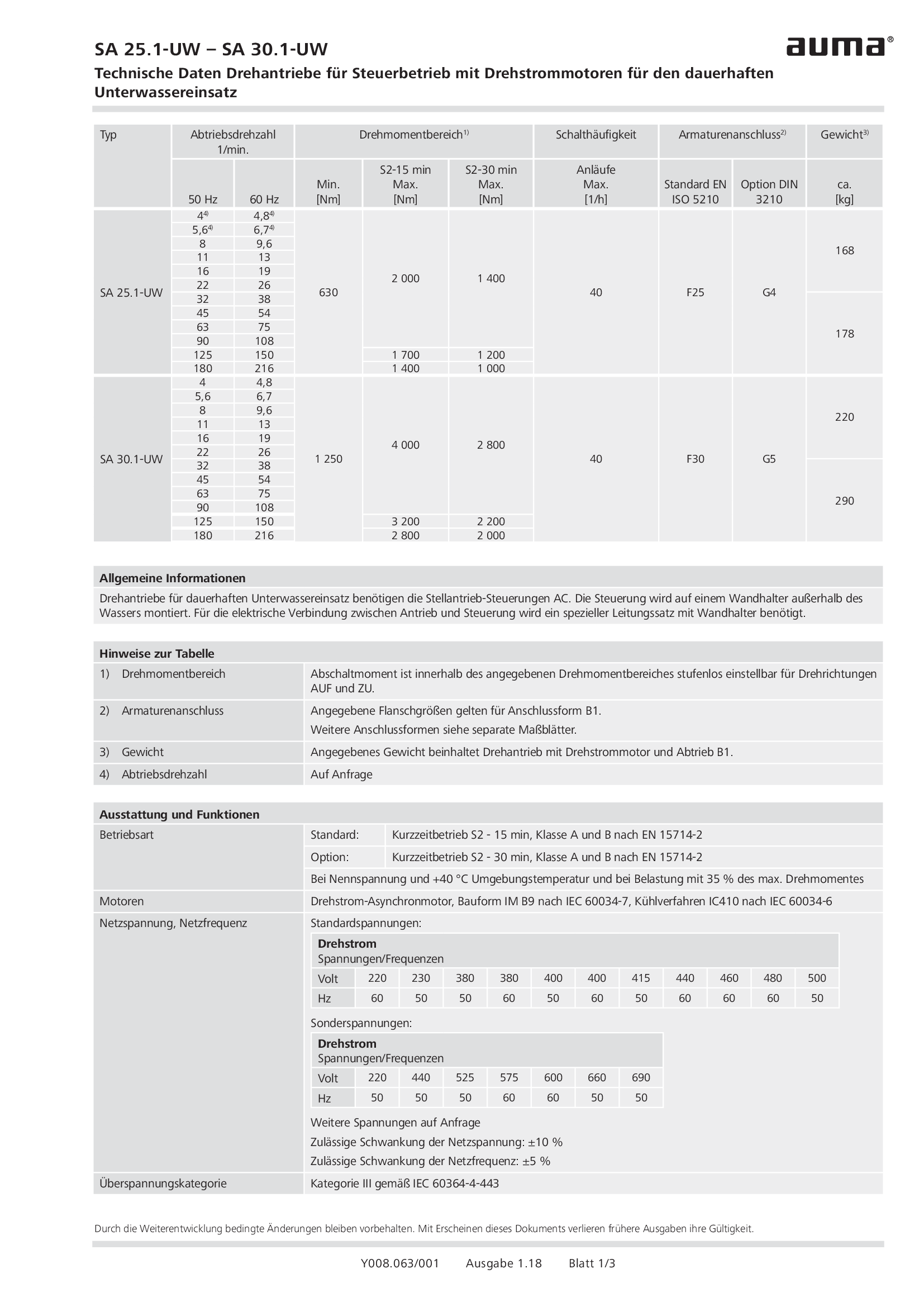
Multi-turn actuators SA 25.1-UW - SA 30.1-UW, open-close duty, 3-phase AC, for continuous underwater use
Technical data
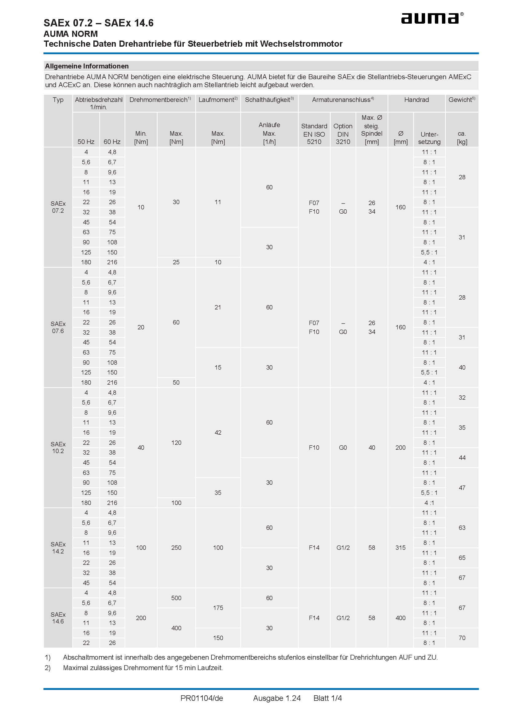
Multi-turn actuators SAEx 07.2 - 14.6, open-close duty, 1-phase AC
Technical data
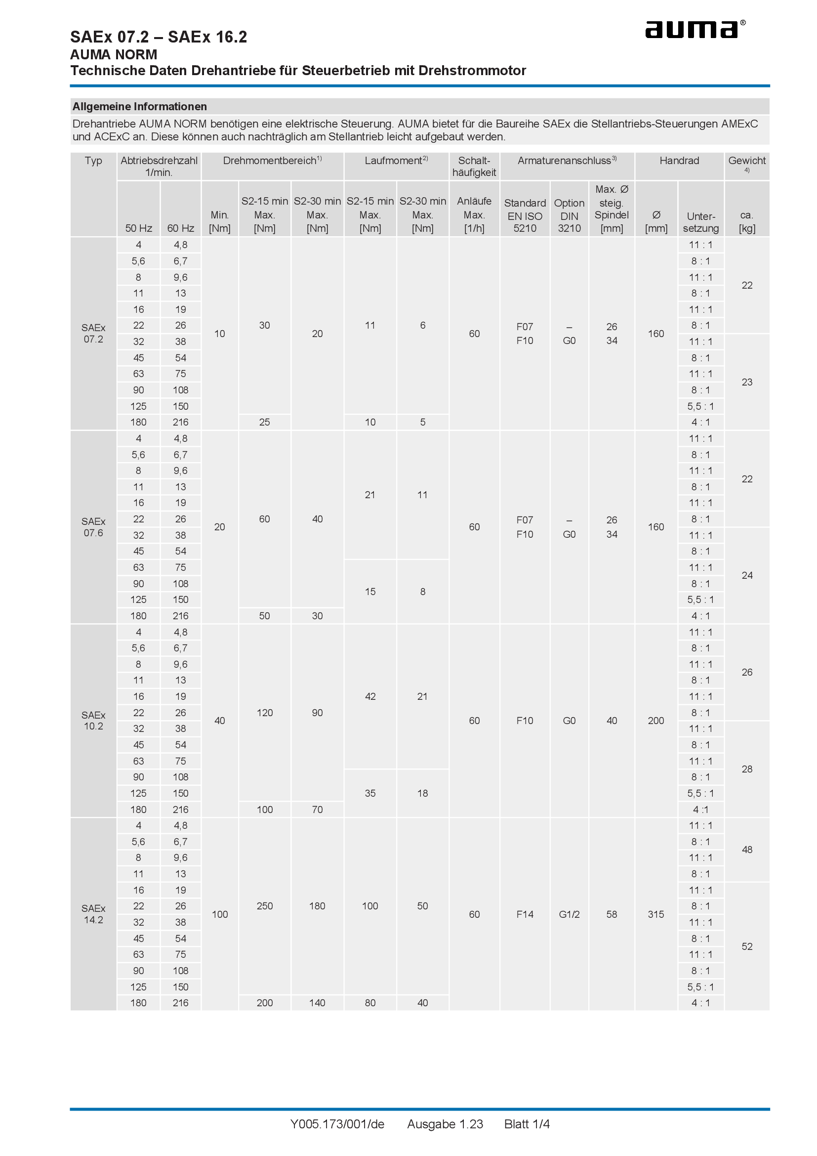
Multi-turn actuators SAEx 07.2 - 16.2, open-close duty, 3-phase AC
Technical data

Multi-turn actuators SAEx 07.2-UW - SAEx 16.2-UW, open-close duty, 3-phase AC, for continuous underwater use
Technical data

Multi-turn actuators SAEx 25.1 - 40.1, open-close duty, 3-phase AC
Technical data
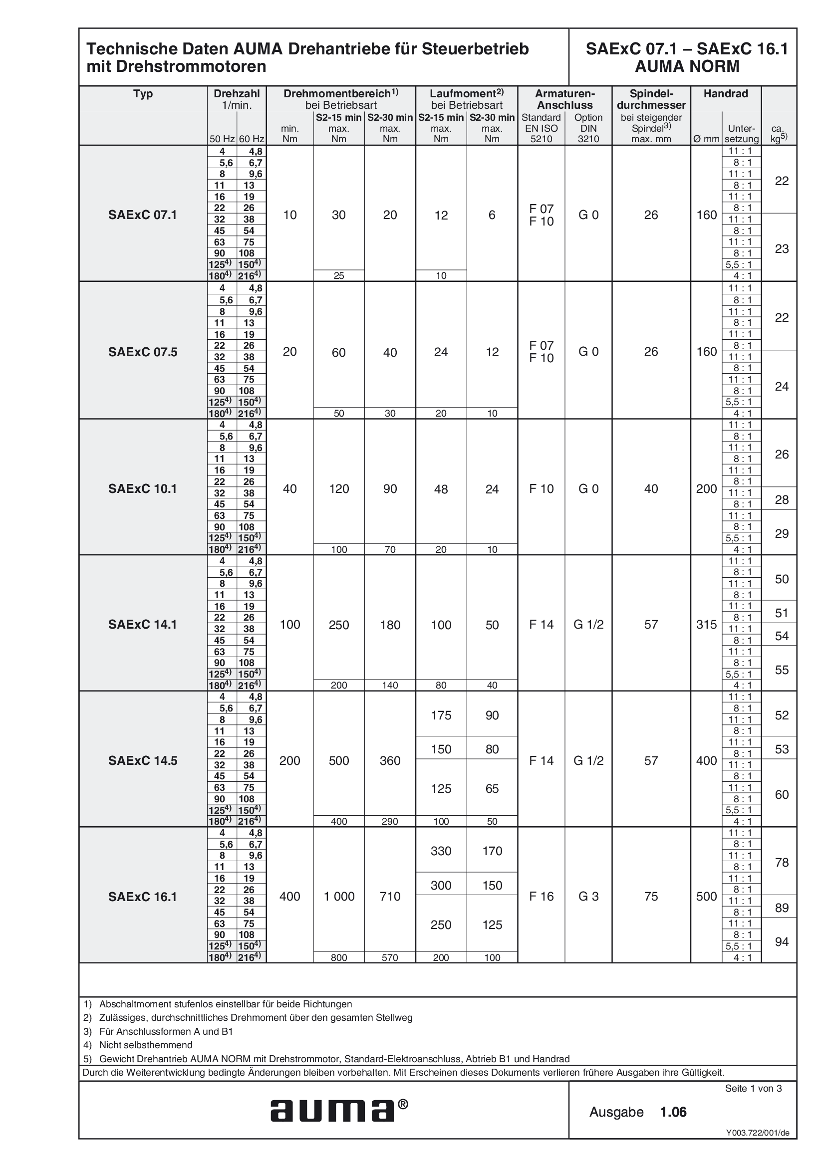
Multi-turn actuators SAExC 07.1 - 16.1, open-close duty, 3-phase AC
Technical data
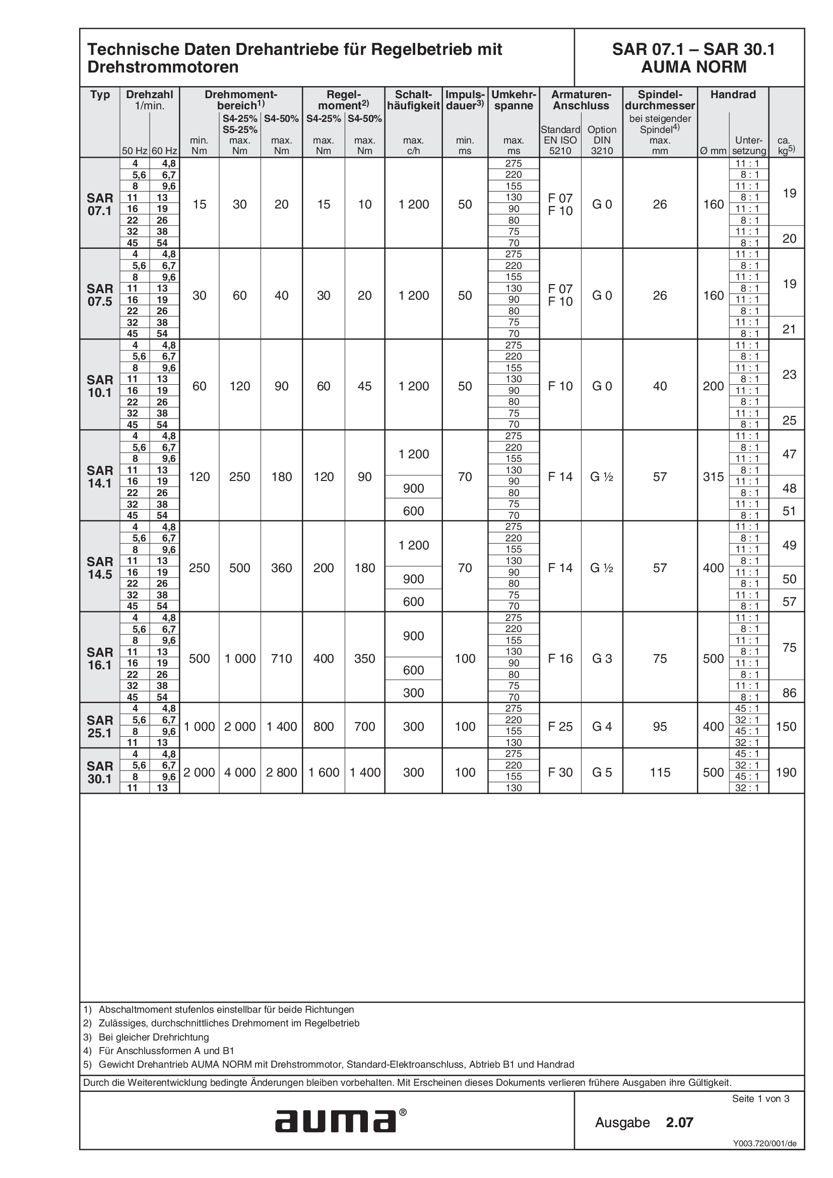
Multi-turn actuators SAR 07.1 - 30.1, modulating duty, 3-phase AC
Technical data

Multi-turn actuators SAR 07.2 - 14.6, modulating duty, 1-phase AC
Technical data
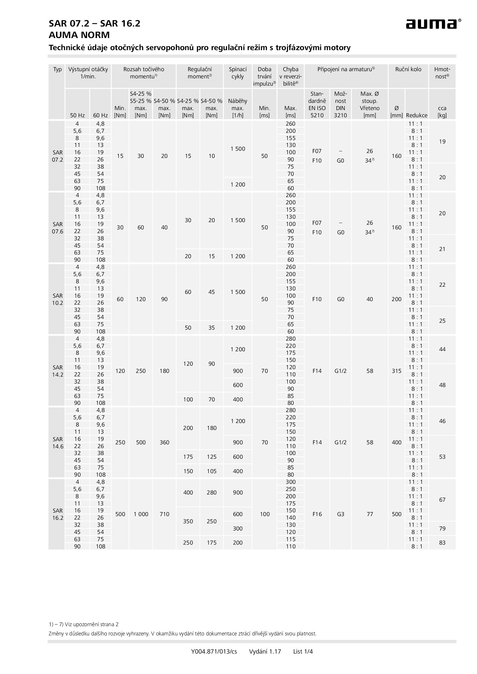
Multi-turn actuators SAR 07.2 - 16.2, modulating duty, 3-phase AC
Technical data

Multi-turn actuators SAR 07.2-UW - SAR 16.2-UW, modulatingn duty, 3-phase AC, for continuous underwater use
Technical data

Multi-turn actuators SAR 25.1 - 30.1, modulating duty, 3-phase AC
Technical data

Multi-turn actuators SAR 25.1-UW - SAR 30.1-UW, modulatingn duty, 3-phase AC, for continuous underwater use
Technical data
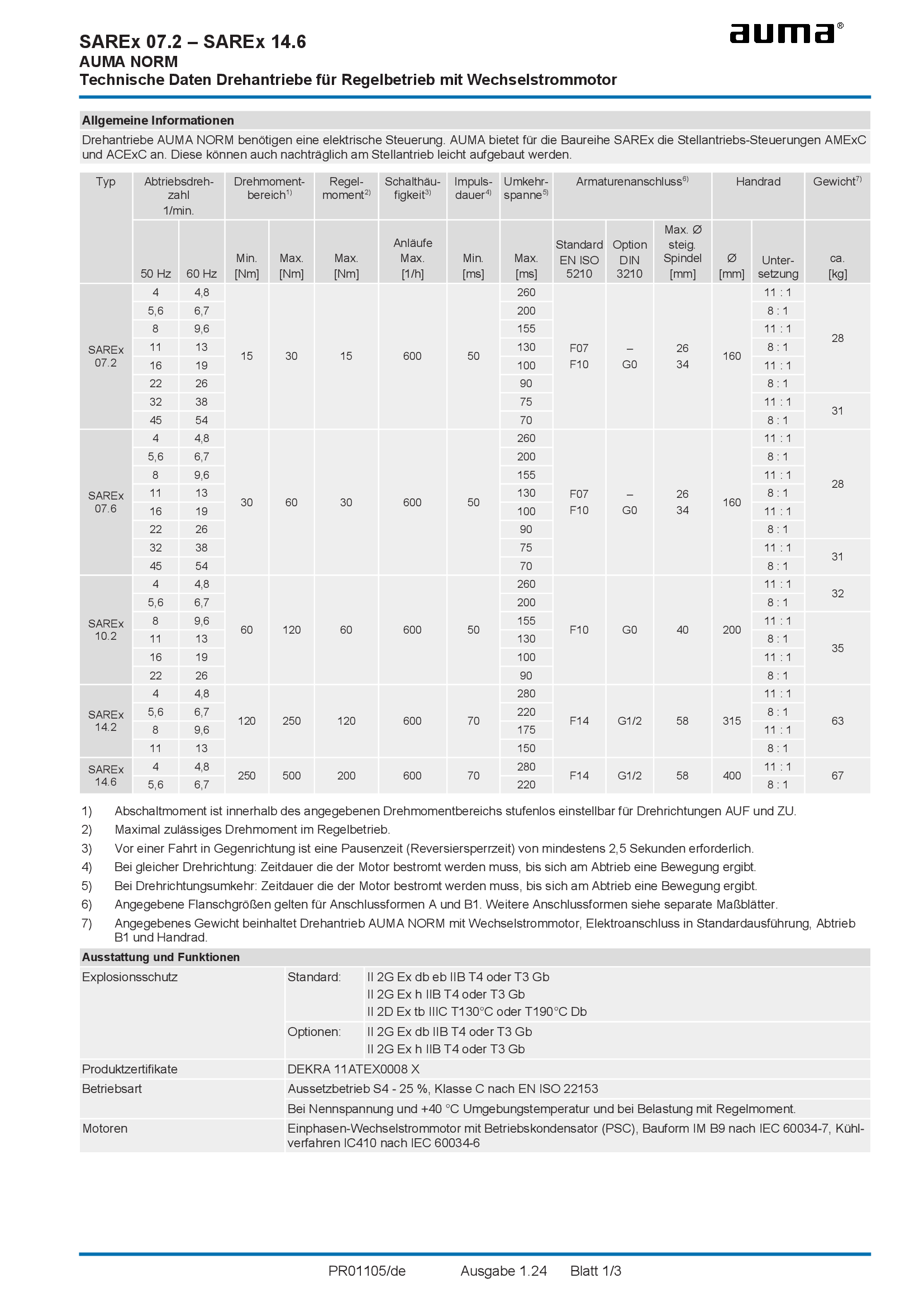
Multi-turn actuators SAREx 07.2 - 14.6, modulating duty, 1-phase AC
Technical data
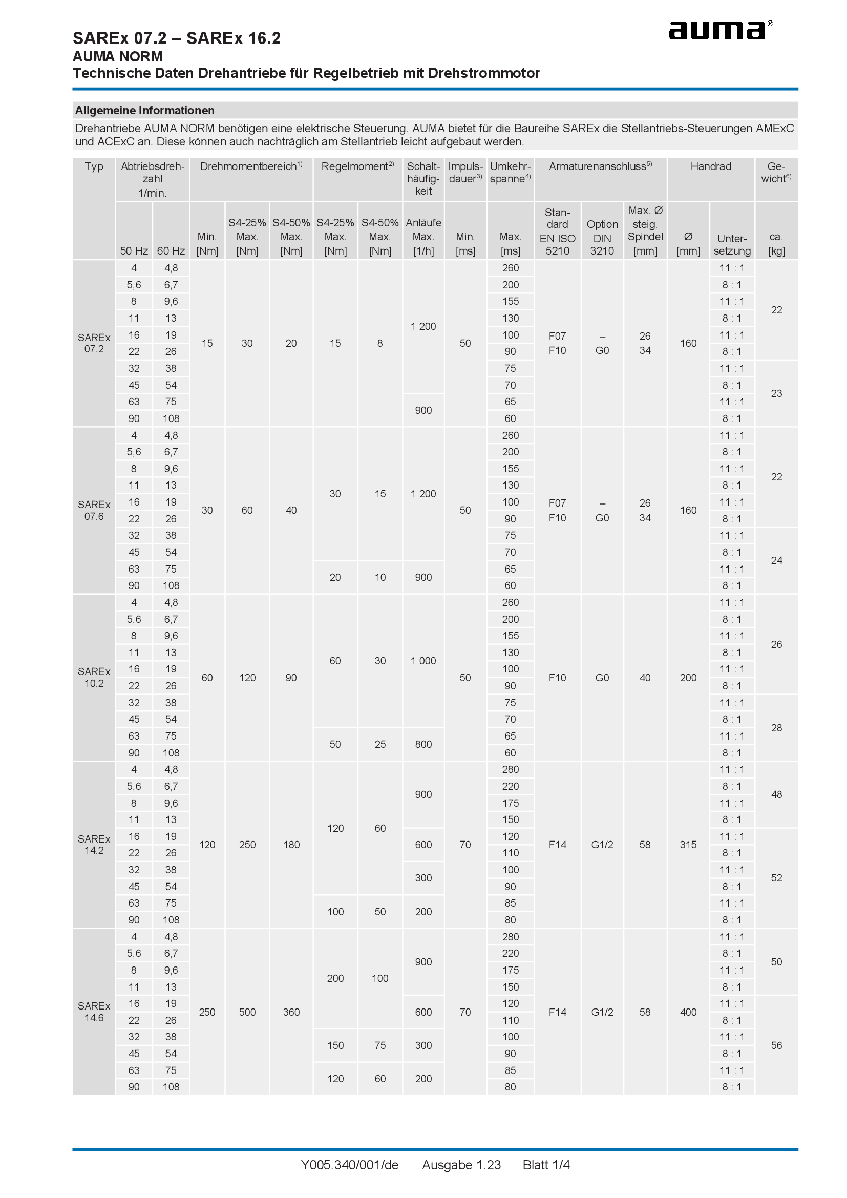
Multi-turn actuators SAREx 07.2 - 16.2, modulating duty, 3-phase AC
Technical data
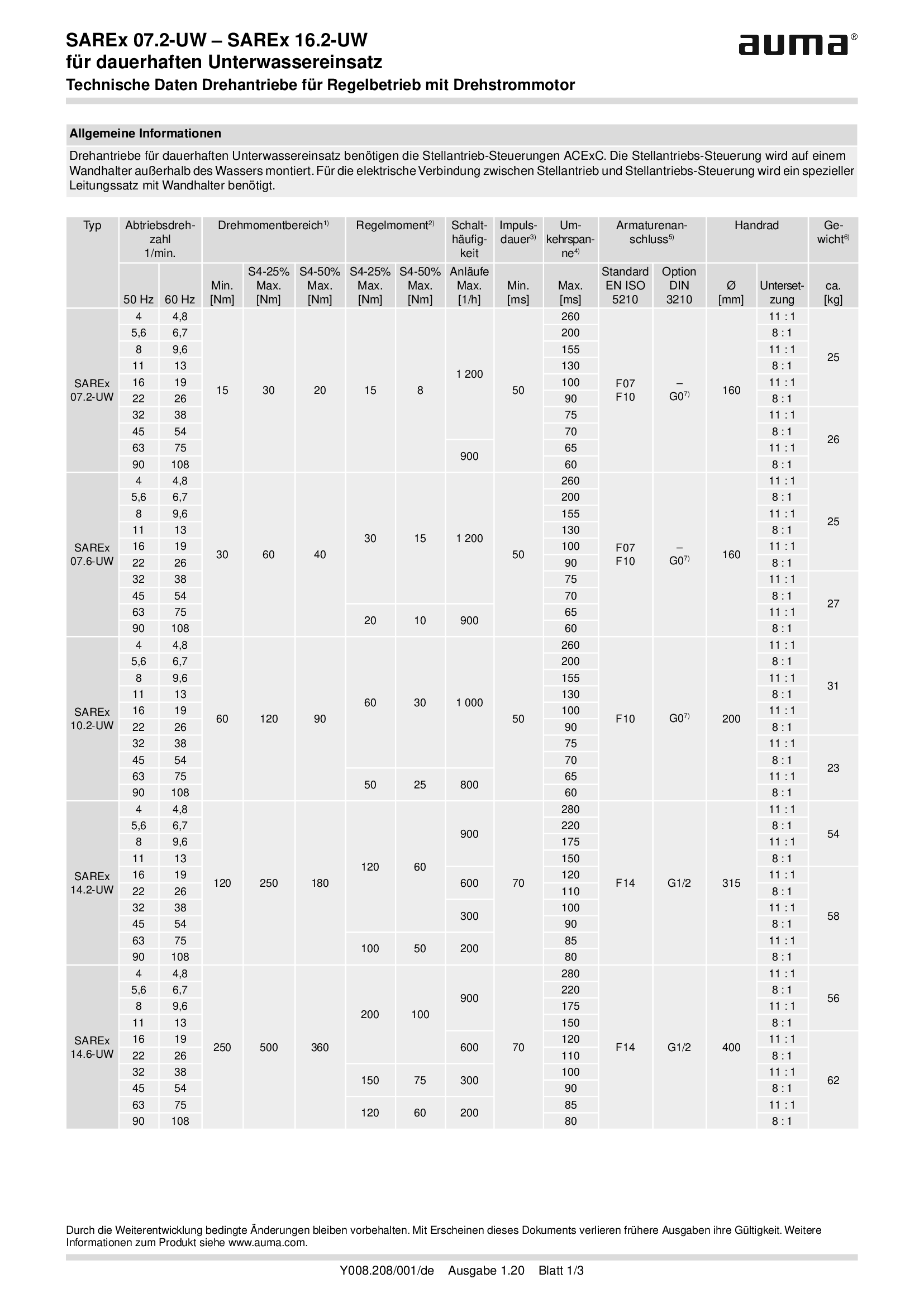
Multi-turn actuators SAREx 07.2-UW - SAREx 16.2-UW, modulatingn duty, 3-phase AC, for continuous underwater use
Technical data
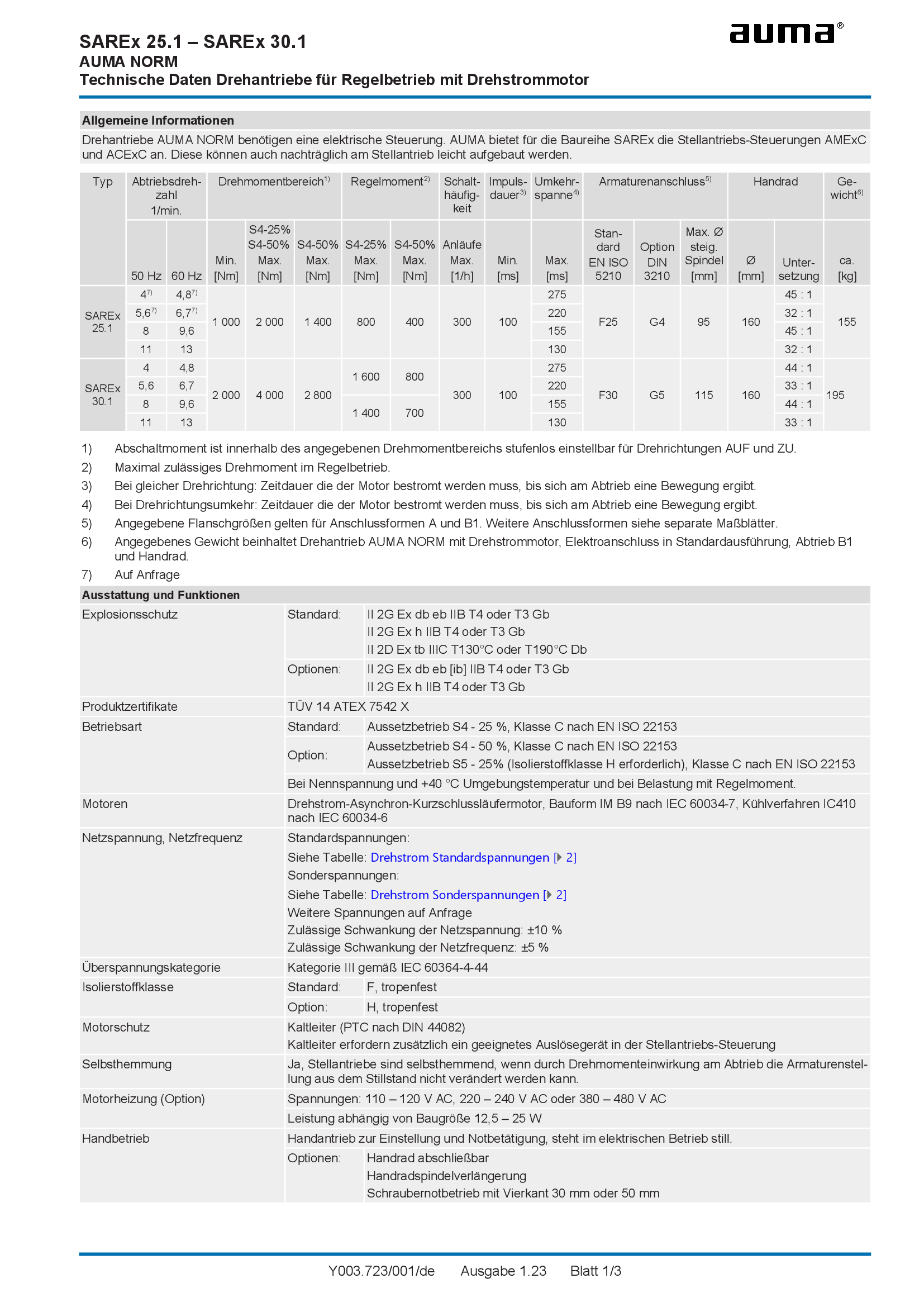
Multi-turn actuators SAREx 25.1 - 30.1, modulating duty, 3-phase AC
Technical data
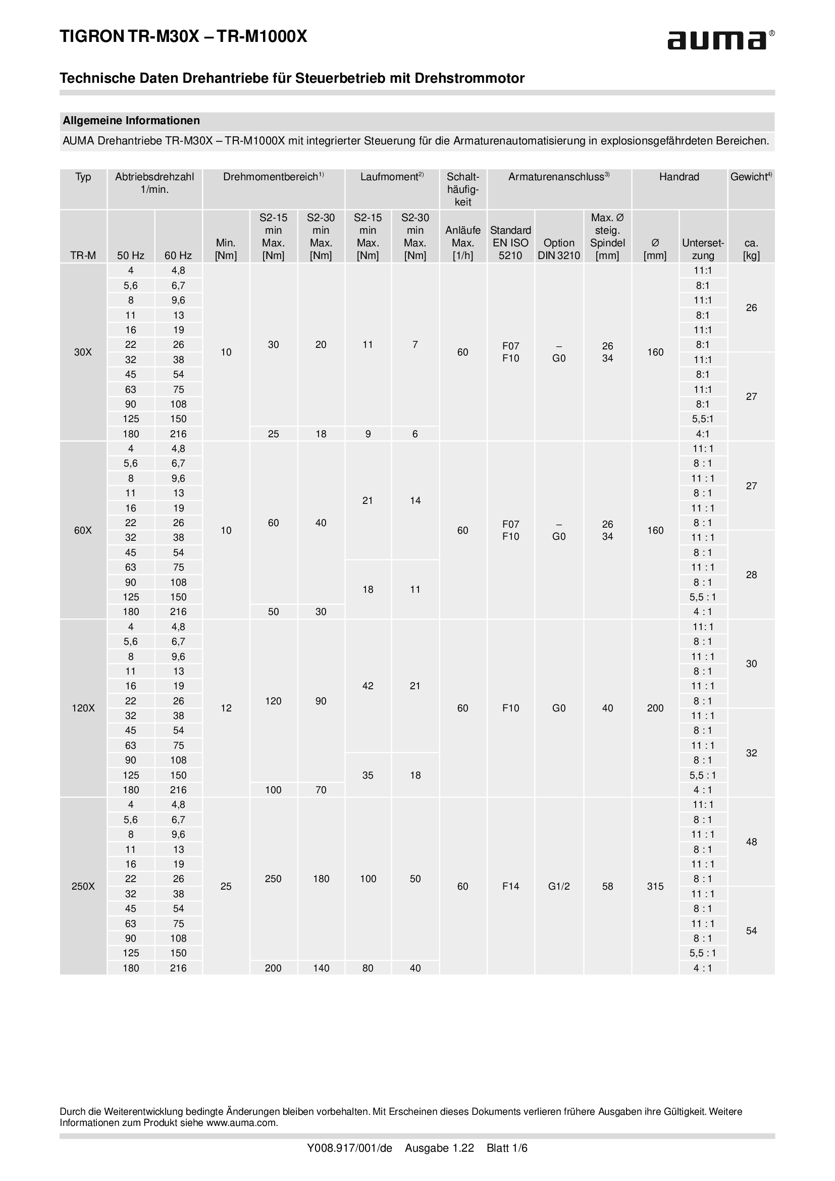
Multi-turn actuators TR-M30X - M1000X, open-close duty, 3-phase AC
Technical data
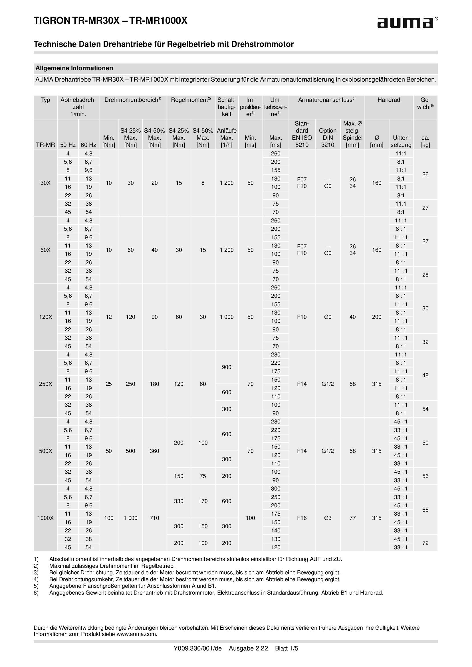
Multi-turn actuators TR-MR30X - MR1000X, modulating-duty, 3-phase AC
Technical data
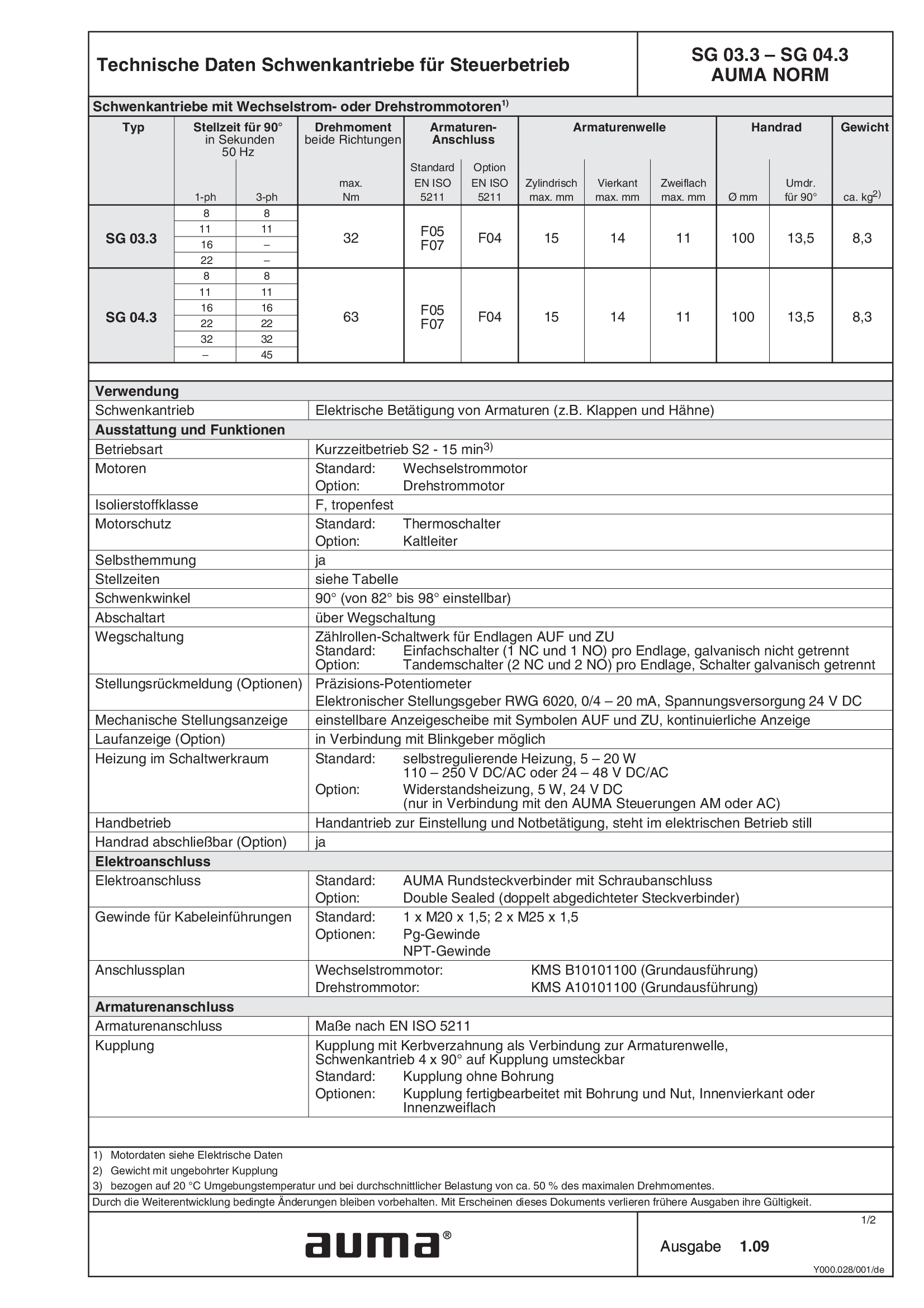
Part-turn actuators SG 03.3 - 04.3, open-close duty, 1-phase AC, 3-phase
Technical data
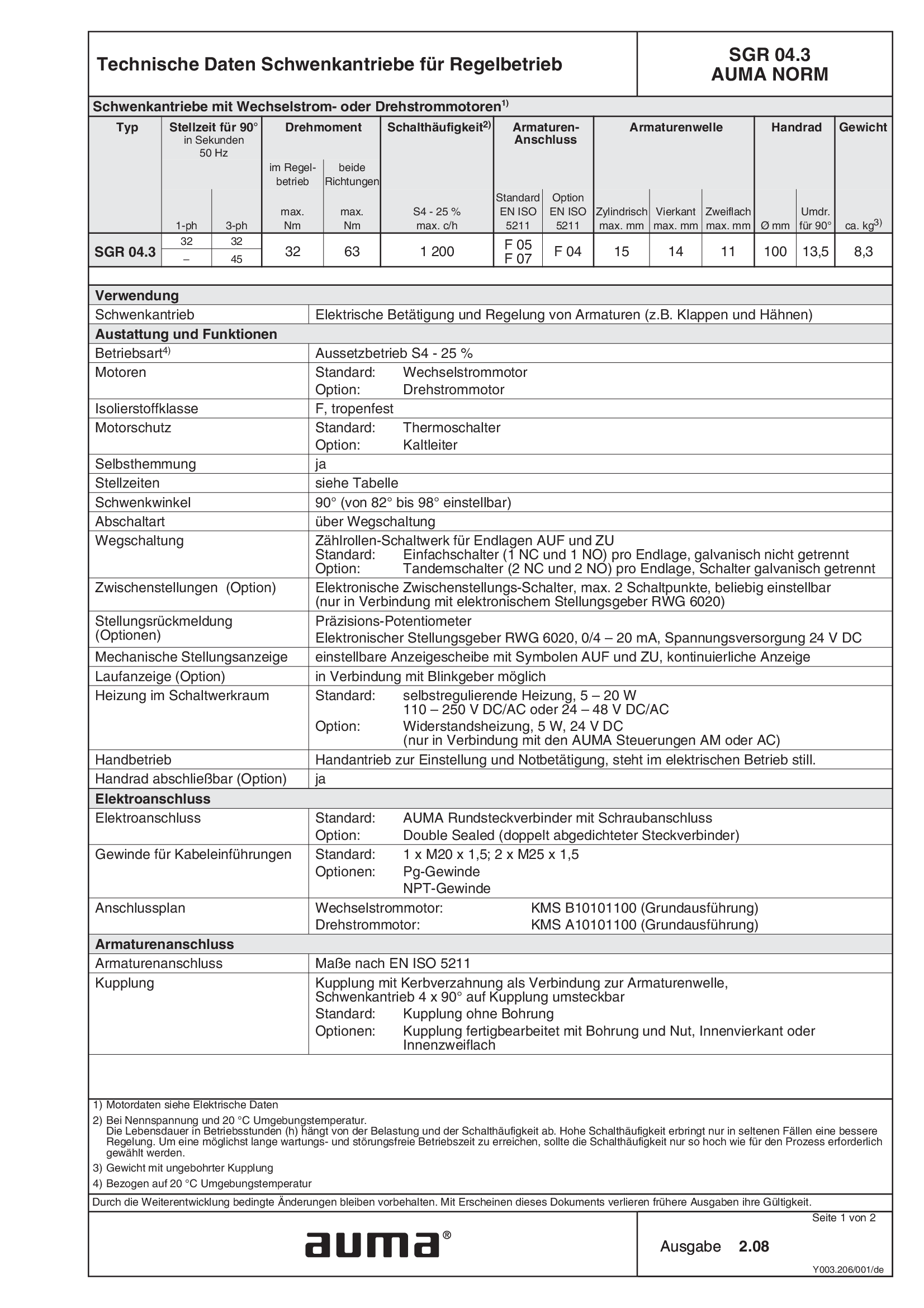
Part-turn actuators SGR 04.3, modulating duty, 1-phase AC, 3-phase
Technical data
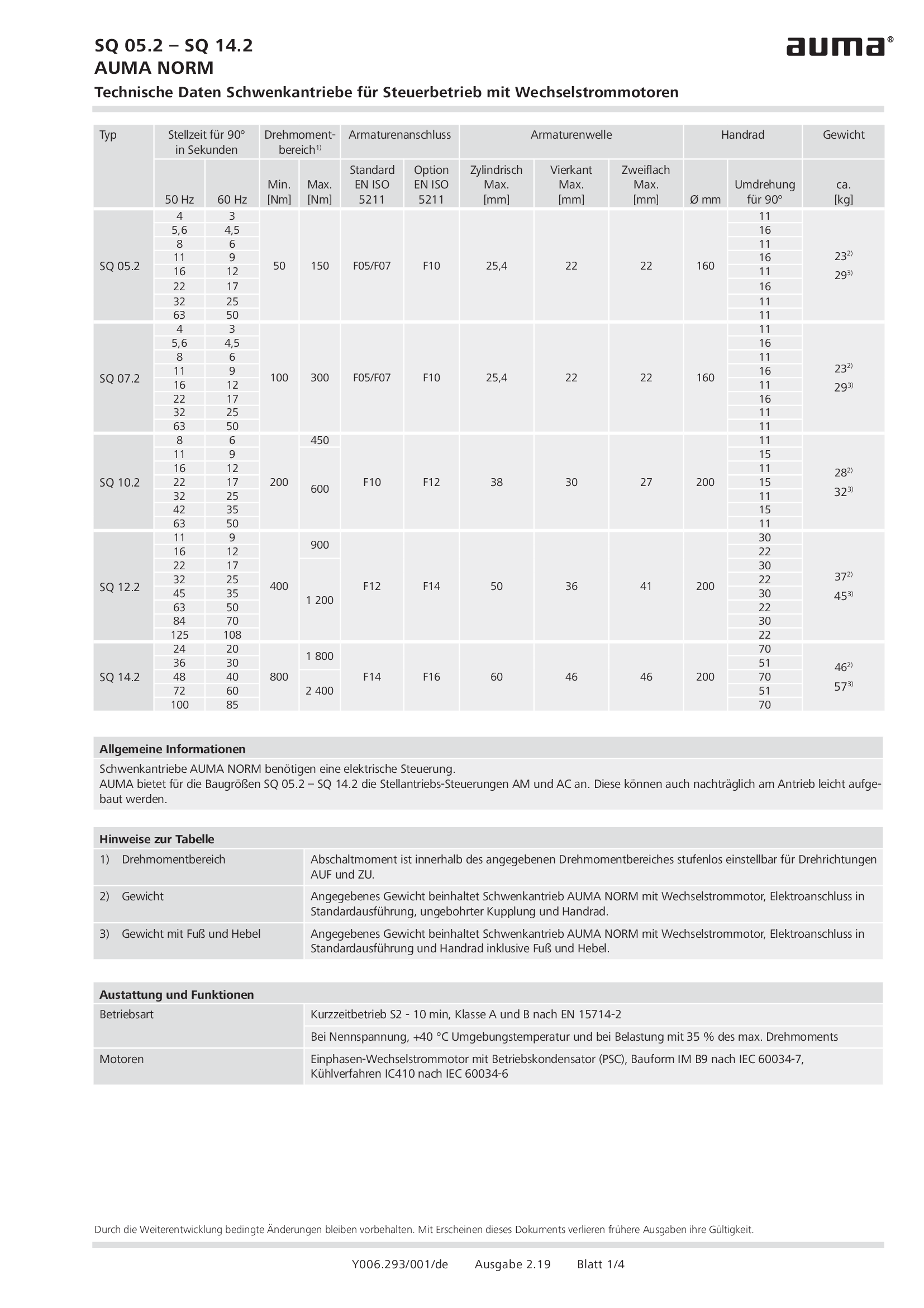
Part-turn actuators SQ 05.2 - 14.2, open-close duty, 1-phase AC
Technical data
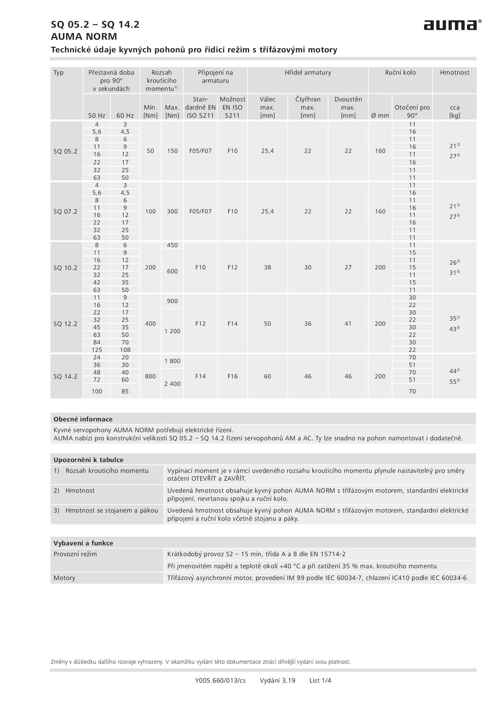
Part-turn actuators SQ 05.2 - 14.2, open-close duty, 3-phase AC
Technical data
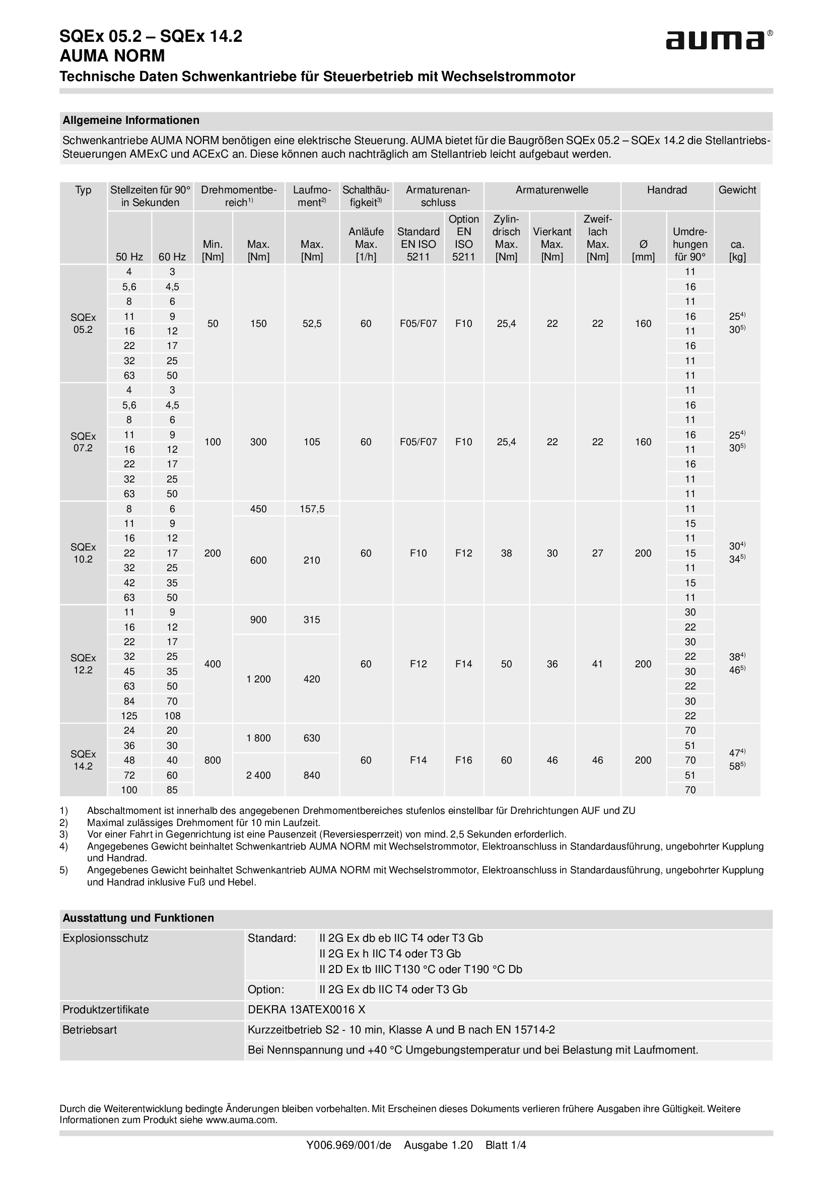
Part-turn actuators SQEx 05.2 - 14.2, open-close duty, 1-phase AC
Technical data

Part-turn actuators SQEx 05.2 - 14.2, open-close duty, 3-phase AC
Technical data

Part-turn actuators SQR 05.2 - 14.2, modulating duty, 1-phase AC
Technical data
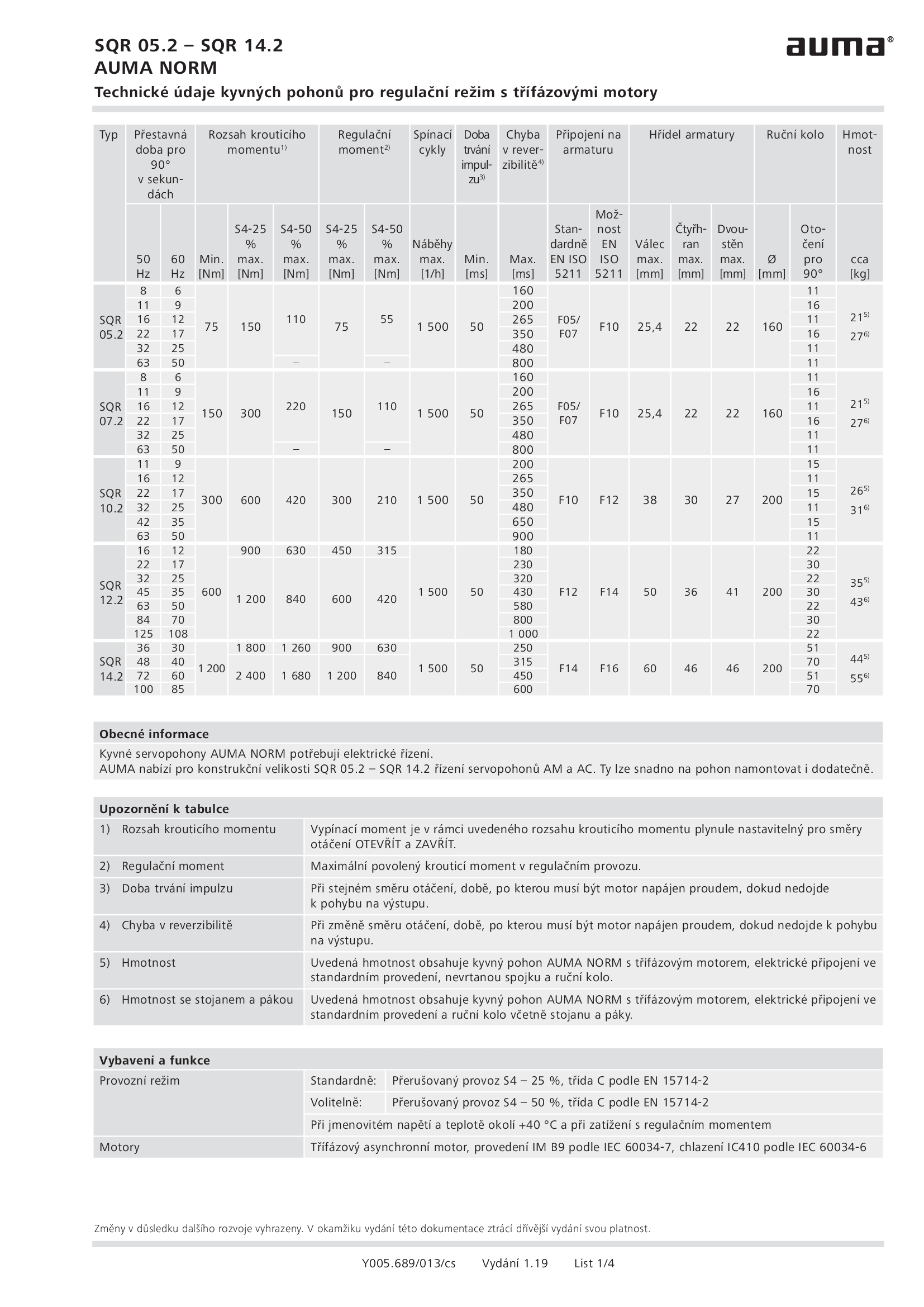
Part-turn actuators SQR 05.2 - 14.2, modulating duty, 3-phase AC
Technical data

Part-turn actuators SQREx 05.2 - 14.2, modulating duty, 1-phase AC
Technical data
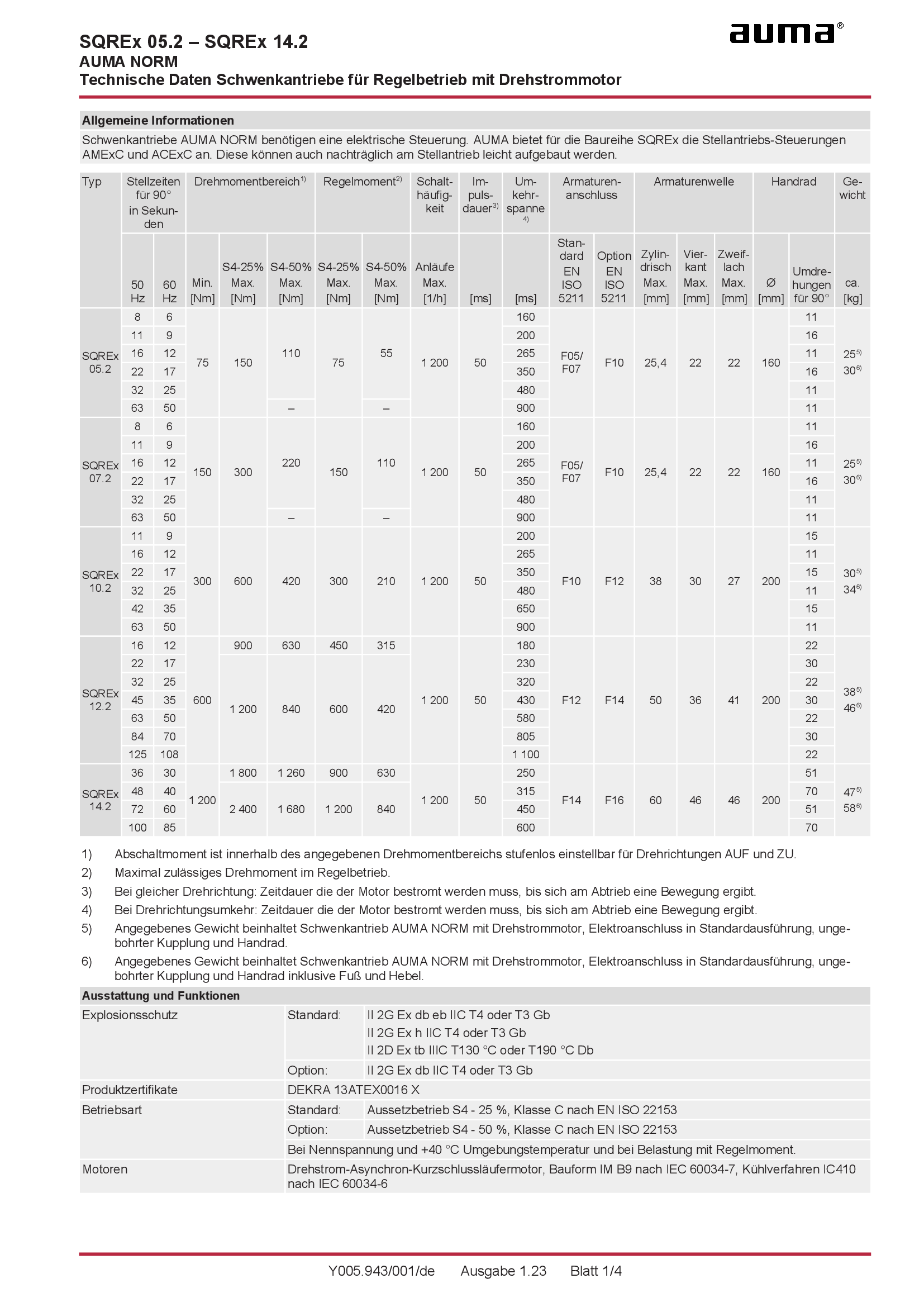
Part-turn actuators SQREx 05.2 - 14.2, modulating duty, 3-phase AC
Technical data

Part-turn actuators SQREx 05.2 - 14.2, modulating duty, 3-phase AC
Technical data
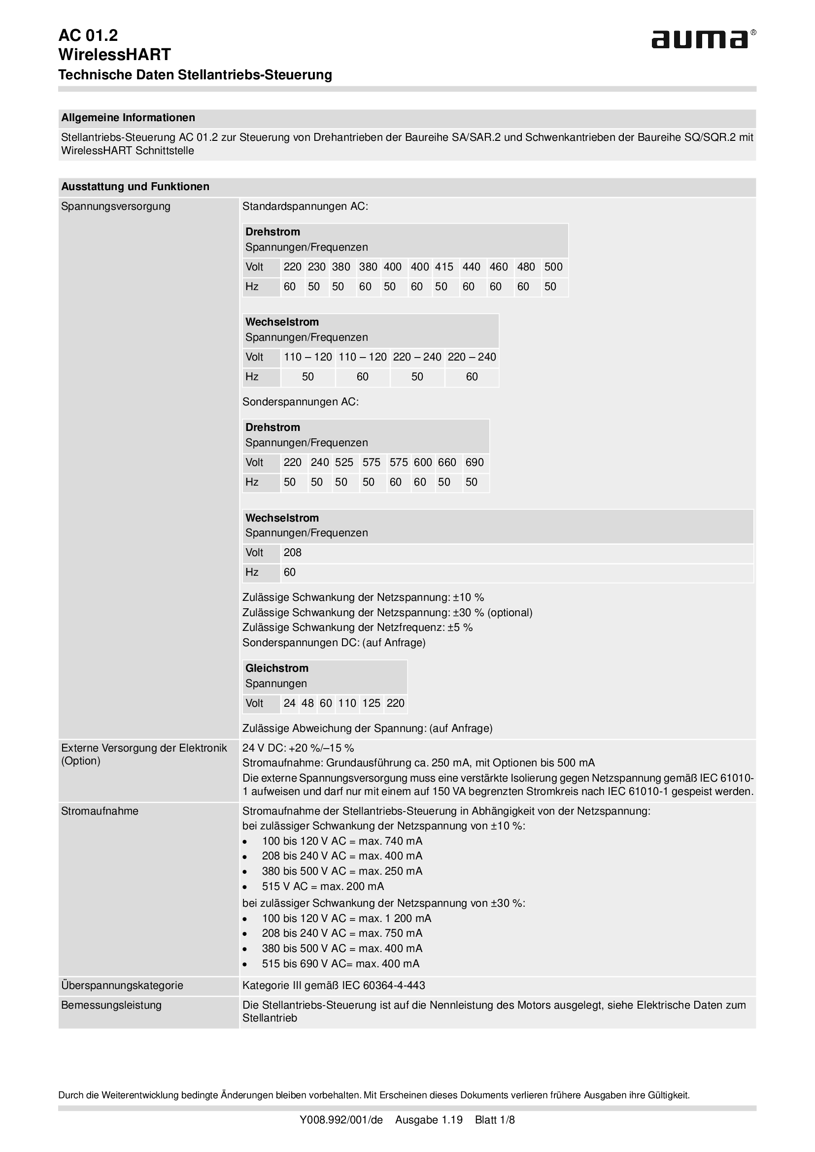
Stellantriebs-Steuerung AUMATIC AC 01.2, WirelessHART
Technical data
Technical description
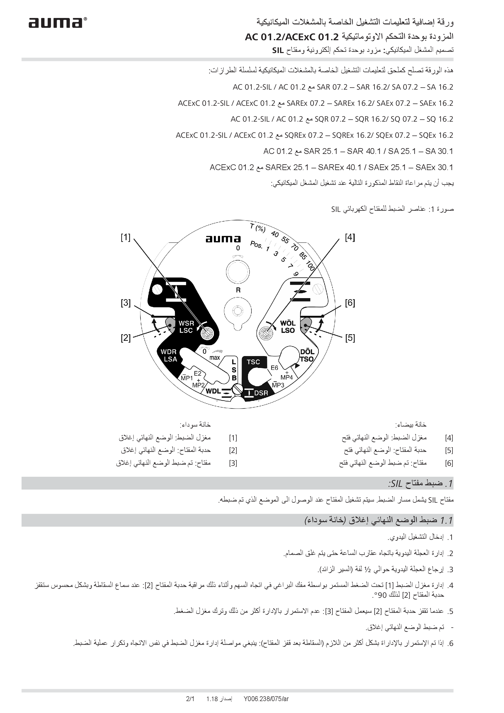
Supplement AUMATIC AC 01.2/ACExC 01.2, version actuators: with elektronic control unit (MWG) and SIL limit switching
Technical description
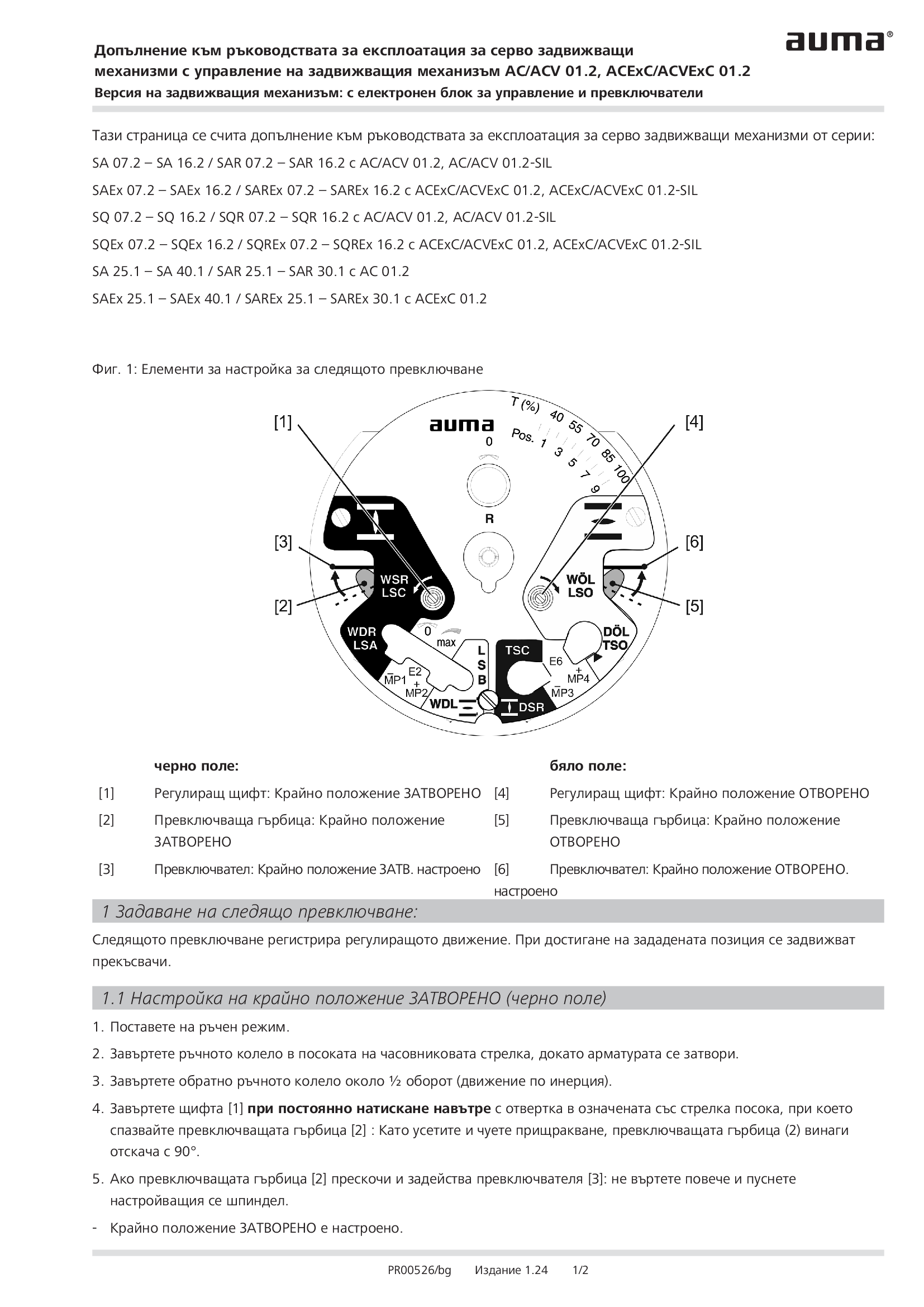
Supplement AUMATIC AC 01.2/ACExC 01.2, version actuators: with elektronic control unit (MWG) and limit switching
Technical description
Wiring diagram

A1: AUMATIC AC 01.2 position feedback signal 0/4 - 20 mA (potentiometer in actuator), basic version, reversing contactors OPEN, STOP, CLOSE, EMERGENCY (24 V DC), 6 programmable output contacts, AUMA power class A1 - A3
Wiring diagram

A1N: AUMATIC AC 01.2 position/torque feedback signal 0/4 - 20 mA (MWG in actuator), reversing contactors OPEN, STOP, CLOSE, EMERGENCY (24 V DC), 6 programmable output contacts, AUMA power class A1 - A3
Wiring diagram

A2: AUMATIC AC 01.2 positioner and postition feedback signal 0/4 - 20 mA (potentiometer in actuator), reversing contactors OPEN, STOP, CLOSE, EMERGENCY, MODE (24 V DC), 6 programmable output contacts, AUMA power class A1 - A3
Wiring diagram

A2DP: AUMATIC AC 01.2 position feedback (potentiometer in actuator), basic version, reversing contactors, Profibus, AUMA power class A1 - A3
Wiring diagram

A2ENIP: AUMATIC AC 01.2 position feedback (potentiometer in actuator), basic version, reversing contactors, Ethernet/IP, AUMA power class A3 - A3
Wiring diagram

A2FF: AUMATIC AC 01.2 position feedback (potentiometer in actuator), basic version, Reversing contactors, Foundation Fieldbus FF, AUMA power classes A1 – A3
Wiring diagram

A2HRT: AUMATIC AC 01.2 position feedback (potentiometer in actuator), basic version, Reversing contactors, HART actuatorAUMA power classes A1 – A3
Wiring diagram

A2HRTCO: AUMATIC AC 01.2 position feedback (potentiometer in actuator), basic version, Reversing contactors, HART Current Output, AUMA power classes A1 – A3
Wiring diagram

A2MB: AUMATIC AC 01.2 position feedback (potentiometer in actuator), basic version, reversing contactors, Modbus RTU, AUMA power class A1 - A3
Wiring diagram

A2MBTCP: AUMATIC AC 01.2 position feedback (potentiometer in actuator), basic version, Reversing contactors, Modbus TCP/IP, AUMA power classes A1 – A3
Wiring diagram

A2MBTCP: AUMATIC AC 01.2 position/torque feedback (MWG in actuator), Reversing contactors, Modbus TCP/IP, AUMA power classes A1 – A3
Wiring diagram

A2N: AUMATIC AC 01.2 positioner and position/torque feedback signal 0/4 - 20 mA (MWG in actuator), , reversing contactors OPEN, STOP, CLOSE, EMERGENCY, MODE (24 V DC), 6 programmable output contacts, AUMA power class A1 - A3
Wiring diagram

A2NDP: AUMATIC AC 01.2 position/torque feedback (MWG in actuator), reversing contactors, Profibus, AUMA power class A1 - A3
Wiring diagram

A2NENIP: AUMATIC AC 01.2, position/torque feedback (MWG in actuator, reversing contactors, Ethernet/IP, AUMA power class A1 - A 3
Wiring diagram

A2NFF: AUMATIC AC 01.2 position/torque feedback (MWG in actuator), Reversing contactors, Foundation Fieldbus FF, AUMA power classes A1 – A3
Wiring diagram

A2NHRT: AUMATIC AC 01.2 position/torque feedback (MWG in actuator), Reversing contactors, HART actuator, AUMA power classes A1 – A3
Wiring diagram

A2NHRTCO: AUMATIC AC 01.2 position/torque feedback (MWG in actuator), Reversing contactors, HART Current Output, AUMA power classes A1 – A3
Wiring diagram

A2NMB: AUMATIC AC 01.2 position/torque feedback (MWG in actuator), reversing contactors, Modbus RTU, AUMA power class A1 - A3
Wiring diagram

A3: AUMATIC AC 01.2 positioner and position feedback signal 0/4 - 20 mA (potentiometer in actuator), thyristors OPEN, STOP, CLOSE, EMERGENCY, MODE (24 V DC), 6 programmable output contacts, AUMA power class B1/B2
Wiring diagram

A3: AUMATIC AC 01.2 positioner and position feedback signal 0/4 - 20 mA (potentiometer in actuator), thyristors OPEN, STOP, CLOSE, EMERGENCY, MODE (24 V DC), 6 programmable output contacts, AUMA power class B3
Wiring diagram

A3DP: AUMATIC AC 01.2 position feedback (potentiometer in actuator), thyristors, Profibus, AUMA power class B1/B2
Wiring diagram

A3DP: AUMATIC AC 01.2 position feedback (potentiometer in actuator), thyristors, Profibus, AUMA power class B2
Wiring diagram

A3ENIP: AUATIC AC 01.2 postition feedback (potentiometer in actuator), Thyristors, EtherNet/IP, AUMA power class B1/B2
Wiring diagram

A3ENIP: AUATIC AC 01.2 postition feedback (potentiometer in actuator), Thyristors, EtherNet/IP, AUMA power class B3
Wiring diagram

A3FF: AUMATIC AC 01.2 position feedback (potentiometer in actuator), Thyristors, Foundation Fieldbus FF, AUMA power class B1/B2
Wiring diagram

A3FF: AUMATIC AC 01.2 position feedback (potentiometer in actuator), Thyristors, Foundation Fieldbus FF, AUMA power class B3
Wiring diagram

A3HRT: AUMATIC AC 01.2 position feedback (potentiometer in actuator), Thyristors, HART actuator, AUMA power class B1/B2
Wiring diagram

A3HRT: AUMATIC AC 01.2 position feedback (potentiometer in actuator), Thyristors, HART actuator, AUMA power class B3
Wiring diagram

A3HRTCO: AUMATIC AC 01.2 position feedback (potentiometer in actuator), Thyristors, HART Current Output, AUMA power class B1/B2
Wiring diagram

A3HRTCO: AUMATIC AC 01.2 position feedback (potentiometer in actuator), Thyristors, HART Current Output, AUMA power class B3
Wiring diagram

A3MB: AUMATIC AC 01.2 position feedback (potentiometer in actuator), thyristors, Modbus, AUMA power class B1/B2
Wiring diagram

A3MB: AUMATIC AC 01.2 position feedback (potentiometer in actuator), thyristors, Modbus, AUMA power class B3
Wiring diagram

A3MBTCP: AUMATIC AC 01.2 position feedback (potentiometer in actuator), Thyristors, Modbus TCP/IP, AUMA power class B1/B2
Wiring diagram

A3MBTCP: AUMATIC AC 01.2 position feedback (potentiometer in actuator), Thyristors, Modbus TCP/IP, AUMA power class B3
Wiring diagram

A3N: AUMATIC AC 01.2 positioner and position/torque feedback signal 0/4 - 20 mA (MWG in actuator), thyristors OPEN, STOP, CLOSE, EMERGENCY, MODE (24 V DC), 6 programmable output contacts, AUMA power class B1/B2
Wiring diagram

A3N: AUMATIC AC 01.2 positioner and position/torque feedback signal 0/4 - 20 mA (MWG in actuator), thyristors OPEN, STOP, CLOSE, EMERGENCY, MODE (24 V DC), 6 programmable output contacts, AUMA power class B3
Wiring diagram

A3NDP: AUMATIC AC 01.2 position/torque feedback (MWG in actuator), thyristors, Profibus, AUMA power class B1/B2
Wiring diagram

A3NDP: AUMATIC AC 01.2 position/torque feedback (MWG in actuator), thyristors, Profibus, AUMA power class B3
Wiring diagram

A3NENIP: AUMATIC AC 01.2 position/torque feedback (MWG in actuator), Thyristors, Ethernet/IP, AUMA power class B1/B2
Wiring diagram

A3NENIP: AUMATIC AC 01.2 position/torque feedback (MWG in actuator), Thyristors, Ethernet/IP, AUMA power class B3
Wiring diagram

A3NFF: AUMATIC AC 01.2 position/torque feedback (MWG in actuator), Thyristors, Foundation Fieldbus FF, AUMA power class B1/B2
Wiring diagram

A3NFF: AUMATIC AC 01.2 position/torque feedback (MWG in actuator), Thyristors, Foundation Fieldbus FF, AUMA power class B3
Wiring diagram

A3NHRT: AUMATIC AC 01.2 position/torque feedback (MWG in actuator), Thyristors, HART actuator, AUMA power class B1/B2
Wiring diagram

A3NHRT: AUMATIC AC 01.2 position/torque feedback (MWG in actuator), Thyristors, HART actuator, AUMA power class B3
Wiring diagram

A3NHRTCO: AUMATIC AC 01.2 position/torque feedback (MWG in actuator), Thyristors, HART actuator, AUMA power class B1/B2
Wiring diagram

A3NHRTCO: AUMATIC AC 01.2 position/torque feedback (MWG in actuator), Thyristors, HART actuator, AUMA power class B3
Wiring diagram

A3NMB: AUMATIC AC 01.2 position/torque feedback (MWG in actuator), thyristors, Modbus RTU, AUMA power class B1/B2
Wiring diagram

A3NMB: AUMATIC AC 01.2 position/torque feedback (MWG in actuator), thyristors, Modbus RTU, AUMA power class B3
Wiring diagram

A3NMBTCP: AUMATIC AC 01.2 position/torque feedback (MWG in actuator), Thyristors, Modbus TCP/IP, AUMA power class B1/B2
Wiring diagram

A3NMBTCP: AUMATIC AC 01.2 position/torque feedback (MWG in actuator), Thyristors, Modbus TCP/IP, AUMA power class B3
Wiring diagram

A3NPN: AUMATIC AC 01.2, position/torque feedback (MWG in actuator), Thyristors, Profinet, AUMA power class B1/B2
Wiring diagram

A3NPN: AUMATIC AC 01.2, position/torque feedback (MWG in actuator), Thyristors, Profinet, AUMA power class B3
Wiring diagram

A3PN: AUMATIC AC 01.2 position feedback (potentiometer in actuator), Thyristors, Profinet, AUMA power class B1/B2
Wiring diagram

A3PN: AUMATIC AC 01.2 position feedback (potentiometer in actuator), Thyristors, Profinet, AUMA power class B3
Wiring diagram

A4DP: AUMATIC AC 01.2 positioner and position feedback signal 0/4 - 20 mA (potentiometer in actuator),basic version, reversing contactors MODE, CLOSE, OPEN, STOP, EMERGENCY, I/O (24 V DC), Profibus DP, AUMA power class A1 - A3
Wiring diagram

A4ENIP: AUMATIC AC 01.2 positioner and position feedback signal 0/4 - 20 mA (potentiometer in actuator), basic version, reversing contactors MODE, CLOSE, OPEN, STOP, EMERGENCY, I/O (24 V DC), 6 programmable output contacts Ethernet/IP, AUMA power class
Wiring diagram

A4FF: AUMATIC AC 01.2 positioner and position feedback signal 0/4 – 20 mA (potentiometer in actuator), basic version, Reversing contactors MODE, CLOSE, OPEN, STOP, EMERGENCY, I/O (24V DC), 6 programmable output contacts, FF, AUMA power classes A1-A3
Wiring diagram

A4HRT: AUMATIC AC 01.2 positioner and position feedback signal 0/4-20mA (potentiometer in actuator), basic version, Reversing contactors MODE, CLOSE, OPEN, STOP, EMERGENCY, I/O (24V DC), 6 programmable output contacts, HART, AUMA power classes A1 – A3
Wiring diagram

A4HRT: AUMATIC AC 01.2 positioner and position feedback signal 0/4-20mA (potentiometer within actuator), basic version, Reversing contactors MODE, CLOSE, OPEN, STOP, EMERGENCY, I/O (24V DC), 6 programmable output contacts, HART AUMA power classes A1 – A3
Wiring diagram

A4HRTCO: AUMATIC AC 01.2 positioner and position feedback signal 0/4-20mA (potentiometer in actuator), basic version, Reversing contactors MODE, CLOSE, OPEN, STOP, EMERGENCY, I/O (24V DC), 6 programmable output contacts, HART, AUMA power classes A1-A3
Wiring diagram

A4MB: AUMATIC AC 01.2 positioner and position feedback signal 0/4 - 20 mA (potentiometer in actuator), basic version, reversing contactors MODE, CLOSE, OPEN, STOP, EMERGENCY, I/O (24 V DC), 6programmable output contacts, Modbus RTU, power class A1 - A3
Wiring diagram

A4N: AUMATIC AC 01.2 process controller and position/torque feedback signal 0/4 - 20 mA (MWG in actuator), thyristors CLOSE, OPEN, STOP, EMERGENCY, MODE (24 V DC), 6 programmable output contacts, AUMA power class B1/B2
Wiring diagram

A4NDP: AUMATIC AC 01.2 positioner and position/torque feedback signal 0/4 - 20 mA (MWG in actuator), reversing contactors MODE, CLOSE, OPEN, STOP, EMERGENCY, I/O (24 V DC), 6 programmable output contacts, Profibus DP, AUMA power class A1 - A3
Wiring diagram

A4NENIP: AUMATIC AC 01.2 positioner and position/torque feedbacksignal 0/4 - 20 mA (MWG in actuator), reversing contactors MODE, CLOSE, OPEN, STOP, EMERGENCY, I/O (24 v DC), 6 programmable output contacts, EtherNet/IP, AUMA power class A1 - A3
Wiring diagram

A4NHRT: AUMATIC AC 01.2 positioner and position/torque feedback signal 0/4 – 20 mA (MWG in actuator), Reversing contactors MODE, CLOSE, OPEN, STOP, EMERGENCY, I/O (24 V DC), 6 programmable output contacts, HART, AUMA power classes A1 – A3
Wiring diagram

A4NHRTCO: AUMATIC AC 01.2 position/torque feedback (MWG in actuator), Reversing contactors MODE, CLOSE, OPEN, STOP, EMERGENCY, I/O (24 V DC), 6 programmable output contacts, HART current output, AUMA power classes A1 – A3
Wiring diagram

A4NMB: AUMATIC AC 01.2 positioner and position/torque feedback signal 0/4 - 20 mA (MWG in actuator), reversing contactors MODE, CLOSE, OPEN, STOP, EMERGENCY, I/O (24 V DC), 6 programmable output contacts, Modbus RTU, AUMA power class A1 - A3
Wiring diagram

A4NMBTCP: AUMATIC AC 01.2 positioner and position/torque feedback signal 0/4 – 20 mA (MWG in actuator), Reversing contactors MODE, CLOSE, OPEN, STOP, EMERGENCY, I/O (24 V DC), 6 programmable output contacts, Modbus RTU, AUMA power classes A1 – A3
Wiring diagram

A5DP: AUMATIC AC 01.2 positioner and position feedback signal 0/4 - 20 mA (potentiometer in actuator), thyristors MODE, CLOSE, OPEN, STOP, EMERGENCY, I/O (24 V DC), 6 programmable output contacts, Profibus DP, AUMA power class B1/B2
Wiring diagram

A5DP: AUMATIC AC 01.2 positioner and position feedback signal 0/4 - 20 mA (potentiometer in actuator), thyristors MODE, CLOSE, OPEN, STOP, EMERGENCY, I/O (24 V DC), 6 programmable output contacts, Profibus DP, AUMA power class B3
Wiring diagram

A5ENIP: AUMATIC AC 01.2 positioner and position feedback signal 0/4 - 20 mA (potentiometer in actuator), Thyristors, MODE, CLOSE, OPEN, STOP, EMERGENCY, I/O (24 V DC), 6 programmable output contacts, EtherNet/IP, AUMA power class B1 / B2
Wiring diagram

A5ENIP: AUMATIC AC 01.2 positioner and position feedback signal 0/4 - 20 mA (potentiometer in actuator), Thyristors, MODE, CLOSE, OPEN, STOP, EMERGENCY, I/O (24 V DC), 6 programmable output contacts, EtherNet/IP, AUMA power class B3
Wiring diagram

A5FF: AUMATIC AC 01.2 positioner and position feedback signal 0/4 – 20 mA (potentiometer in actuator), Thyristors MODE, CLOSE, OPEN, STOP, EMERGENCY, I/O (24 V DC), 6 programmable output contacts, Foundation Fieldbus, AUMA power class B1/B2
Wiring diagram

A5FF: AUMATIC AC 01.2 positioner and position feedback signal 0/4 – 20 mA (potentiometer in actuator), Thyristors MODE, CLOSE, OPEN, STOP, EMERGENCY, I/O (24 V DC), 6 programmable output contacts, Foundation Fieldbus, AUMA power class B3
Wiring diagram

A5FF: AUMATIC AC 01.2 positioner and position feedback signal 0/4 – 20 mA (potentiometer in actuator), Thyristors MODE, CLOSE, OPEN, STOP, EMERGENCY, I/O (24 V DC), 6 programmable output contacts,´Foundation Fieldbus, AUMA power class B1/B2
Wiring diagram

A5HRT: AUMATIC AC 01.2 positioner and position feedback signal 0/4 – 20 mA (potentiometer in actuator), Thyristors MODE, CLOSE, OPEN, STOP, EMERGENCY, I/O (24 V DC), 6 programmable output contacts, HART, AUMA power class B1/B2
Wiring diagram

A5HRT: AUMATIC AC 01.2 positioner and position feedback signal 0/4 – 20 mA (potentiometer in actuator), Thyristors MODE, CLOSE, OPEN, STOP, EMERGENCY, I/O (24 V DC), 6 programmable output contacts, HART, AUMA power class B3
Wiring diagram

A5HRTCO: AUMATIC AC 01.2 position feedback (potentiometer in actuator), Thyristors MODE, CLOSE, OPEN, STOP, EMERGENCY, I/O (24 V DC), 6 programmable output contacts, HART Current Output, AUMA power class B1/B2
Wiring diagram

A5HRTCO: AUMATIC AC 01.2 position feedback (potentiometer in actuator), Thyristors MODE, CLOSE, OPEN, STOP, EMERGENCY, I/O (24 V DC), 6 programmable output contacts, HART Current Output, AUMA power class B3
Wiring diagram

A5MB: AUMATIC AC 01.2 positioner and position feedback signal 0/4 - 20 mA (potentiometer in actuator), thyristors MODE, CLOSE, OPEN, STOP, EMERGENCY, I/O (24 V DC), 6 prgrammable output contacts, Modbus RTU, AUMA power class B1/B2
Wiring diagram

A5MB: AUMATIC AC 01.2 positioner and position feedback signal 0/4 - 20 mA (potentiometer in actuator), thyristors MODE, CLOSE, OPEN, STOP, EMERGENCY, I/O (24 V DC), 6 prgrammable output contacts, Modbus RTU, AUMA power class B3
Wiring diagram

A5MBTCP: AUMATIC AC 01.2 positioner and position feedback signal 0/4 – 20 mA (potentiometer in actuator), Thyristors MODE, CLOSE, OPEN, STOP, EMERGENCY, I/O (24 V DC), 6 programmable output contacts, Modbus TCP/IP, AUMA power class B1/B2
Wiring diagram

A5MBTCP: AUMATIC AC 01.2 positioner and position feedback signal 0/4 – 20 mA (potentiometer in actuator), Thyristors MODE, CLOSE, OPEN, STOP, EMERGENCY, I/O (24 V DC), 6 programmable output contacts, Modbus TCP/IP, AUMA power class B3
Wiring diagram

A5N: AUMATIC AC 01.2 position/torque feedback signal 0/4 - 20 mA (MWG in actuator), reversing contactors CLOSE, OPEN, STOP, EMERGENCY, INTERLOCK CLOSE, INTERLOCK OPEN, 6 programmable output contacts, AUMA power class A1 - A3
Wiring diagram

A5NDP: AUMATIC AC 01.2 positioner and position/torque feedback signal 0/4 - 20 mA (MWG in actuator), thyristors MODE, CLOSE, OPEN, STOP, EMERGENCY, I/O (24 V DC), 6 programmable output contacts, Profibus DP, AUMA power class B1/B2
Wiring diagram

A5NDP: AUMATIC AC 01.2 positioner and position/torque feedback signal 0/4 - 20 mA (MWG in actuator), thyristors MODE, CLOSE, OPEN, STOP, EMERGENCY, I/O (24 V DC), 6 programmable output contacts, Profibus DP, AUMA power class B3
Wiring diagram

A5NENIP: AUMATIC AC 01.2 positioner and position/torque feedback signal 0/4 - 20 mA (WG in actuator), Thyristors MODE, CLOSE, OPEN, STOP, EMERGENCY, I/O (24 v DC), 6 programmable output contacts, EtherNet/IP, power class B1 / B2
Wiring diagram

A5NENIP: AUMATIC AC 01.2 positioner and position/torque feedback signal 0/4 - 20 mA (WG in actuator), Thyristors MODE, CLOSE, OPEN, STOP, EMERGENCY, I/O (24 v DC), 6 programmable output contacts, EtherNet/IP, power class B3
Wiring diagram

A5NFF: AUMATIC AC 01.2 positioner and position/torque feedback signal 0/4 – 20 mA (MWG in actuator), Thyristors MODE, CLOSE, OPEN, STOP, EMERGENCY, I/O (24 V DC), 6 programmable output contacts, Foundation Fieldbus FF, AUMA power class B1/B2
Wiring diagram

A5NFF: AUMATIC AC 01.2 positioner and position/torque feedback signal 0/4 – 20 mA (MWG in actuator), Thyristors MODE, CLOSE, OPEN, STOP, EMERGENCY, I/O (24 V DC), 6 programmable output contacts, Foundation Fieldbus FF, AUMA power class B3
Wiring diagram

A5NHRT: AUMATIC AC 01.2 positioner and position/torque feedback signal 0/4 – 20 mA (MWG in actuator), Thyristors MODE, CLOSE, OPEN, STOP, EMERGENCY, I/O (24 V DC), 6 programmable output contacts, HART, AUMA power class B1/B2
Wiring diagram

A5NHRT: AUMATIC AC 01.2 positioner and position/torque feedback signal 0/4 – 20 mA (MWG in actuator), Thyristors MODE, CLOSE, OPEN, STOP, EMERGENCY, I/O (24 V DC), 6 programmable output contacts, HART, AUMA power class B3
Wiring diagram

A5NHRTCO: AUMATIC AC 01.2 position/torque feedback (MWG in actuator), Thyristors MODE, CLOSE, OPEN, STOP, EMERGENCY, I/O (24 V DC), 6 programmable output contacts, HART Current Output, AUMA power class B1/B2
Wiring diagram

A5NHRTCO: AUMATIC AC 01.2 position/torque feedback (MWG in actuator), Thyristors MODE, CLOSE, OPEN, STOP, EMERGENCY, I/O (24 V DC), 6 programmable output contacts, HART Current Output, AUMA power class B3
Wiring diagram

A5NMB: AUMATIC AC 01.2 positioner and position/torque feedback signal 0/4 - 20 mA (MWG in actuator) thyristors MODE, CLOSE, OPEN, EMERGENCY, I/O (24 V DC), 6 programmable output contacts, Modbus RTU, AUMA power class B1/B2
Wiring diagram

A5NMB: AUMATIC AC 01.2 positioner and position/torque feedback signal 0/4 - 20 mA (MWG in actuator) thyristors MODE, CLOSE, OPEN, EMERGENCY, I/O (24 V DC), 6 programmable output contacts, Modbus RTU, AUMA power class B3
Wiring diagram

A5NMBTCP: AUMATIC AC 01.2 positioner and position/torque feedback signal 0/4 – 20 mA (MWG in actuator), Thyristors MODE, CLOSE, OPEN, STOP, EMERGENCY, I/O (24 V DC), 6 programmable output contacts, Modbus TCP/IP, AUMA power class B1/B2
Wiring diagram

A5NMBTCP: AUMATIC AC 01.2 positioner and position/torque feedback signal 0/4 – 20 mA (MWG in actuator), Thyristors MODE, CLOSE, OPEN, STOP, EMERGENCY, I/O (24 V DC), 6 programmable output contacts, Modbus TCP/IP, AUMA power class B3
Wiring diagram

A5NPN: AUMATIC AC 01.2 positioner and position/torque feedback signal 0/4 – 20 mA (MWG in actuator), Thyristors, Profinet, AUMA power class B1/B2
Wiring diagram

A5NPN: AUMATIC AC 01.2 positioner and position/torque feedback signal 0/4 – 20 mA (MWG in actuator), Thyristors, Profinet, AUMA power class B3
Wiring diagram

A5PN: AUMATIC AC 01.2 positioner and position feedback signal 0/4 – 20 mA (potentiometer in actuator), Thyristors, Profinet, AUMA power class B1/B2
Wiring diagram

A5PN: AUMATIC AC 01.2 positioner and position feedback signal 0/4 – 20 mA (potentiometer in actuator), Thyristors, Profinet, AUMA power class B3
Wiring diagram

AV2HRT: AUMATIC AC 01.2 position feedback (potentiometer in actuator), basic version, HART actuator, 1-ph; 220 V - 240 V
Wiring diagram

AV2HRT: AUMATIC AC 01.2 position feedback (potentiometer in actuator), basic version, HART actuator, 3-ph; 380 V - 480 V
Wiring diagram

AV2NHRT: AUMATIC AC 01.2 position/torque feedback (MWG in actuator), HART actuator, 3-ph; 380 V - 480 V
Wiring diagram
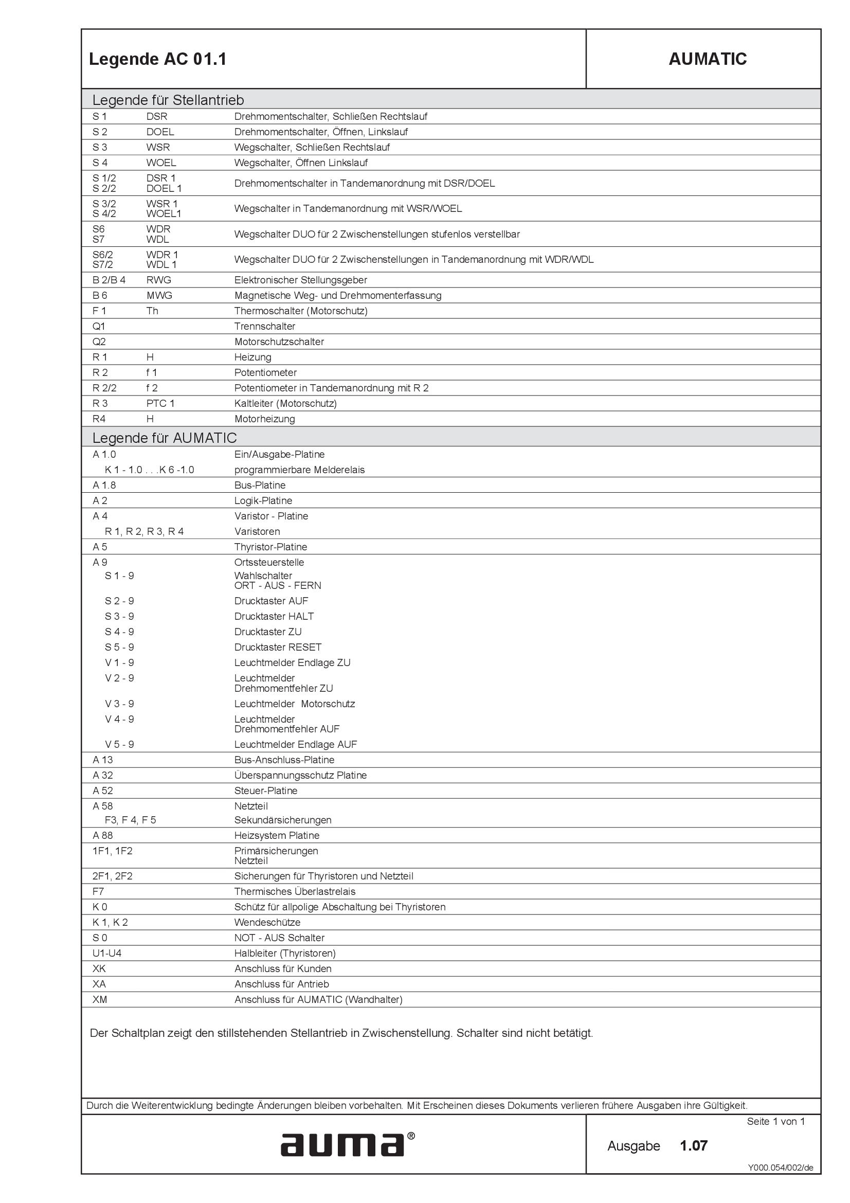
Legend AC 01.1
Wiring diagram
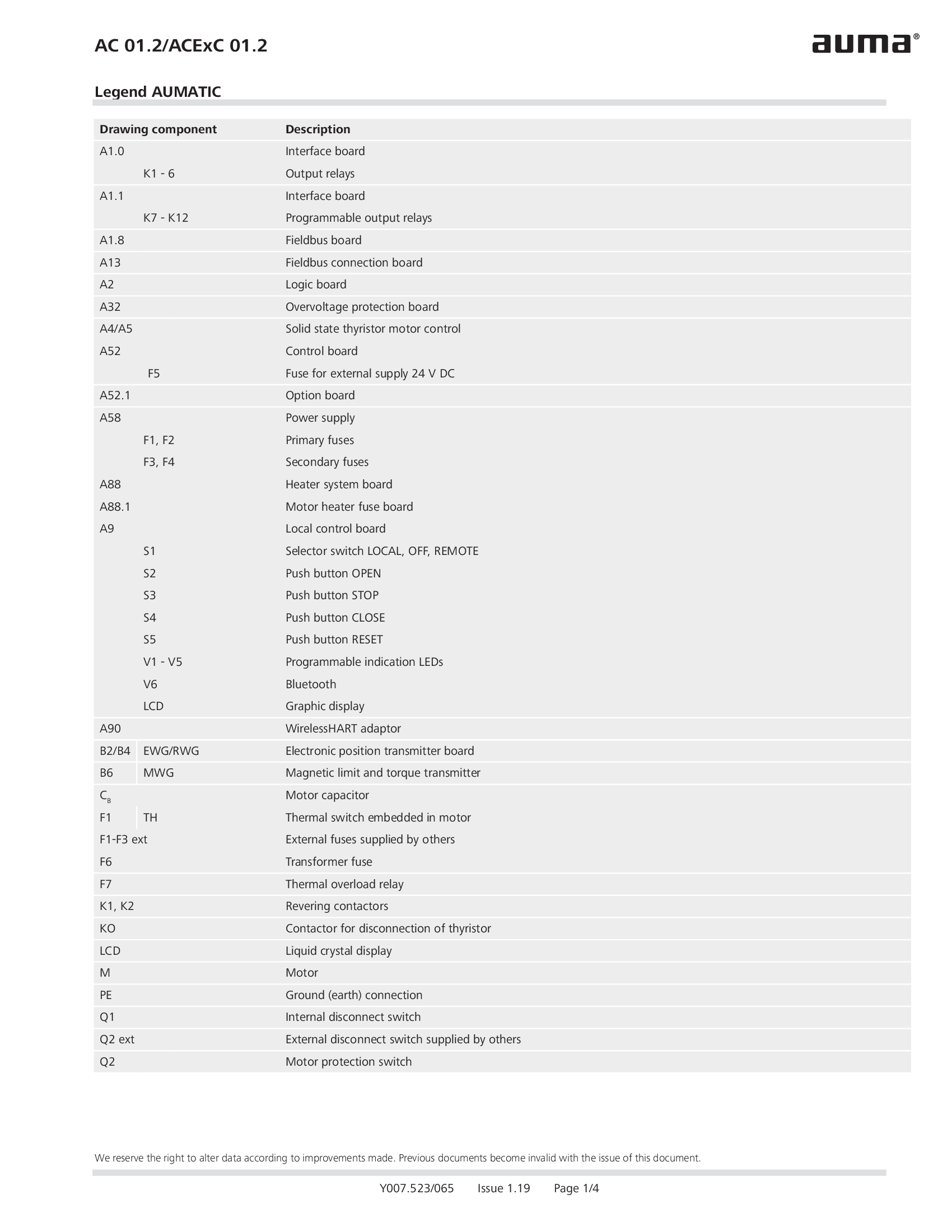
Legend AC 01.2/ACEx 01.2
Wiring diagram

Legend AC 01.2/ACEx 01.2, AC 01.2-SIL/ACExC 01.2-SIL
Wiring diagram
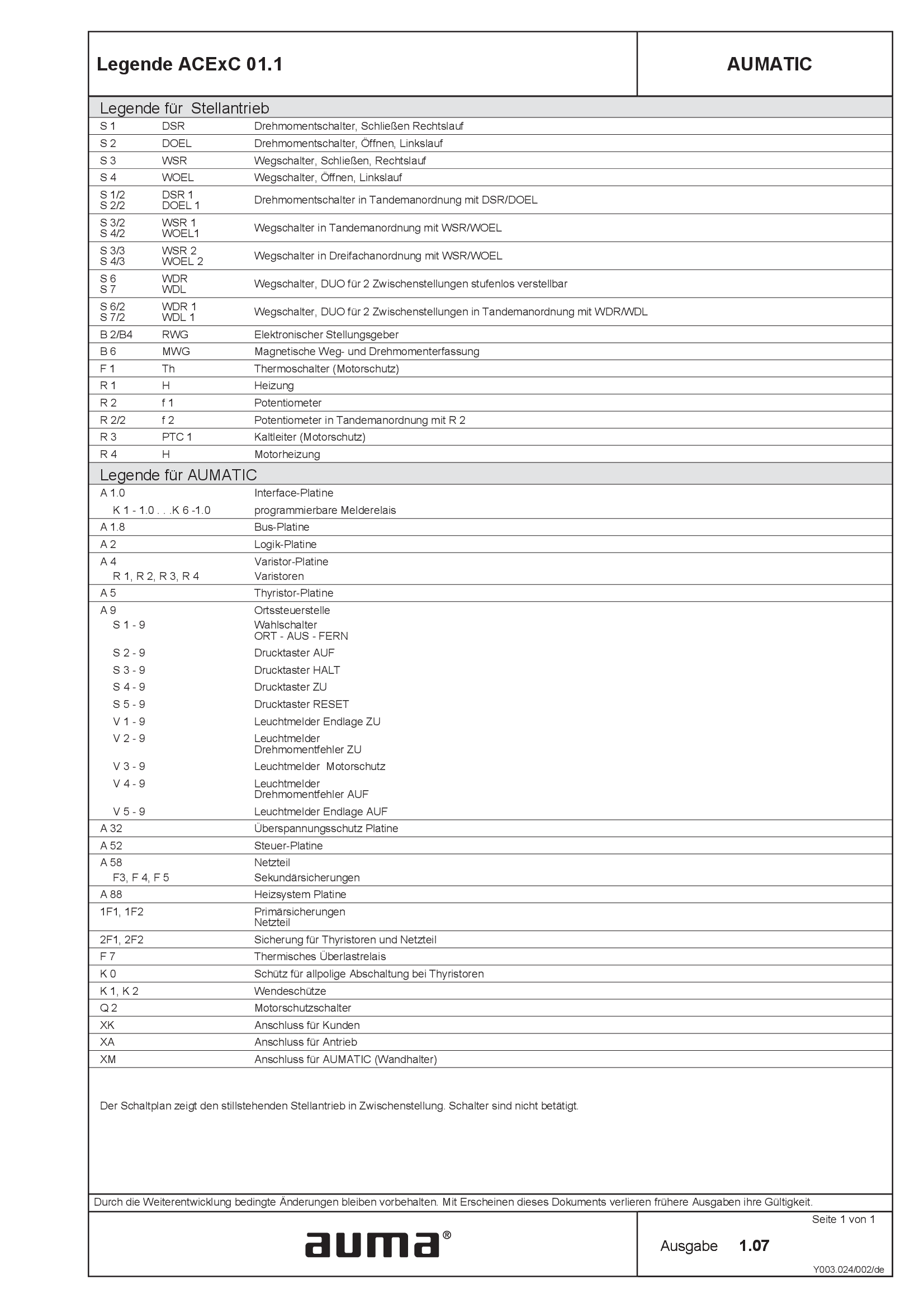
Legend ACExC01.1
Wiring diagram
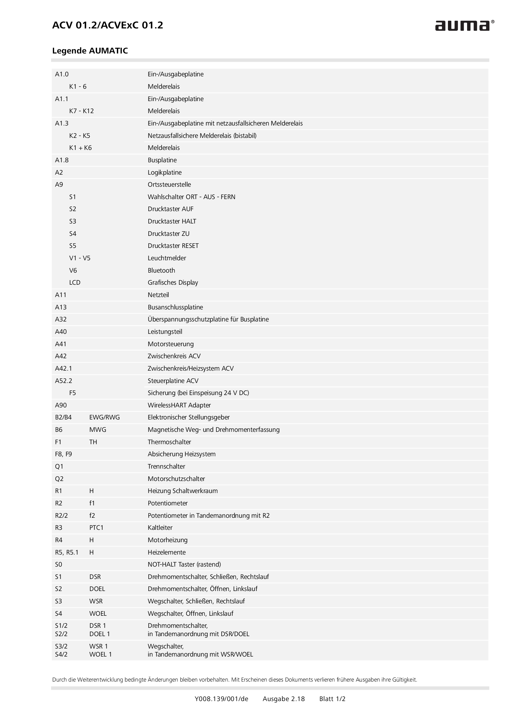
Legend ACV 01.2/ACVEx 01.2
Wiring diagram
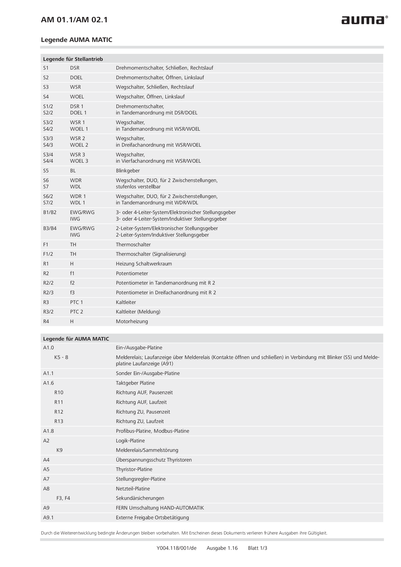
Legend AM 01.1/AM 02.1
Wiring diagram
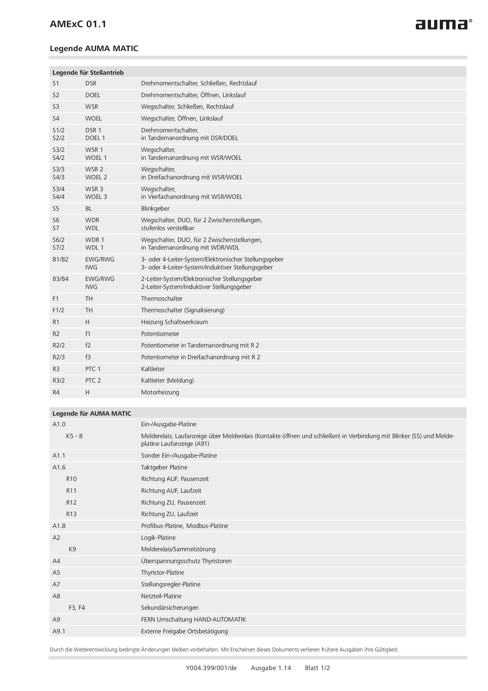
Legend AMExC 01.1
Wiring diagram

Legend SGC/SVC
Wiring diagram
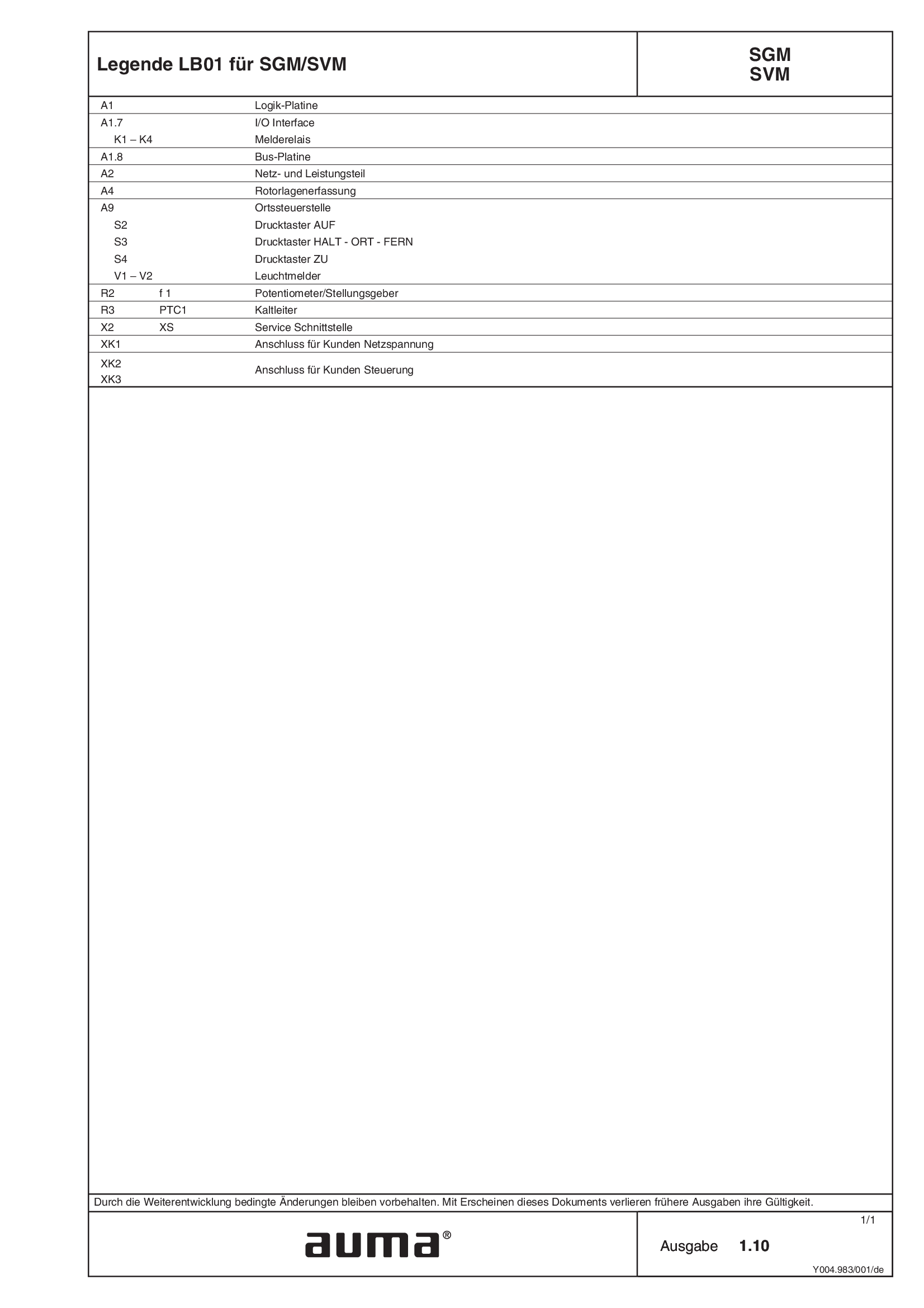
Legend SGM/SVM
Wiring diagram
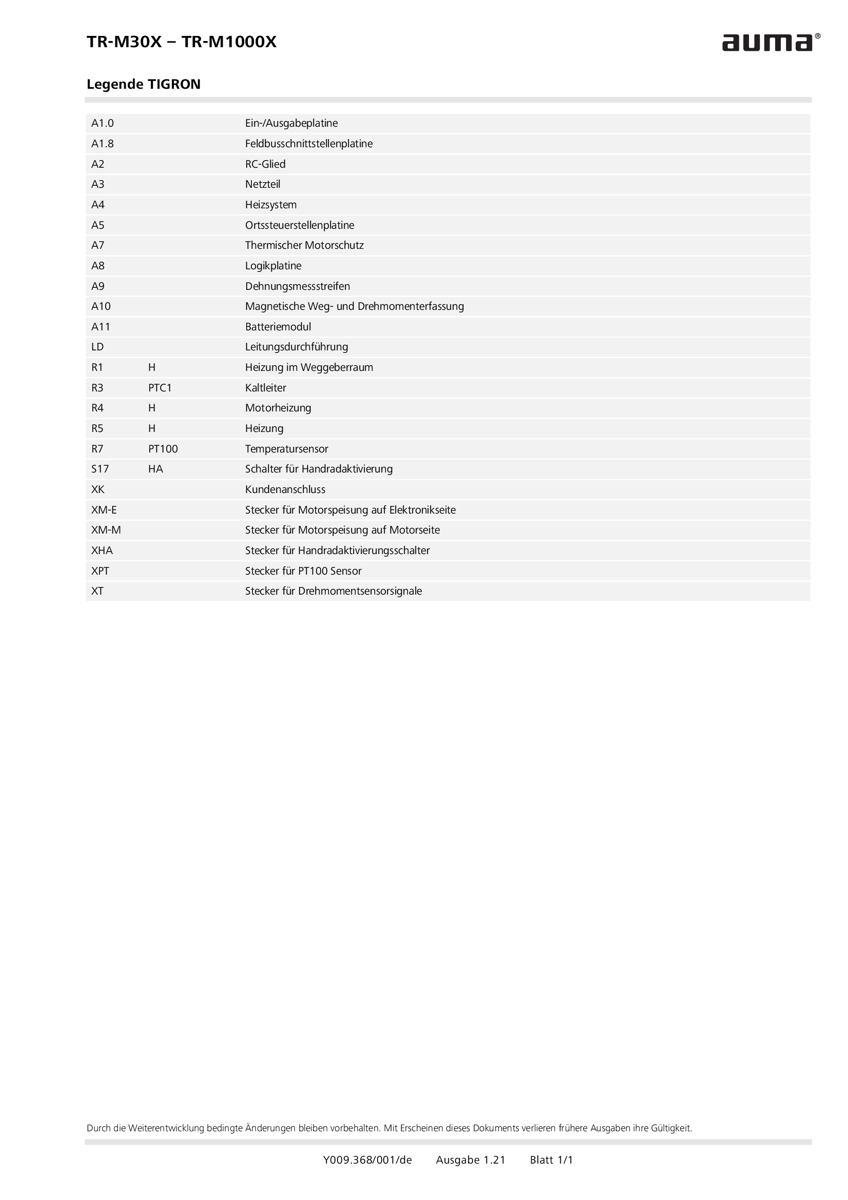
Legend TR-M30X – TR-M1000X
Wiring diagram
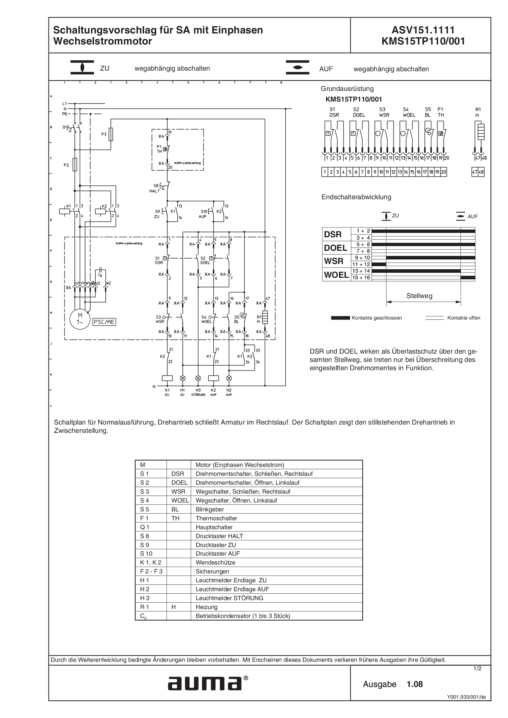
SA.1, 1-ph AC, ASV151.1111 /ASV151.1121 KMS15TP110/001
Wiring diagram
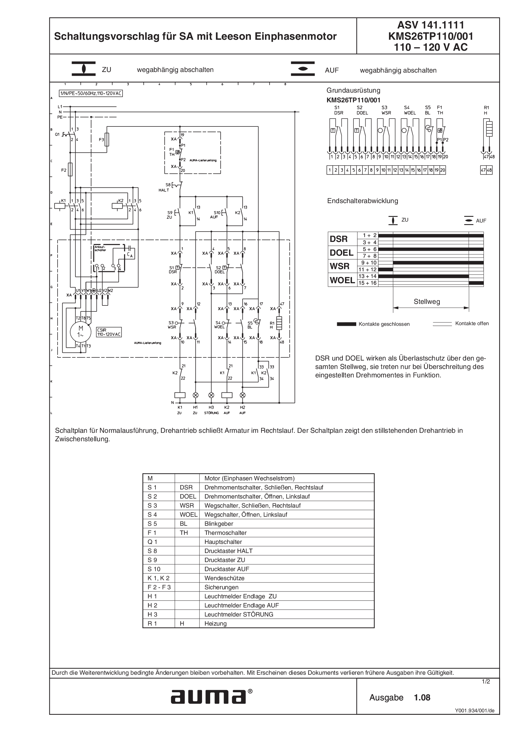
SA.1, 1-ph AC, Leeson motor ASV141.1111 /ASV141.1121 KMS26TP110/001 110 - 120 V AC
Wiring diagram
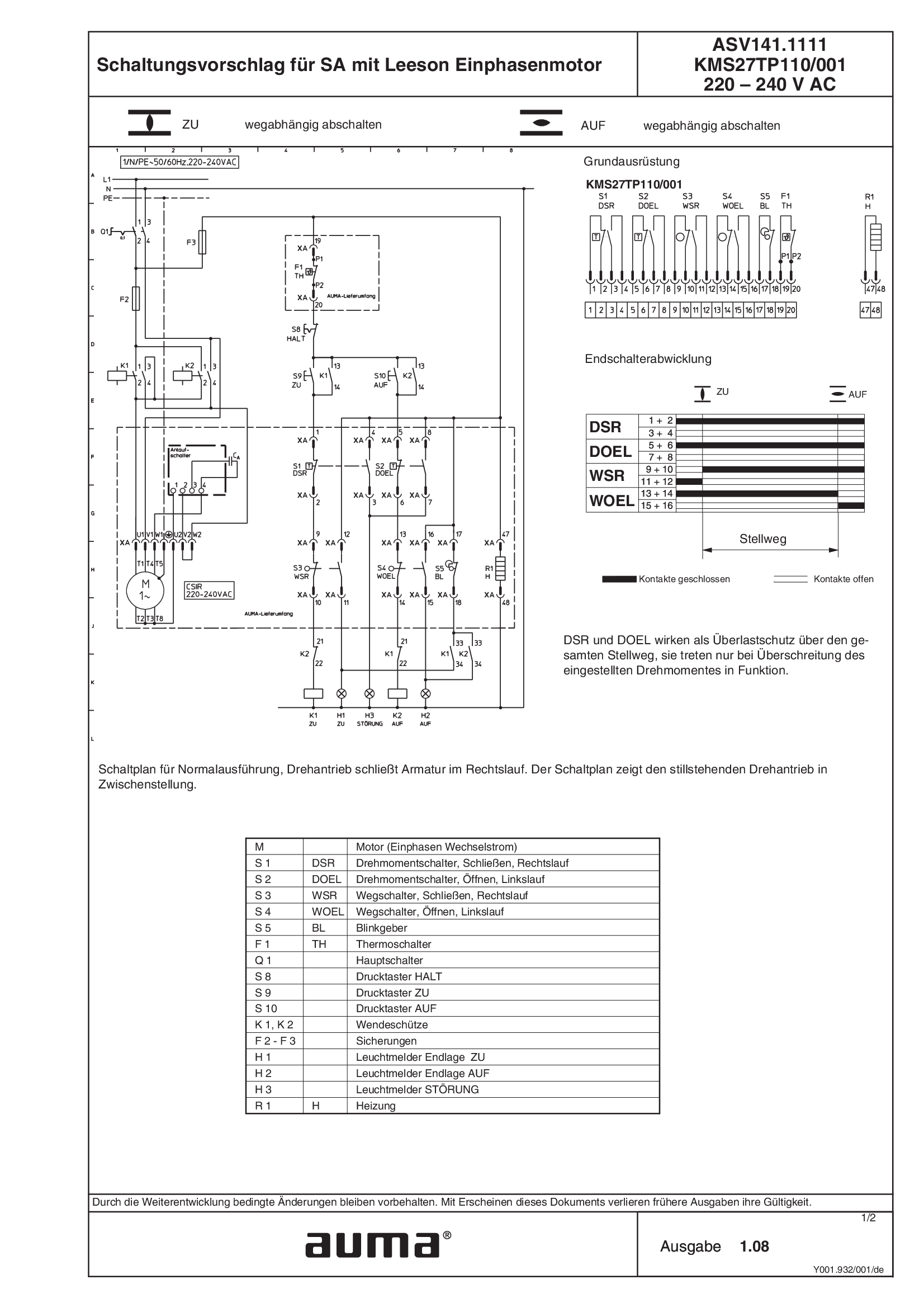
SA.1, 1-ph AC, Leeson motor ASV141.1111 /ASV141.1121 KMS27TP110/001 220 - 240 V AC
Wiring diagram
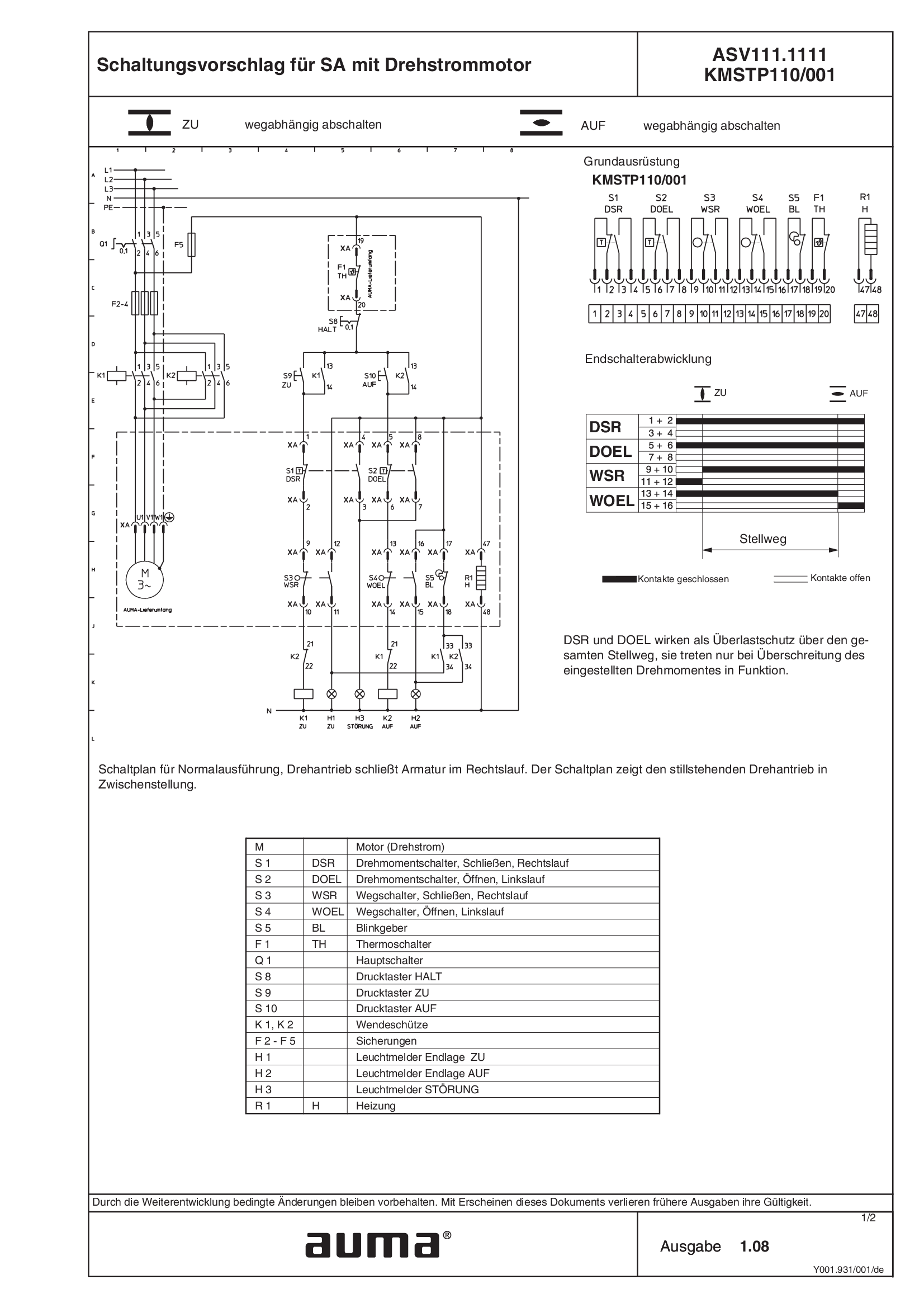
SA.1, 3-ph AC ASV111.1111 /ASV111.1121 KMSTP110/001
Wiring diagram
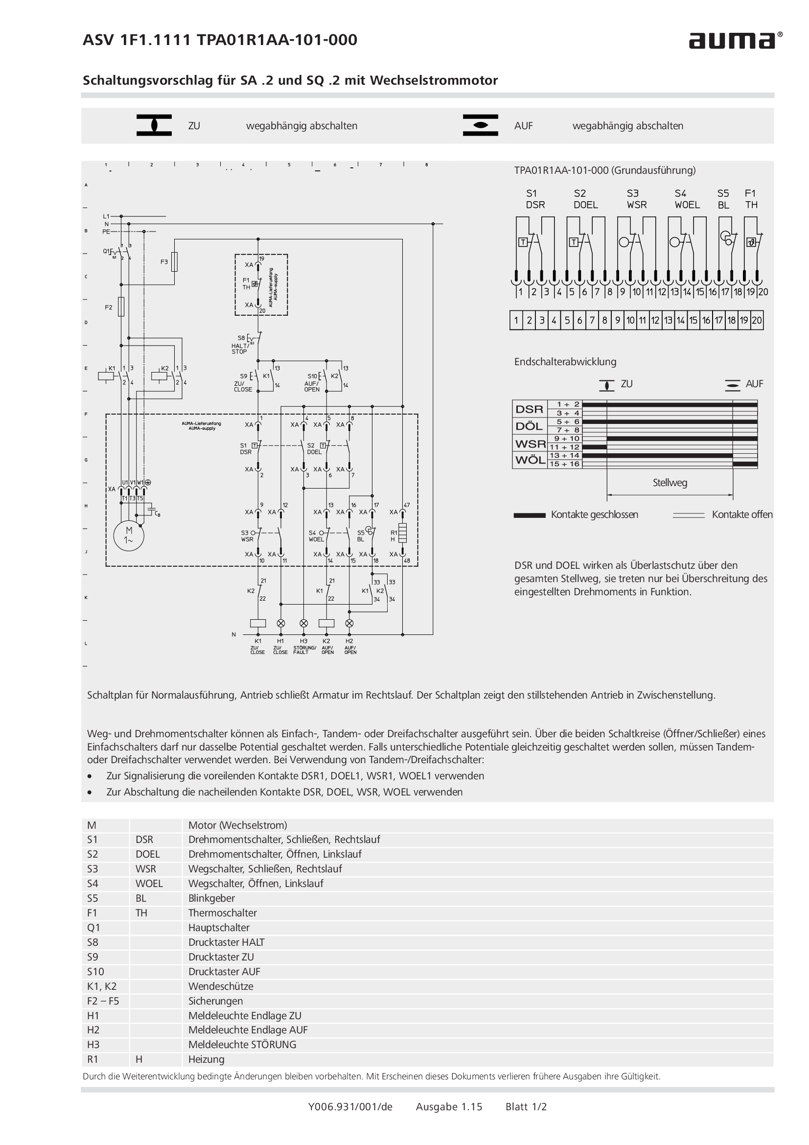
SA.2/SQ.2, 1-ph AC ASV1F1.1111 /ASV1F1.1121 TPA01R1AA-101-000
Wiring diagram
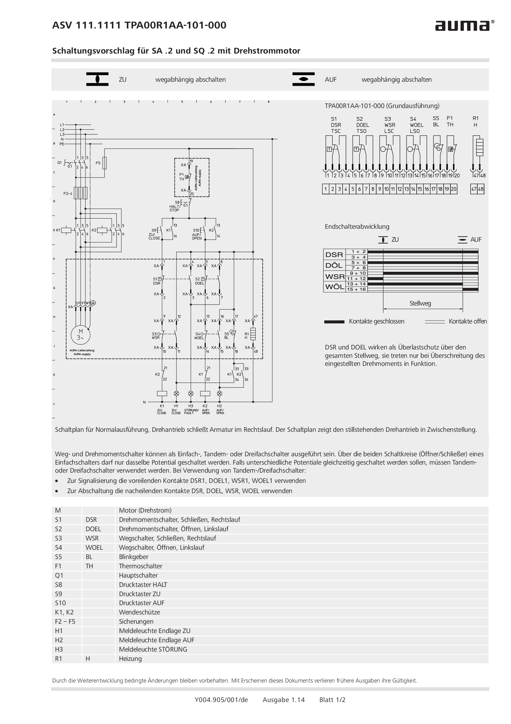
SA.2/SQ.2, 3-ph AC ASV111.1111 /ASV111.1121 TPA00R1AA-101-000
Wiring diagram
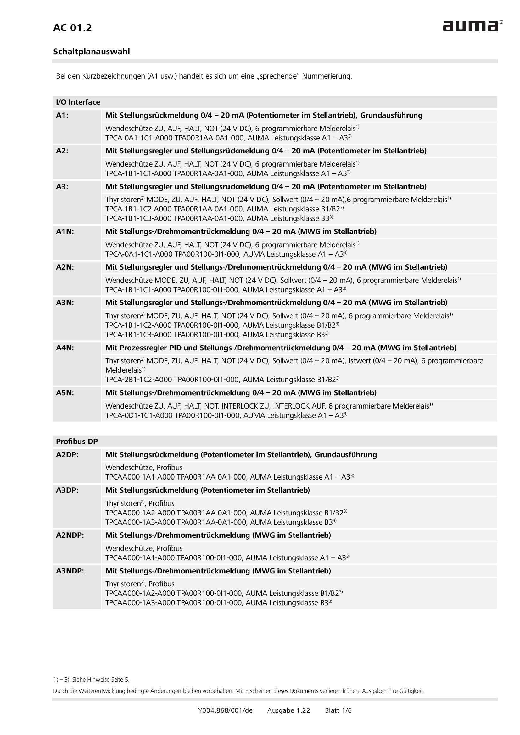
Selection for wiring diagram for AUMATIC AC 01.2
Wiring diagram
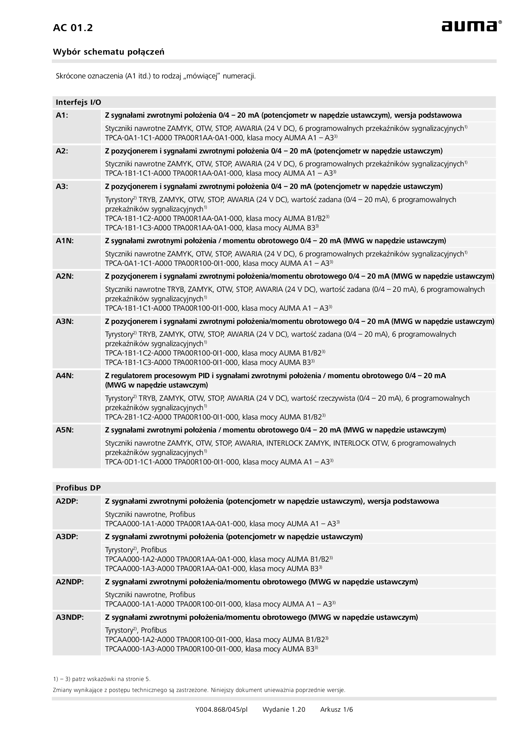
Selection for wiring diagram for AUMATIC AC 01.2/ACExC 01.2
Wiring diagram
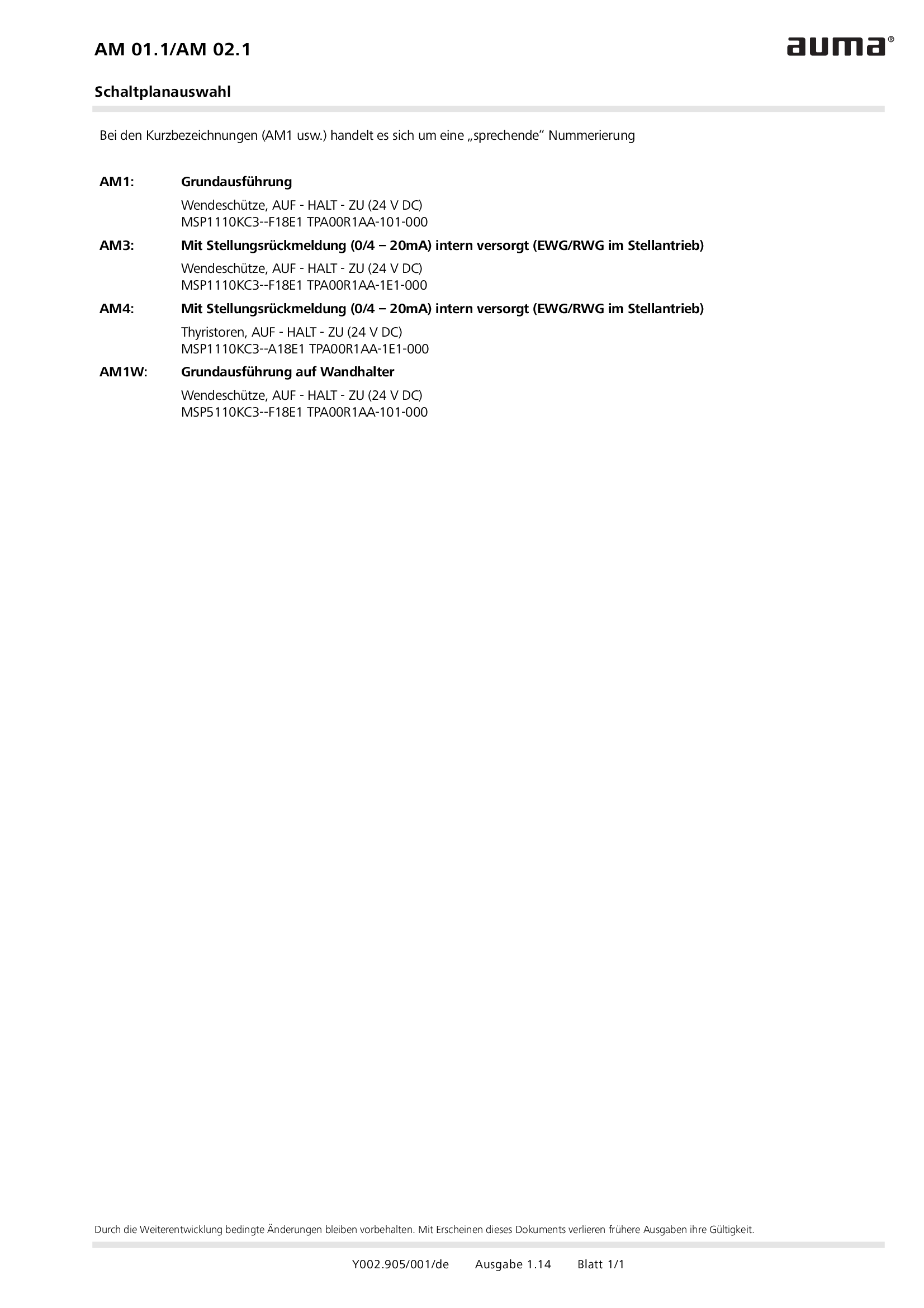
Selection of wiring diagrams for MATIC AM 01.1/AM 02. 1
Wiring diagram
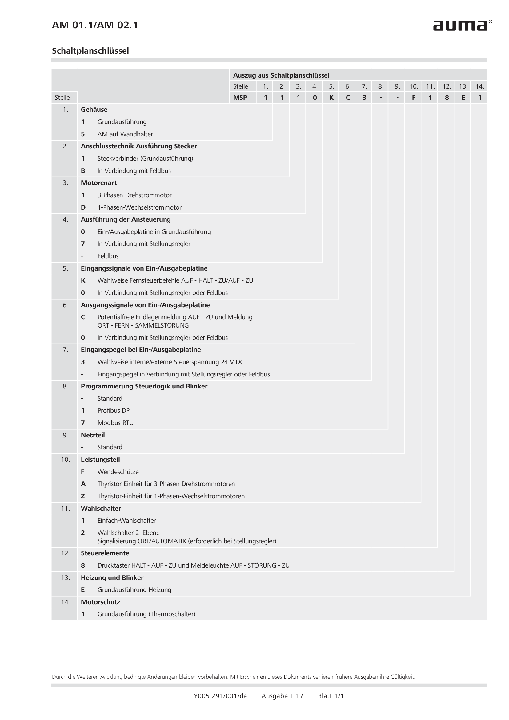
Wiring diagram code AM 01.1/AM 02.1
Wiring diagram
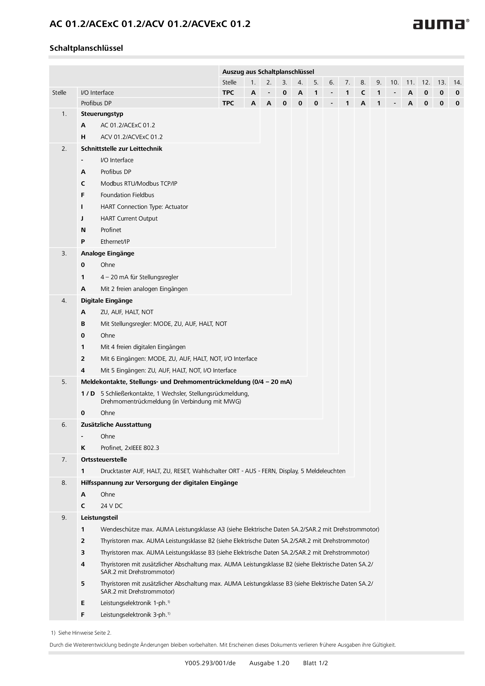
Wiring diagram code for AC 01.2/ACExC 01.2/ACV 01.2/ACVExC 01.2
Wiring diagram
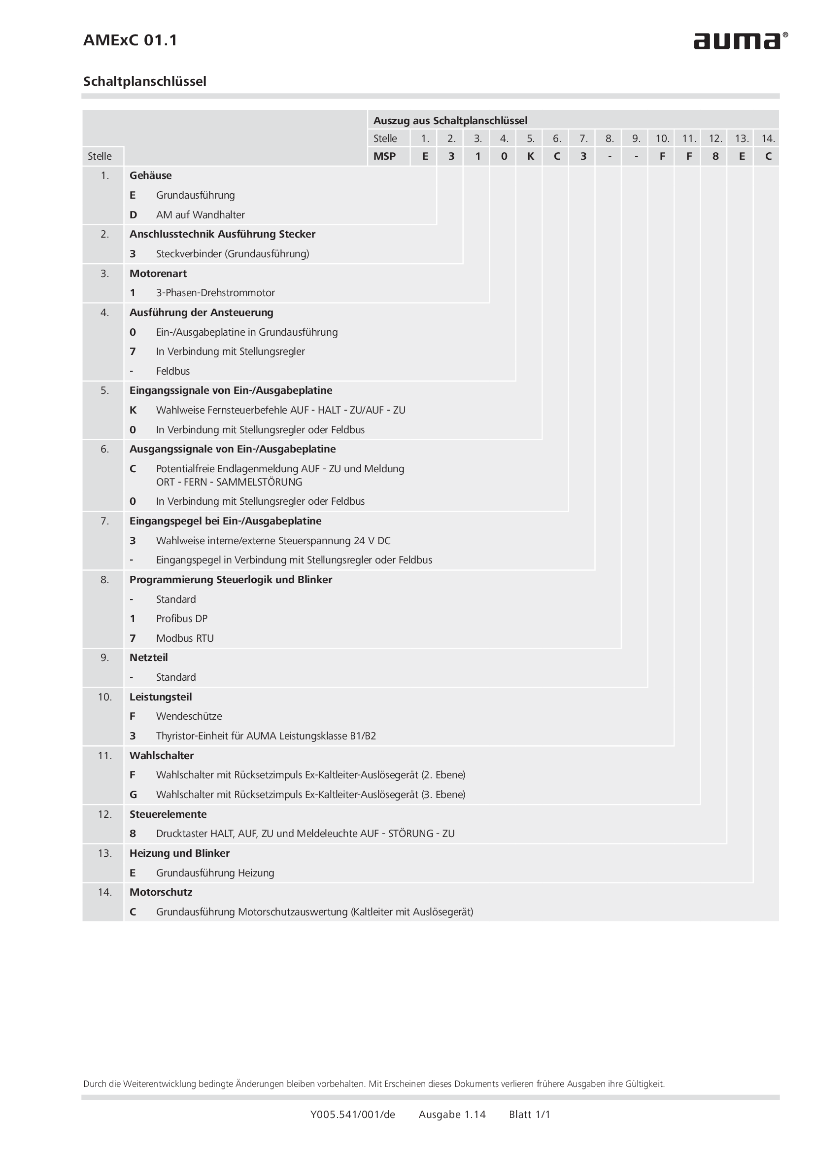
Wiring diagram code for AMExC 01.1
Wiring diagram


