Wyniki wyszukiwania dla
"Supplement Power tool emergency operation SA .2"
Spare parts list

Multi-turn actuators SAN 07.2 – 16.2/SARN 07.2 –16.2 for use in nuclear power plants
Spare parts list
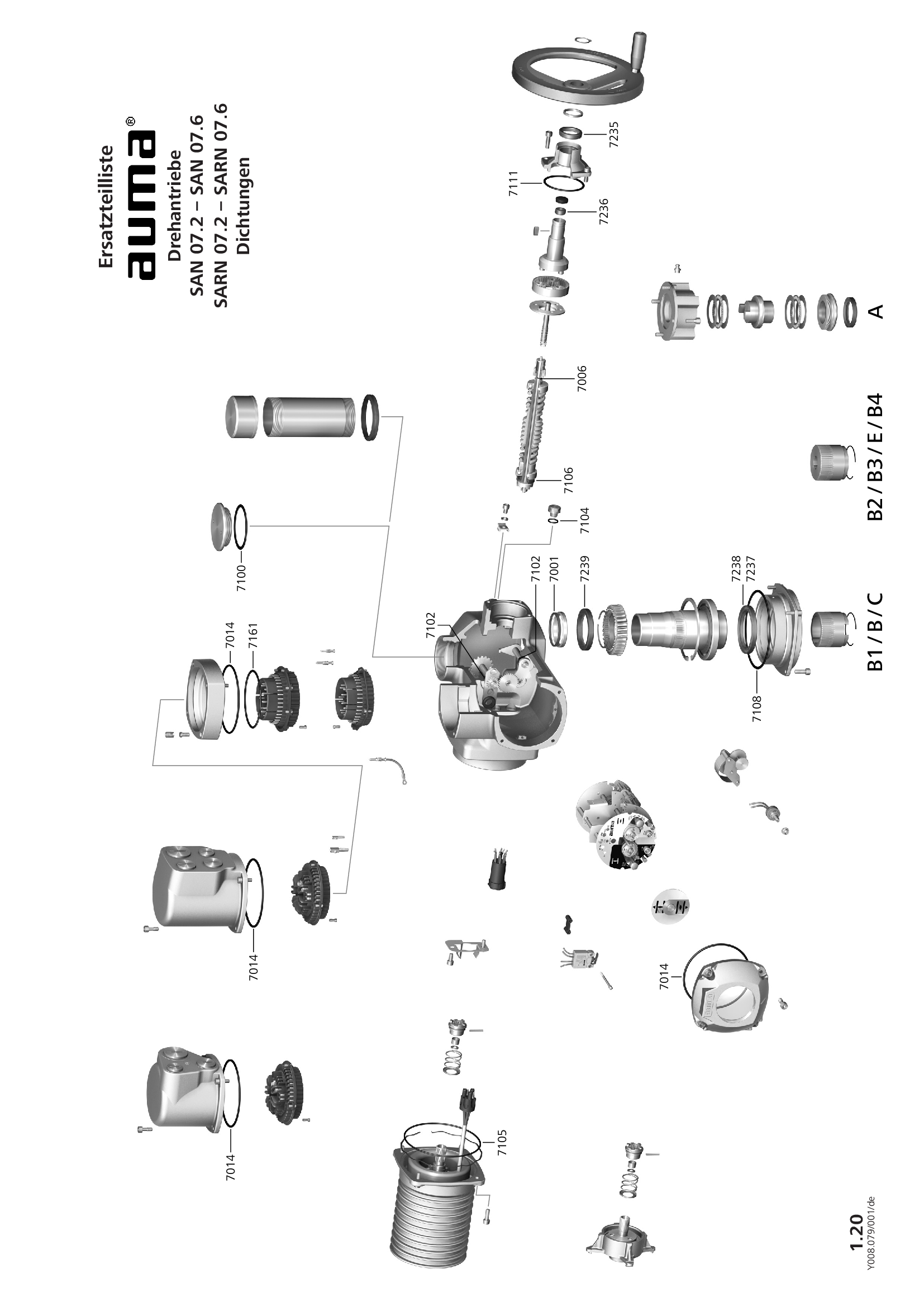
Multi-turn actuators SAN 07.2-07.6/SARN 07.2-07.6 for use in nuclear power plants, seals
Spare parts list
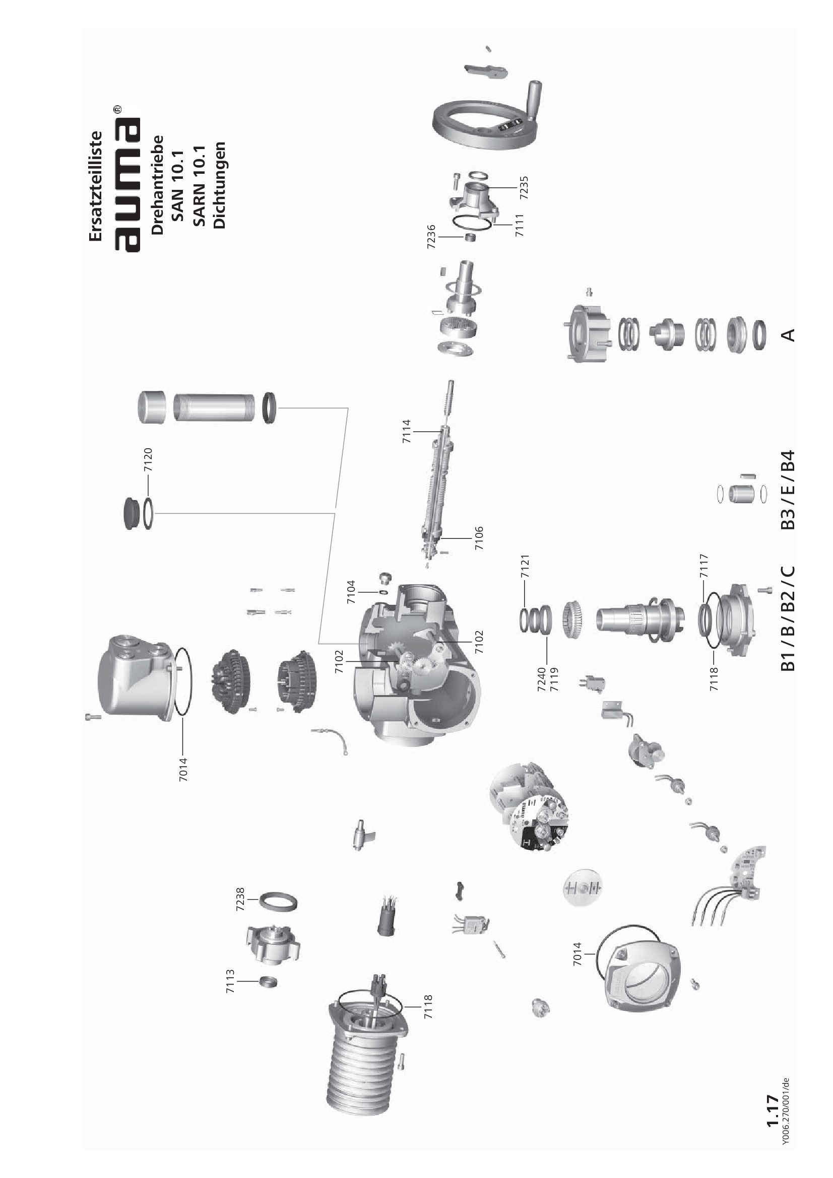
Multi-turn actuators SAN 10.1 for use in nuclear power plants, seals
Spare parts list

Multi-turn actuators SAN 10.2/SARN 10.2 for use in nuclear power plants, seals
Spare parts list

Multi-turn actuators SAN 14.1 - SAN 14.5 for use in nuclear power plants, seals
Spare parts list
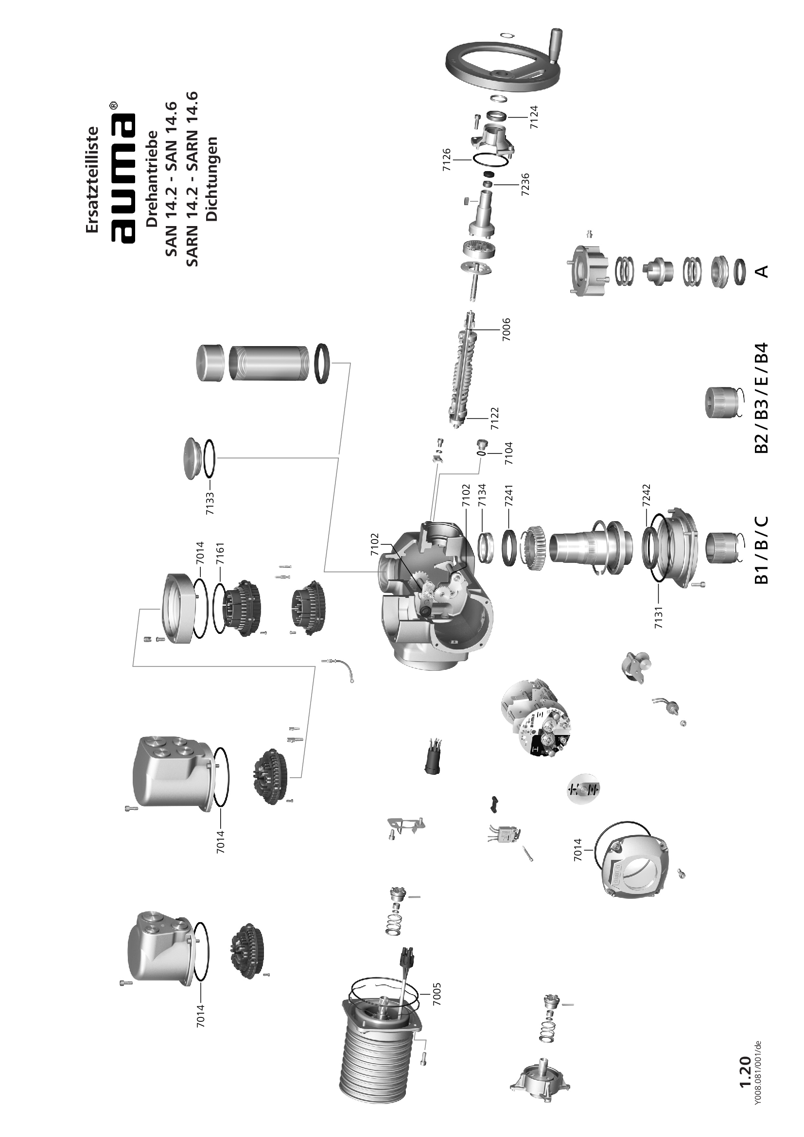
Multi-turn actuators SAN 14.2-14.6/SARN 14.2-14.6 for use in nuclear power plants, seals
Spare parts list
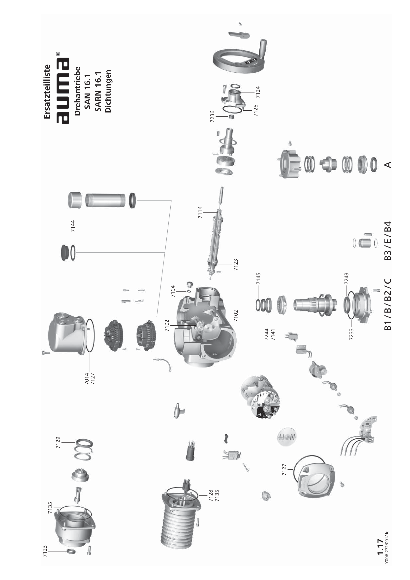
Multi-turn actuators SAN 16.1 for use in nuclear power plants, seals
Spare parts list

Multi-turn actuators SAN 16.2/SARN 16.2 for use in nuclear power plants, seals
Spare parts list

Multi-turn actuators SAN 25.1 – 35.1/SARN 25.1 – 30.1 for use in nuclear power plants
Spare parts list
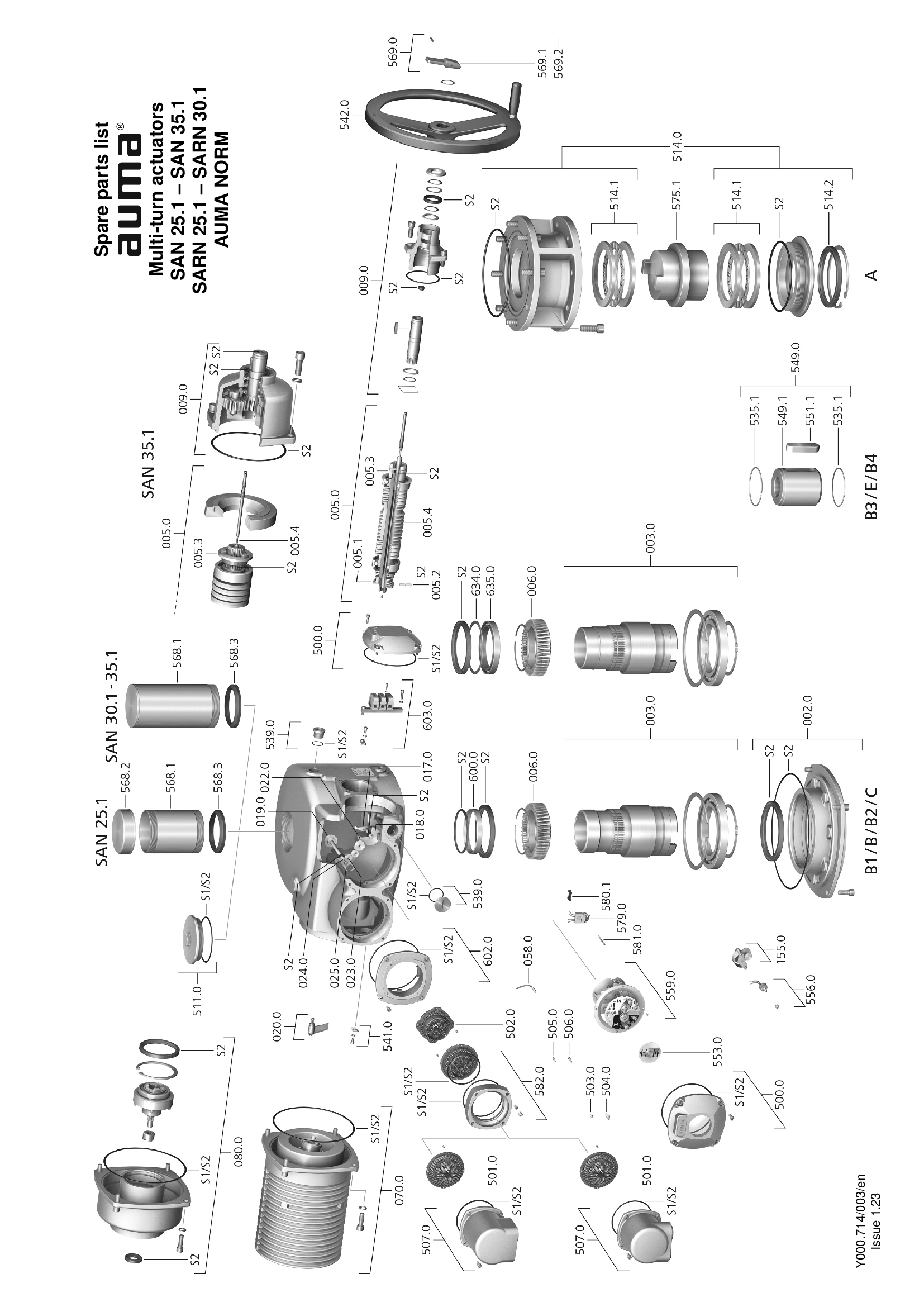
Multi-turn actuators SAN 25.1 – 35.1/SARN 25.1 – SARN 30.1 for use in nuclear power plants
Spare parts list

Multi-turn actuators SAN 25.1/SARN 25.1 IEEE 382-2006 for use in nuclear power plants, seals
Spare parts list
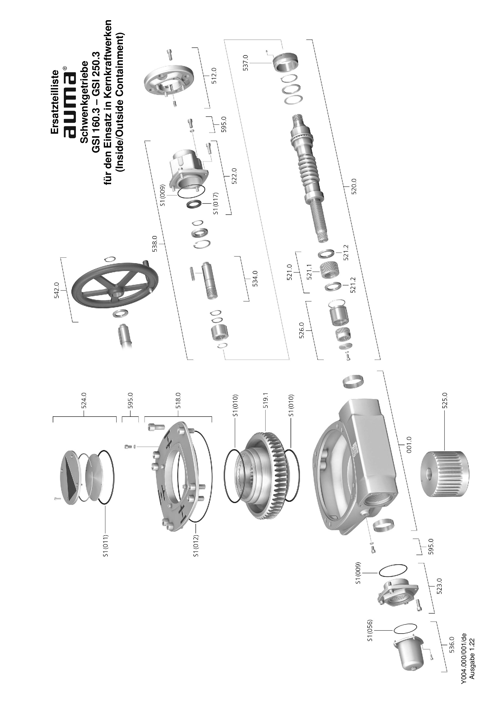
Part-turn gearboxes GSI 160. 3 – 250.3, nuclear power plants
Spare parts list

Part-turn gearboxes GSI 160.3 – 250.3, nuclear power plants
Spare parts list

Part-turn gearboxes GSI 63.3 – 125.3, nuclear power plants
Spare parts list
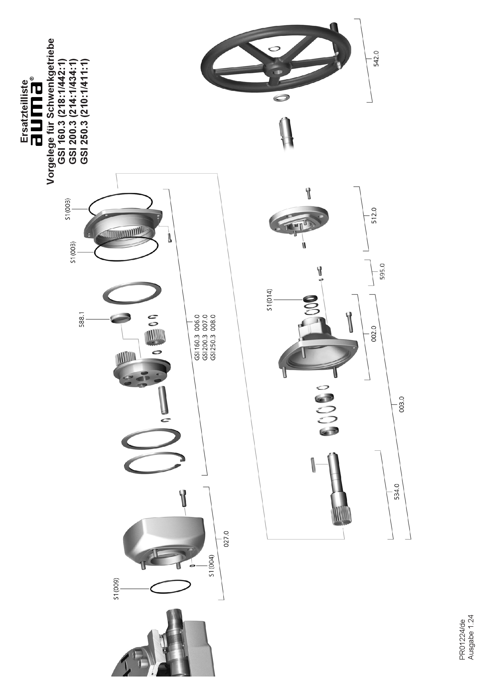
Primary reduction gearing GSI 160.3 – 250.3, 4:1/ 8:1, nuclear power plants
Spare parts list
Specification
Actuators SA/SAR 07.2 - 16.2, SQ/SQR 05.2 - 14.2, AC 01.2, Non-intrusiv
Specification
Pobierz
application/vnd.openxmlformats-officedocument.wordprocessingml.document
44.1 KB

Actuators SA/SAR 07.2 - 16.2, SQ/SQR 05.2 - 14.2, AC 01.2, Non-intrusiv, Foundation Fieldbus
Specification
Pobierz
application/vnd.openxmlformats-officedocument.wordprocessingml.document
50 KB

Actuators SA/SAR 07.2 - 16.2, SQ/SQR 05.2 - 14.2, AC 01.2, Non-intrusiv, Modbus RTU
Specification
Pobierz
application/vnd.openxmlformats-officedocument.wordprocessingml.document
50 KB

Actuators SA/SAR 07.2 - 16.2, SQ/SQR 05.2 - 14.2, AC 01.2, Non-intrusiv, Modbus RTU, Masterstation
Specification
Pobierz
application/vnd.openxmlformats-officedocument.wordprocessingml.document
50.6 KB

Actuators SA/SAR 07.2 - 16.2, SQ/SQR 05.2 - 14.2, AC 01.2, Non-intrusiv, Profibus DP
Specification
Pobierz
application/vnd.openxmlformats-officedocument.wordprocessingml.document
46.4 KB
Multi-turn actuators SA 07.2 - 16.2 actuator controls AUMA MATIC AM 01.1
Specification
Pobierz
application/vnd.openxmlformats-officedocument.wordprocessingml.document
43.7 KB
Technical data
Linear actuators/linear thrust units SA 07.2 - 16.2/LE 12.1 -200.1, open-close duty
Technical data
Linear actuators/linear thrust units SARN 07.1 - 16.1/LEN 12.1 -200.1, modulating duty, nuclear power plants
Technical data
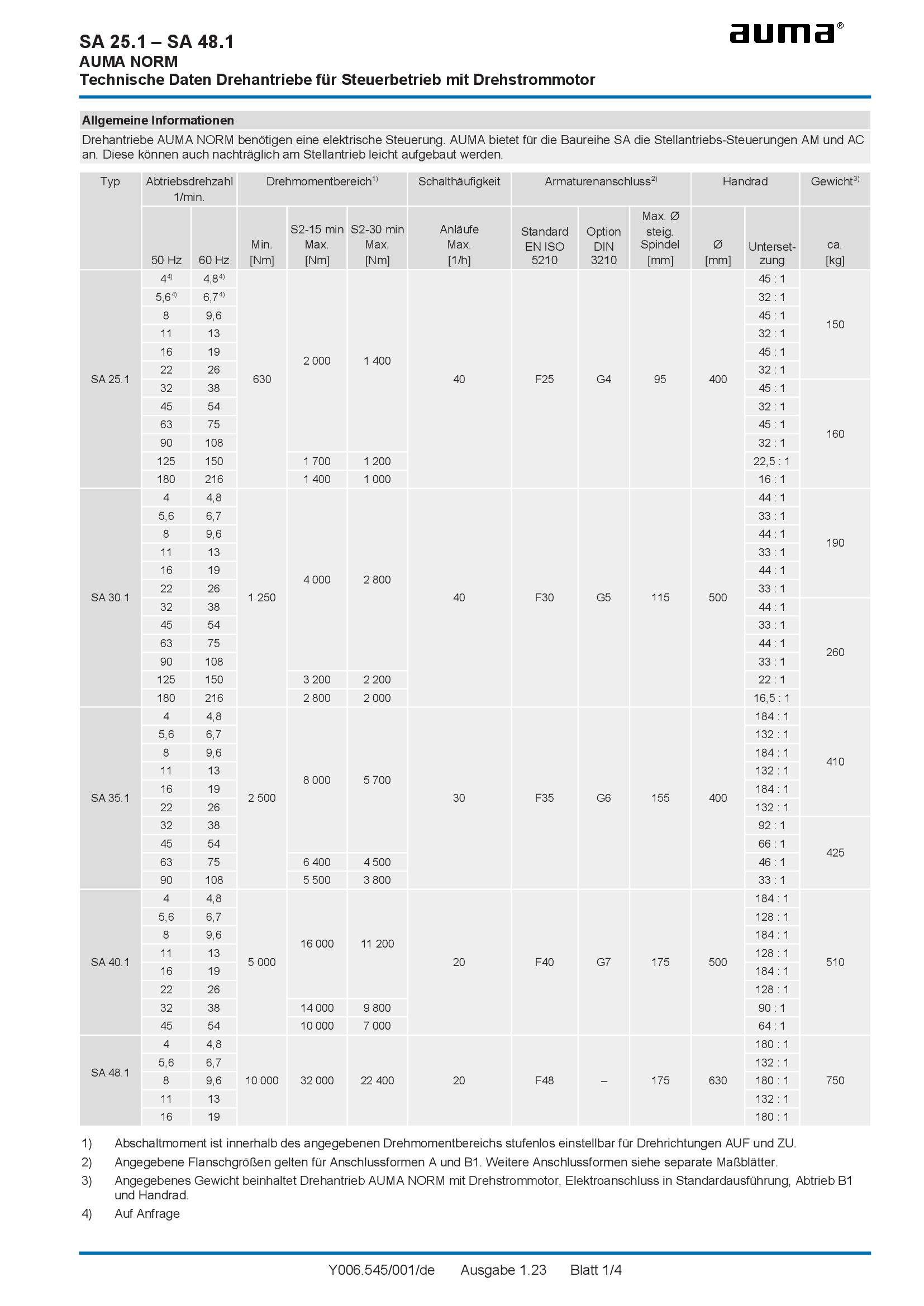
Multi-turn actuators SA 07.1 - 48.1, open-close duty, 3-phase AC
Technical data
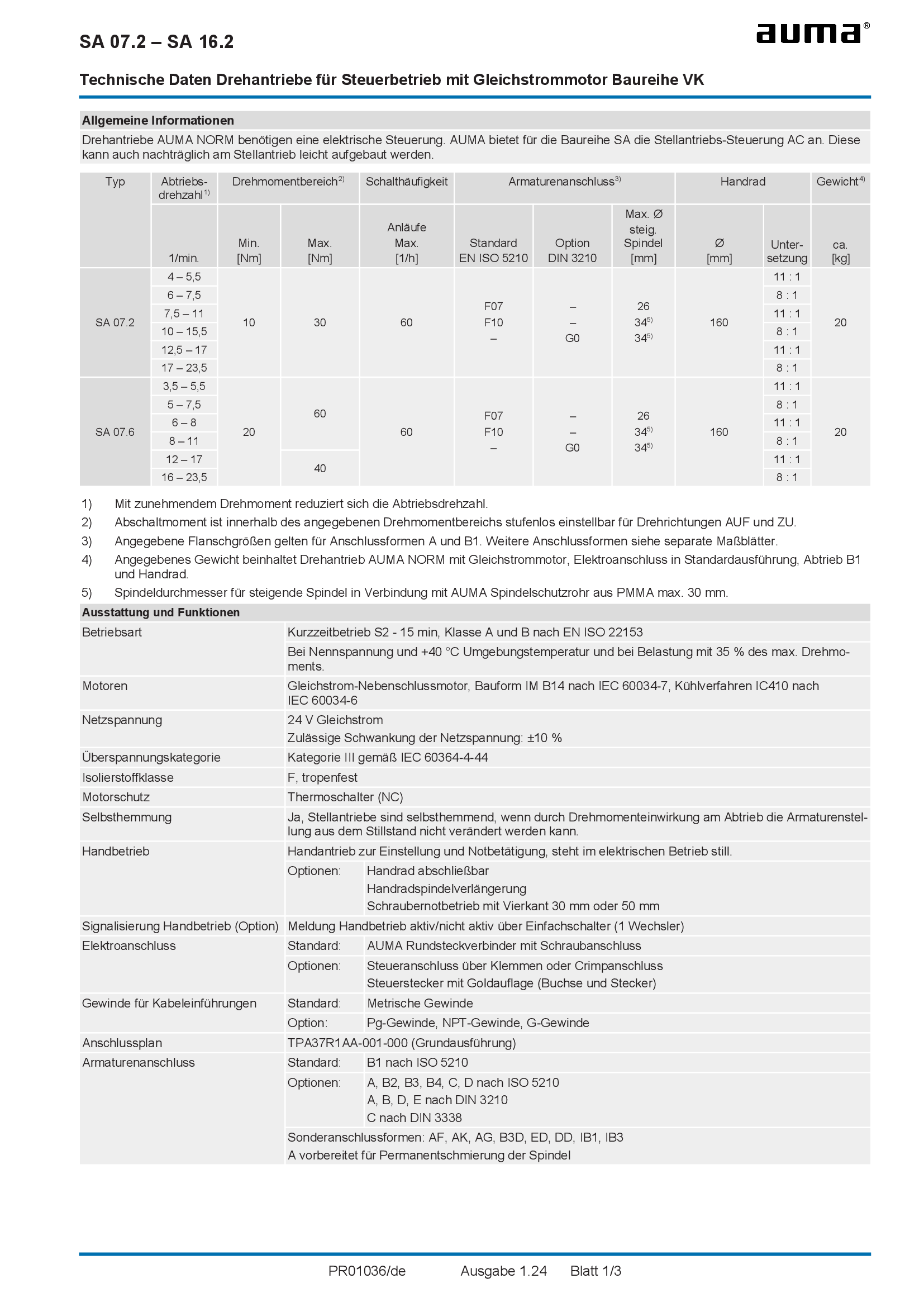
Multi-turn actuators SA 07.2 - 07.6, open-close duty, DC motors of type range VK
Technical data
Multi-turn actuators SA 07.2 - 14.6, open-close duty, 1-phase AC
Technical data
Multi-turn actuators SA 07.2 - 16.2, Torques at different running times, Short-time duty S2 - 15 min
Technical data

Multi-turn actuators SA 07.2 - 16.2, Torques at different running times, Short-time duty S2 - 30 min
Technical data
Multi-turn actuators SA 07.2 - 16.2, manuel force at handwheel
Technical data
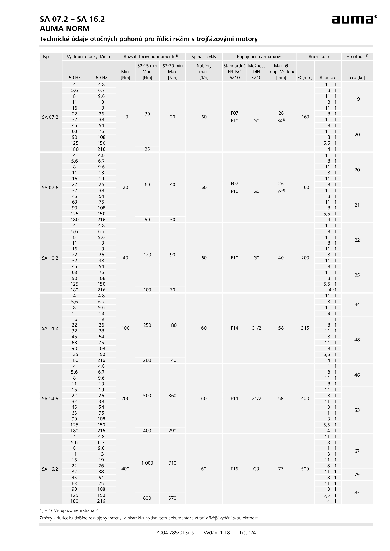
Multi-turn actuators SA 07.2 - 16.2, open-close duty, 3-phase AC
Technical data
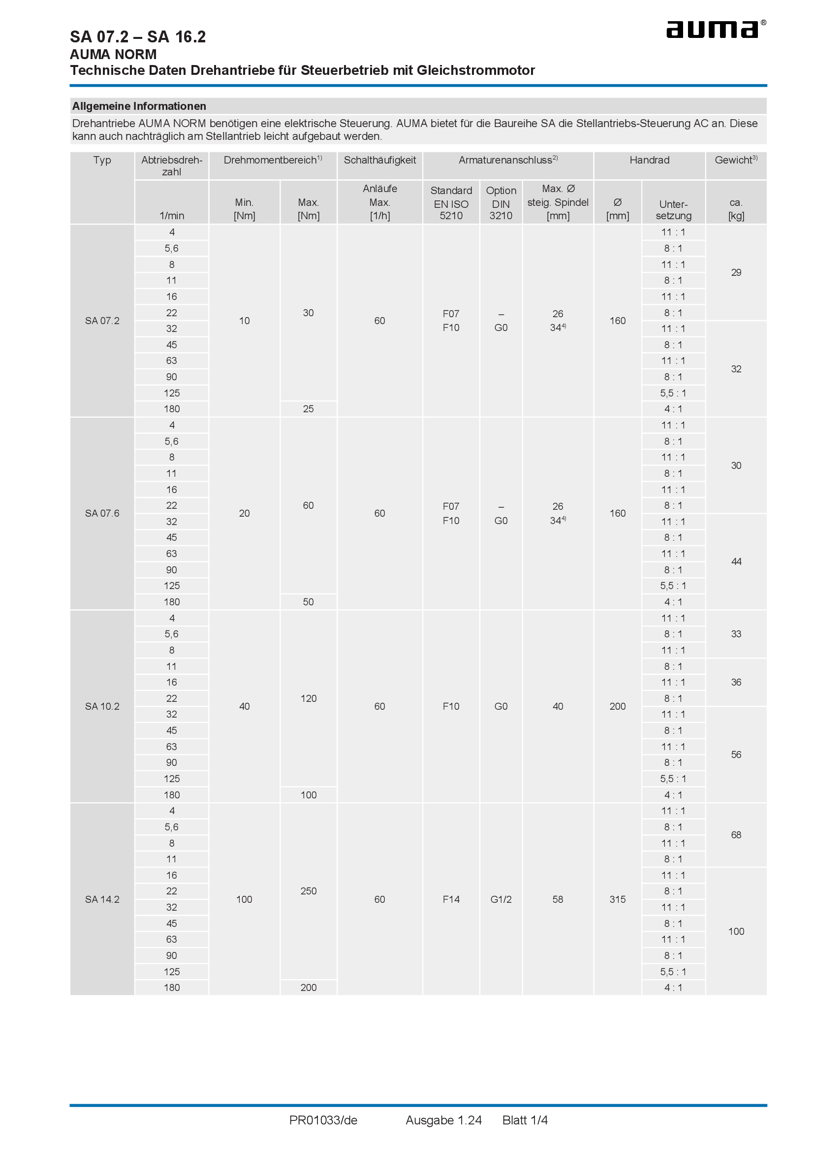
Multi-turn actuators SA 07.2 - 16.2, open-close duty, DC
Technical data

Multi-turn actuators SA 07.2 - 16.2, open-close duty, brake motors
Technical data
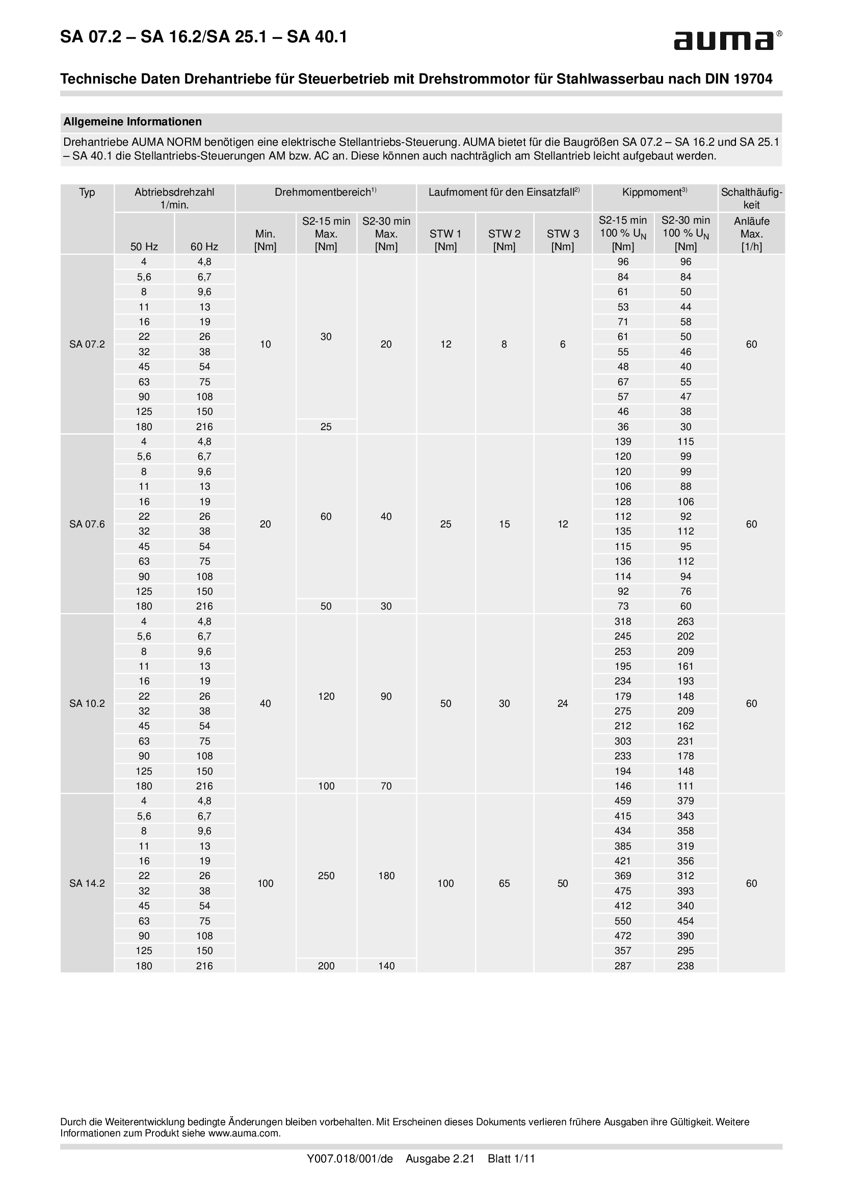
Multi-turn actuators SA 07.2 - 16.2/SA 25.1 - SA 40.1, open-close duty, 3-phase AC, for hydraulic steel structures
Technical data

Multi-turn actuators SA 07.2-UW - SA 16.2-UW, open-close duty, 3-phase AC, for continuous underwater use
Technical data

Multi-turn actuators SA 25.1 - 40.1, open-close duty, brake motors
Technical data
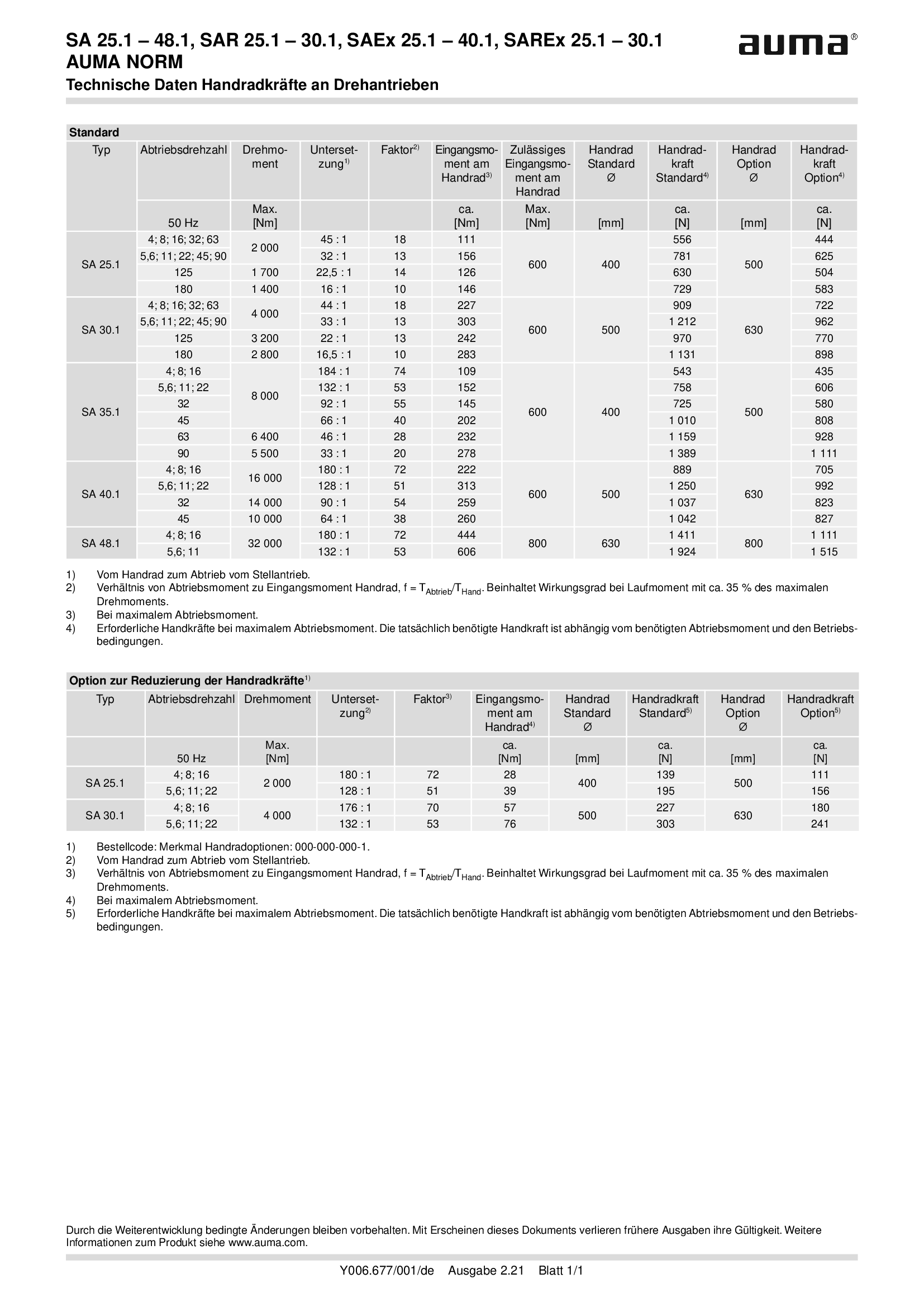
Multi-turn actuators SA 25.1 - 48.1, manuel force at handwheel
Technical data
Multi-turn actuators SA 25.1 - 48.1, open-close duty, 3-phase AC
Technical data

Multi-turn actuators SA 25.1 - 48.1/SAEx 25.1 - 40.1, Torques for differential voltages, Short-time duty S2 - 15 min
Technical data
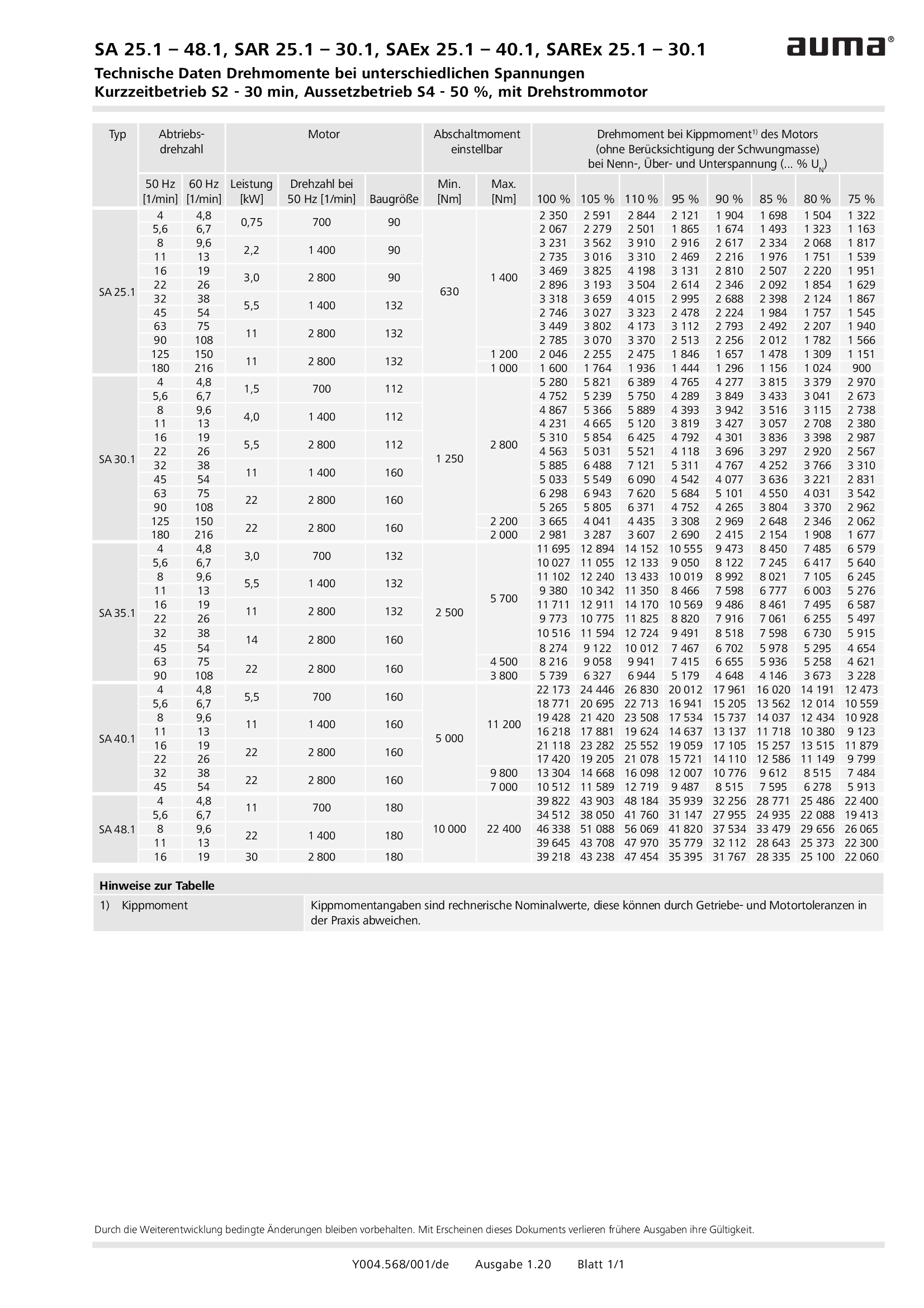
Multi-turn actuators SA 25.1 - 48.1/SAEx 25.1 - 40.1, Torques for differential voltages, Short-time duty S2 - 30 min
Technical data
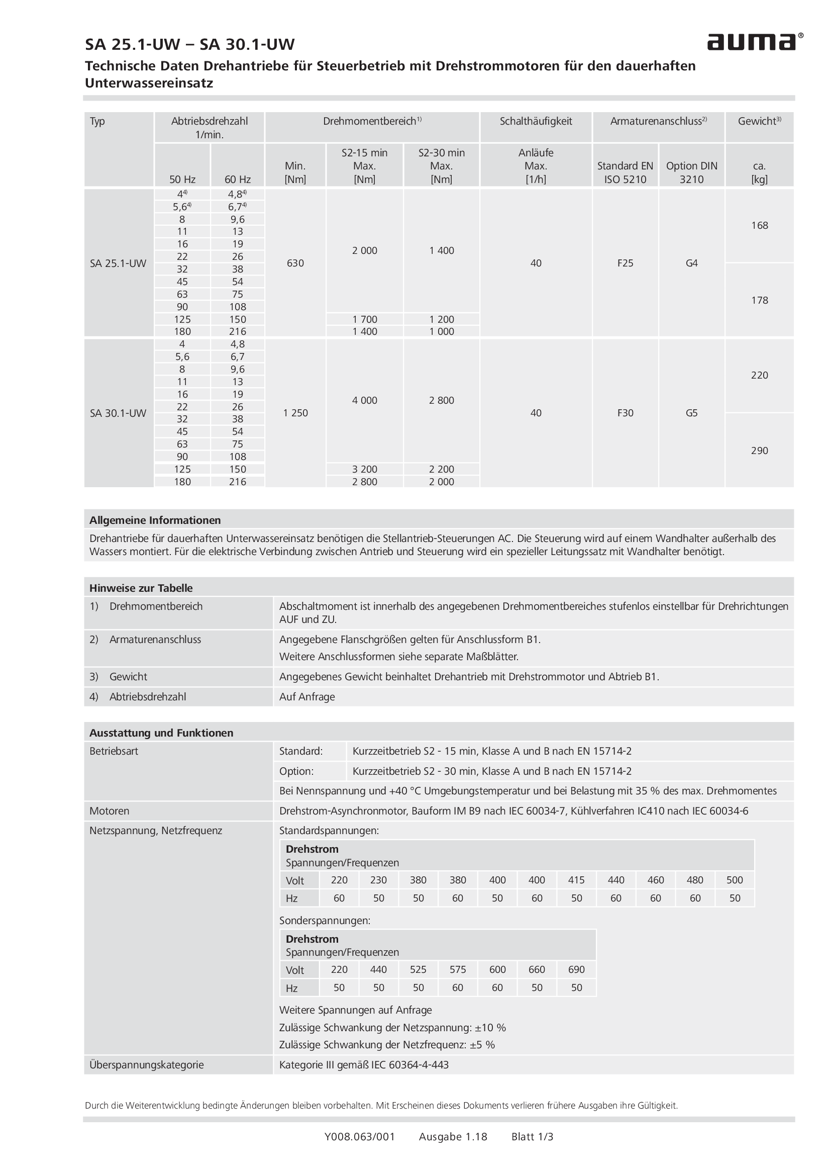
Multi-turn actuators SA 25.1-UW - SA 30.1-UW, open-close duty, 3-phase AC, for continuous underwater use
Technical data
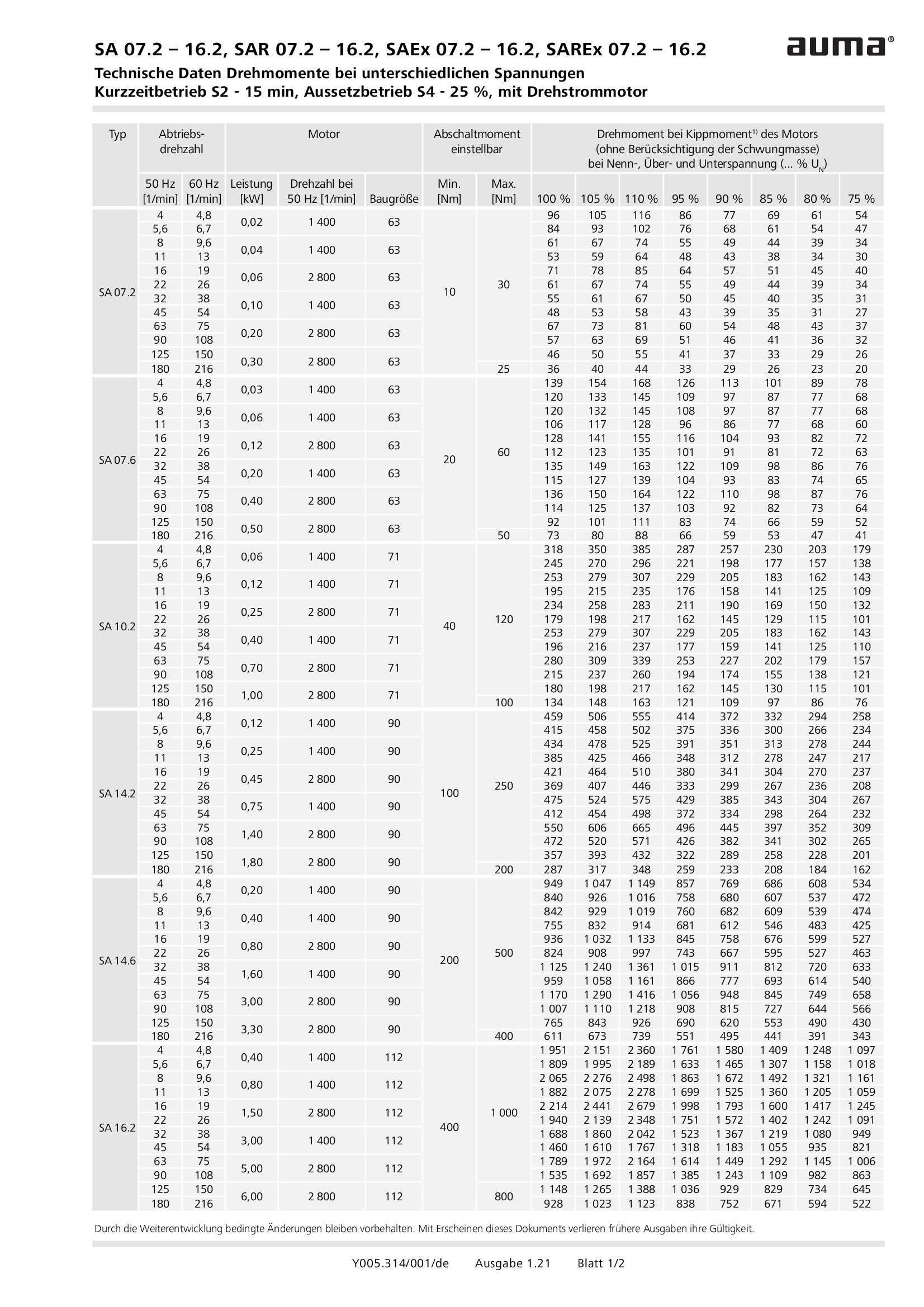
Multi-turn actuators SA/SAR 07.2 - 16.2 / SAEx/SAREx 07.2 - 16.2, Torques for differential voltages, Short-time duty S2 - 15 min, Intermittent duty S4 - 25 %
Technical data
Multi-turn actuators SA/SAR 07.2 - 16.2 / SAEx/SAREx 07.2 - 16.2, Torques for differential voltages, Short-time duty S2 - 30 min, Intermittent duty S4 -50 %
Technical data
Multi-turn actuators SAI 07.1 - 35.1 , open-close duty, nuclear power plants, TU3791-003-38959426-2007
Technical data
Multi-turn actuators SAI 07.2 - 16.2 , modulating duty, nuclear power plants, IEEE 382-2006
Technical data

Multi-turn actuators SAI 07.2 - 16.2 , open-close duty, nuclear power plants, IEEE 382-2006
Technical data

Multi-turn actuators SAI 25.1 - 35.1 , open-close duty, nuclear power plants, IEEE 382-2006
Technical data
Multi-turn actuators SAI 6 - 100 , open-close duty, nuclear power plants, IEEE 382-1978
Technical data
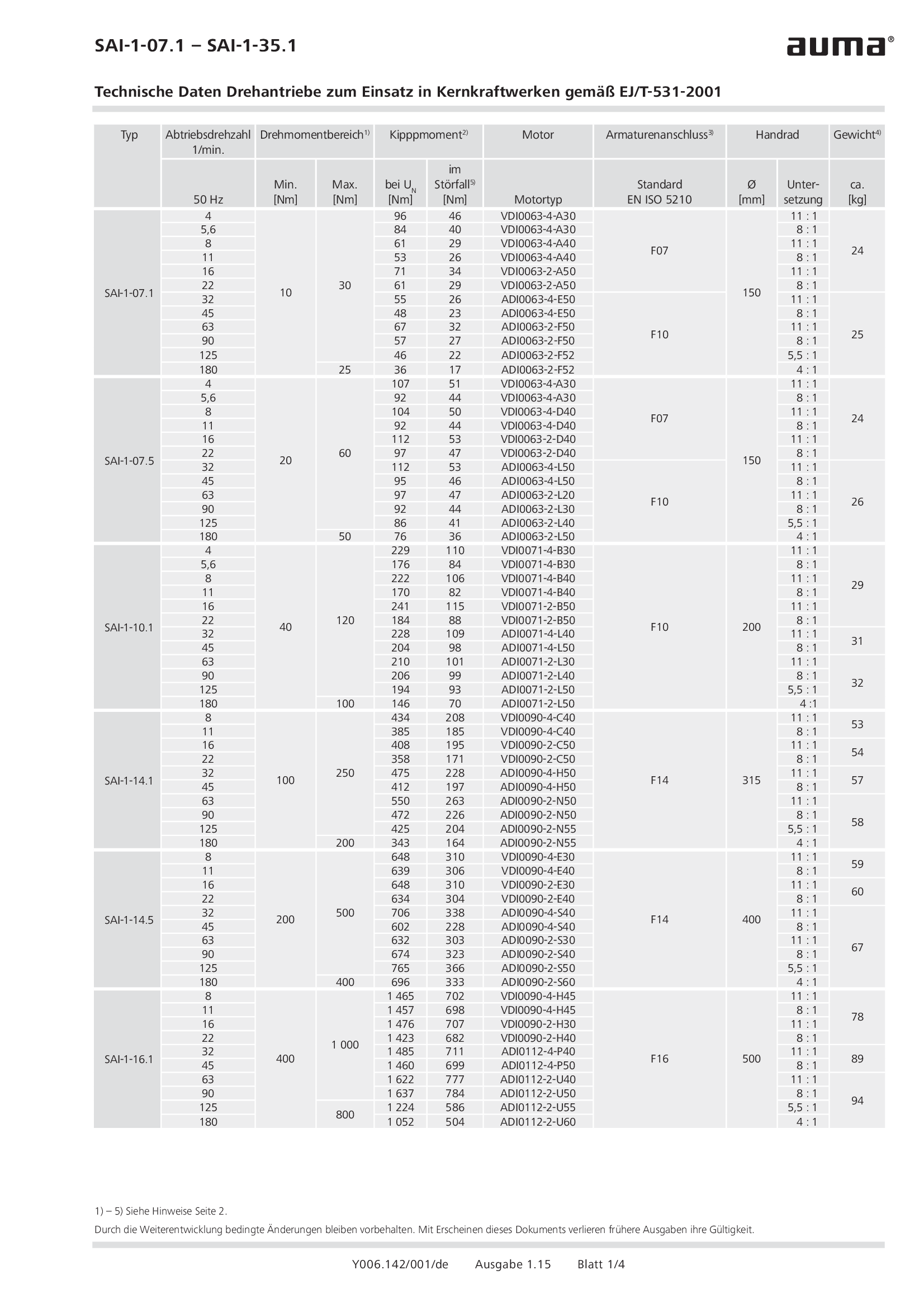
Multi-turn actuators SAI-1-07.1 - 35.1, open-close duty, nuclear power plants, EJ/T-531-2001
Technical data
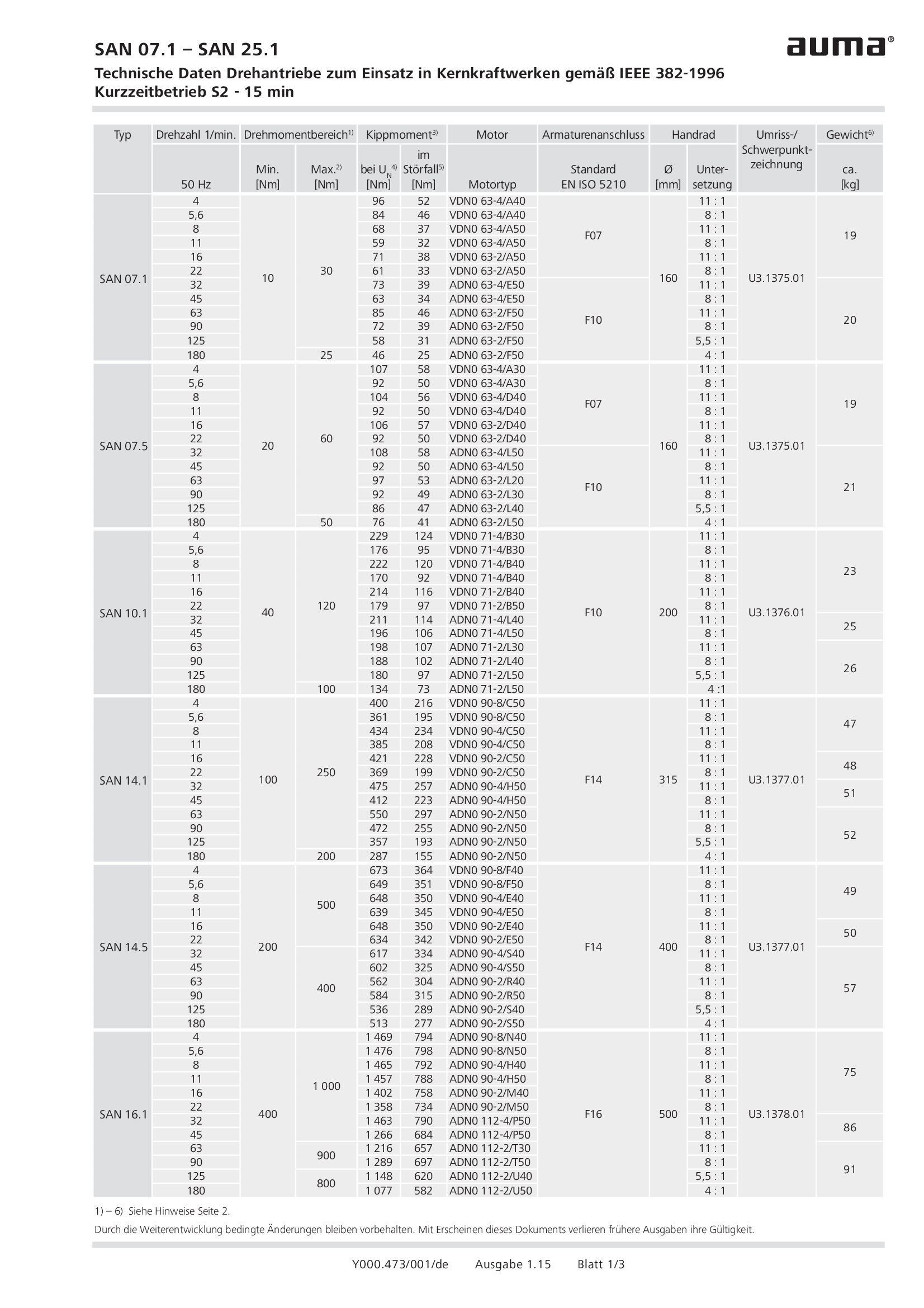
Multi-turn actuators SAN 07.1 - 25.1 , open-close duty, nuclear power plants, IEEE 382-1996
Technical data
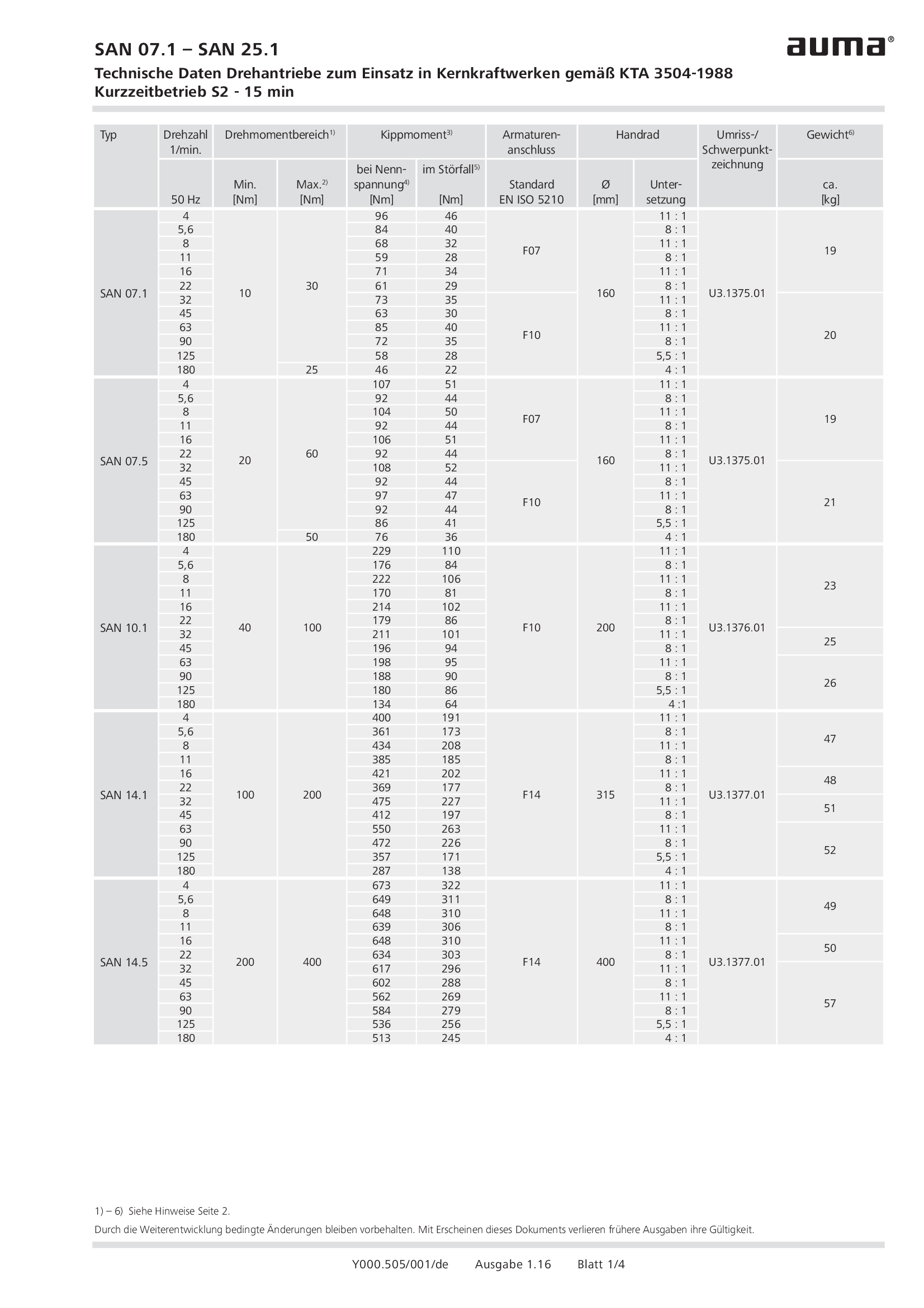
Multi-turn actuators SAN 07.1 - 25.1, open-close duty, nuclear power plants, KTA 3504-1988
Technical data
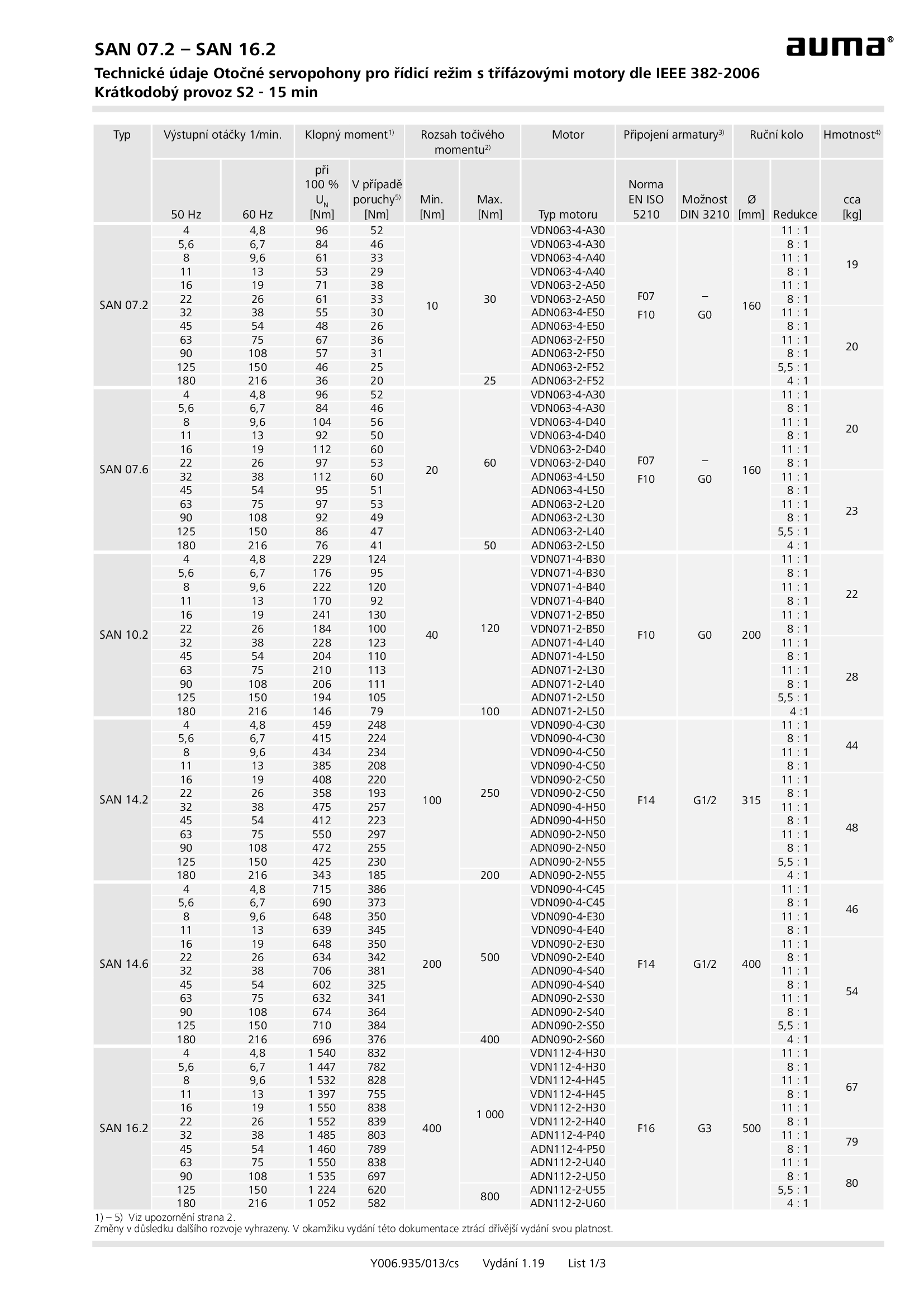
Multi-turn actuators SAN 07.2 - 16.2, open-close duty, nuclear power plants, IEEE 382-2006
Technical data
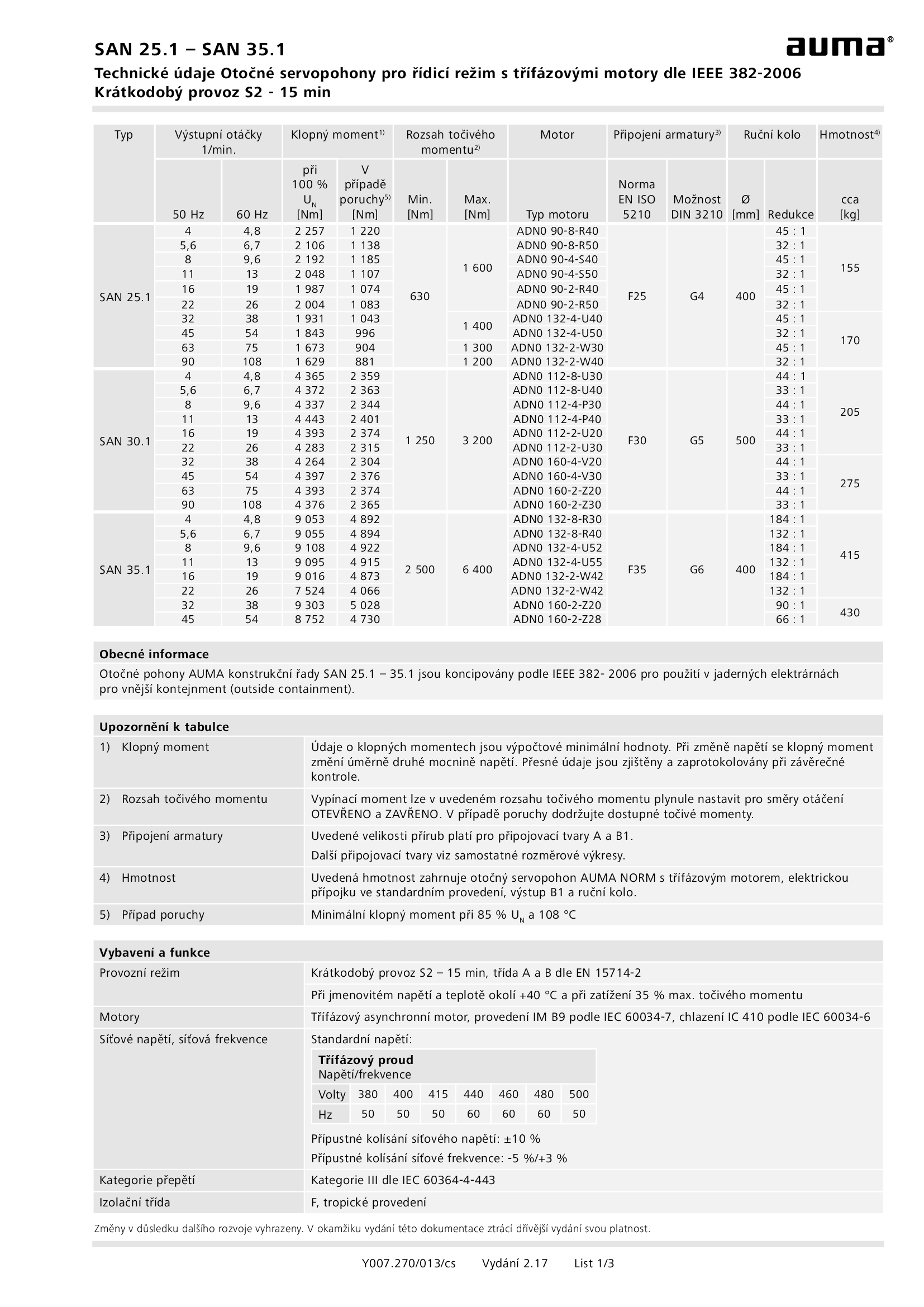
Multi-turn actuators SAN 25.1 - 35.1 , open-close duty, nuclear power plants, IEEE 382-2006
Technical data
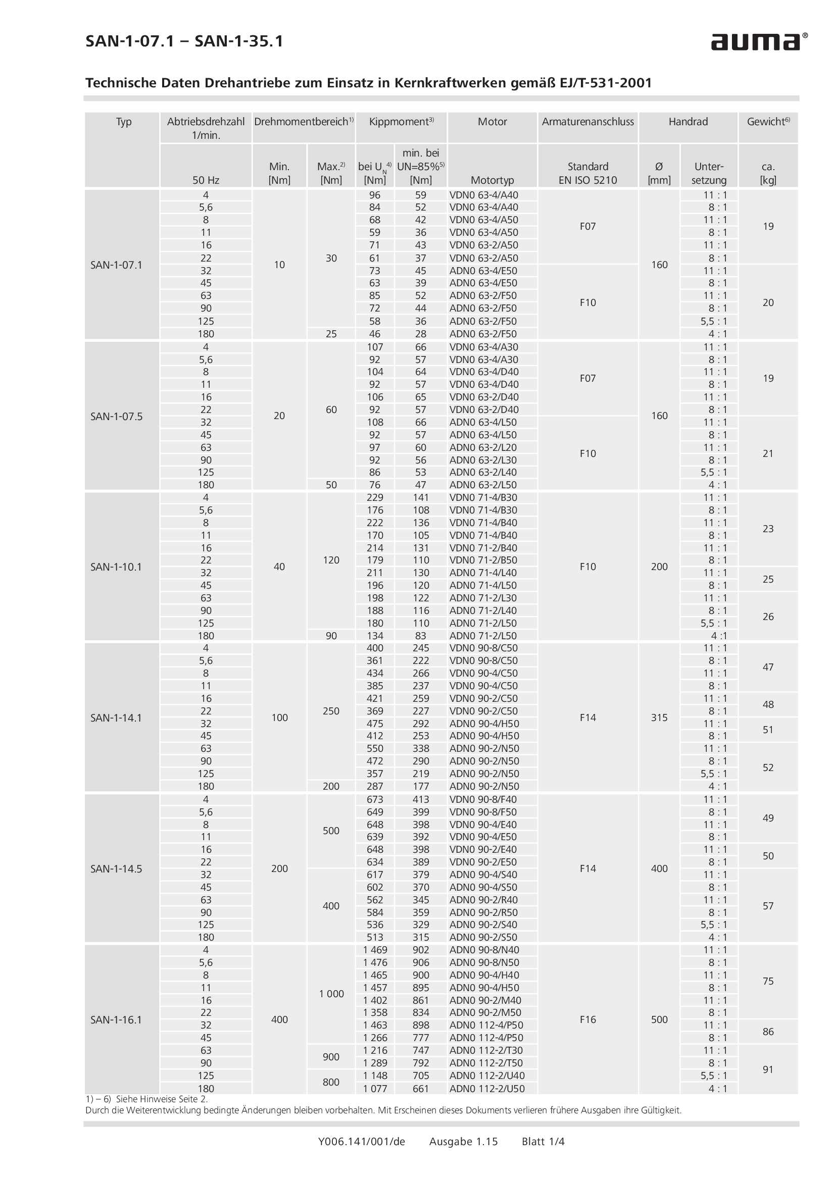
Multi-turn actuators SAN-1-07.1 - 35.1 , open-close duty, nuclear power plants, EJ/T-531-2001
Technical data

Multi-turn actuators SARI 07.1 - 30.1 , modulating duty, nuclear power plants, TU3791-003-38959426-2007
Technical data

Multi-turn actuators SARI 25.1 - 30.1 , modulating duty, nuclear power plants, IEEE 382-2006
Technical data
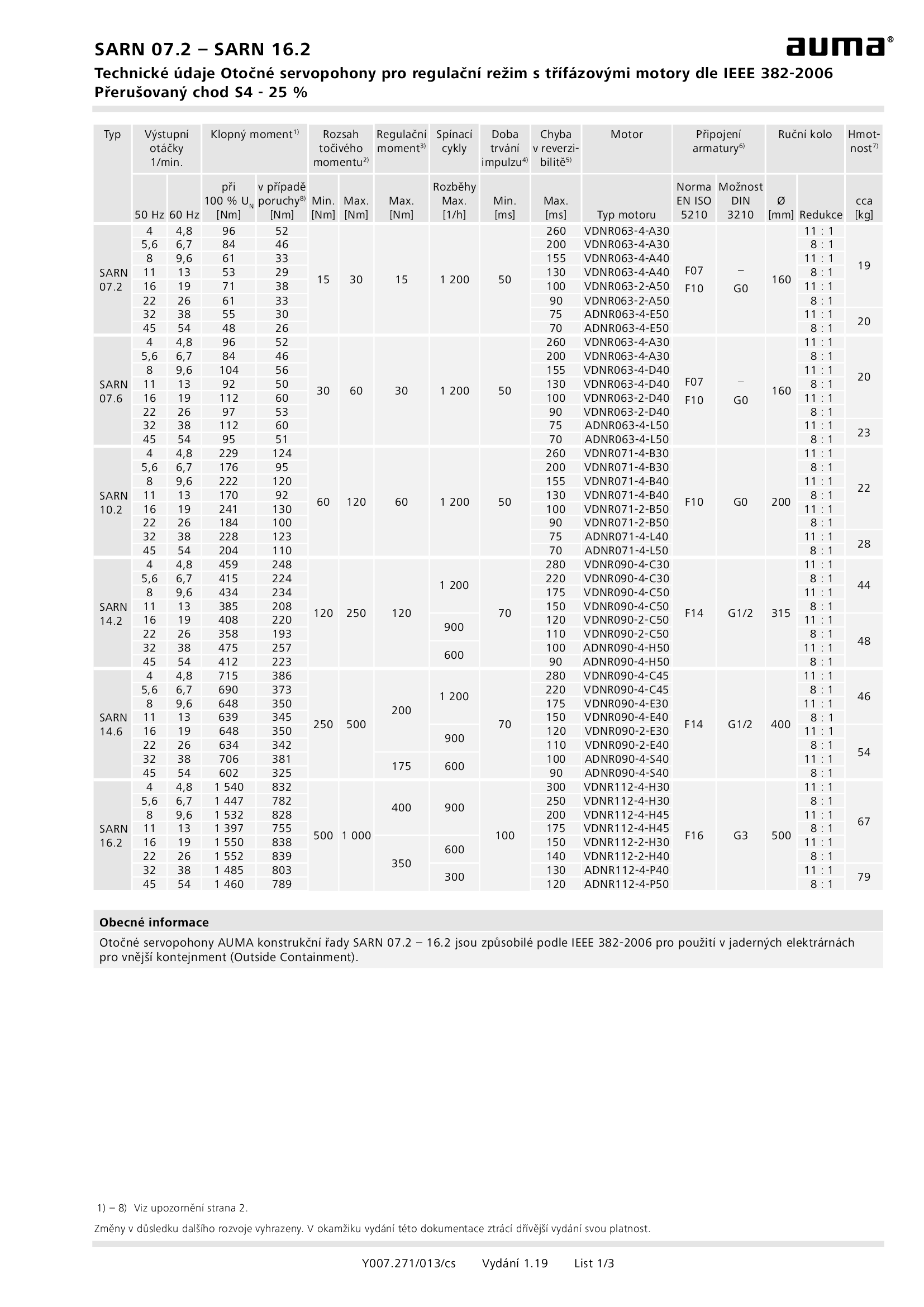
Multi-turn actuators SARN 07.2 - 16.2, modulating duty, nuclear power plants, IEEE 382-2006
Technical data
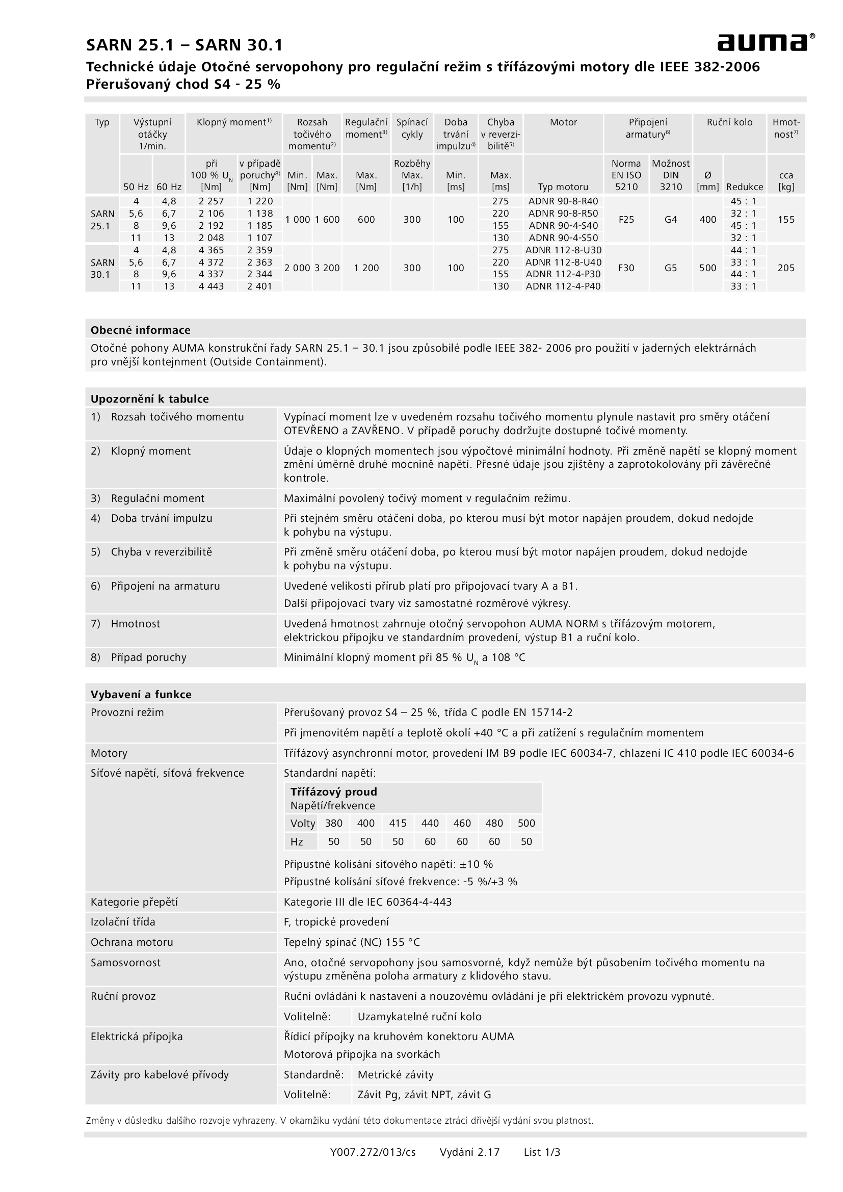
Multi-turn actuators SARN 25.1 - 30.1 , modulating duty, nuclear power plants, IEEE 382-2006
Technical data
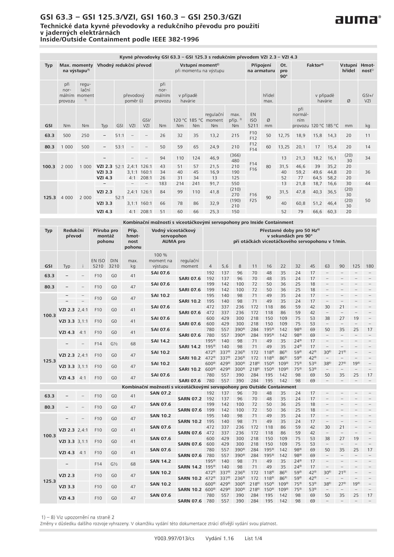
Part-turn gearboxes GSI 63.3 - 250.3, VZI/GZI, nuclear power plants, IEEE 382-1996
Technical data
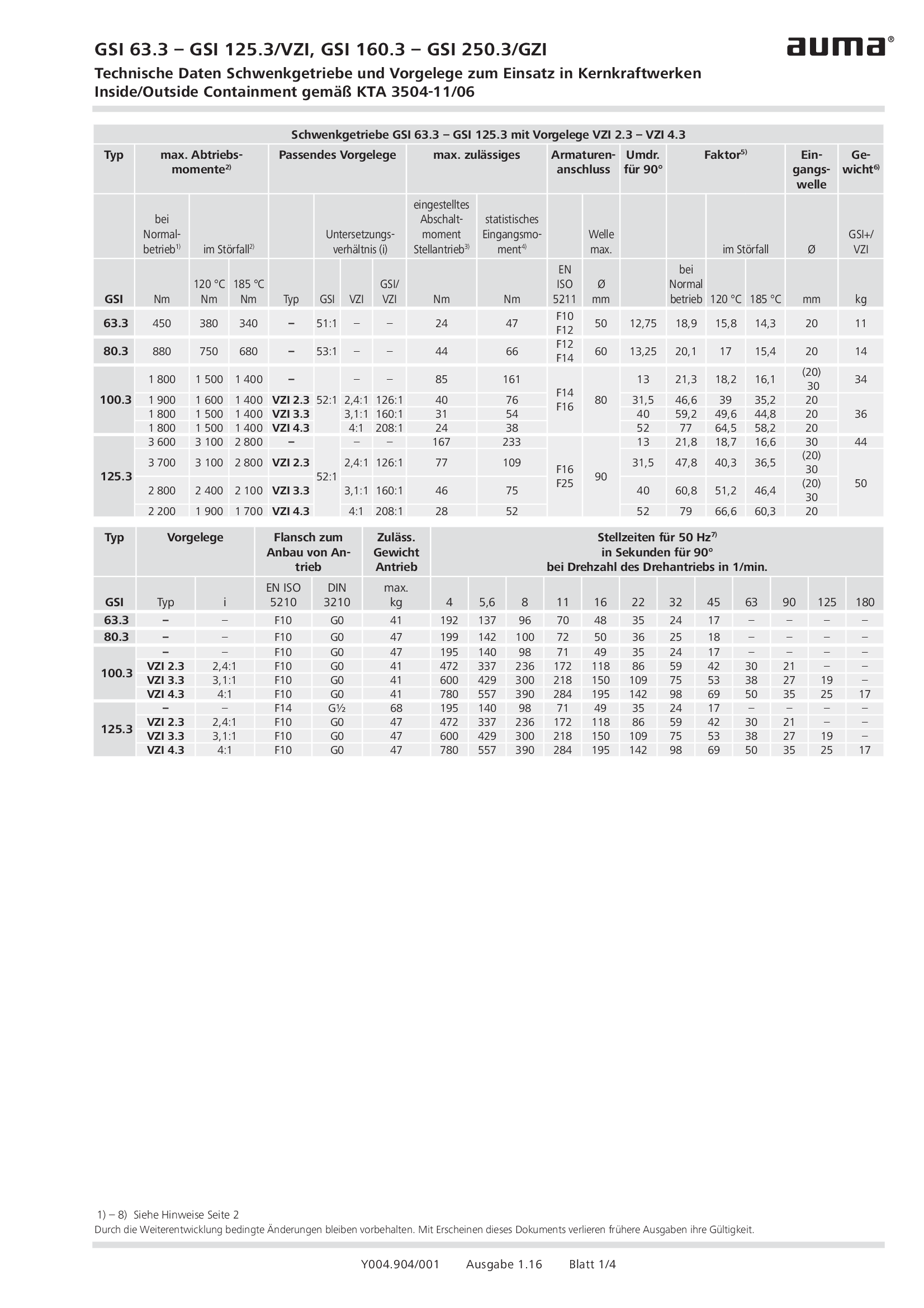
Part-turn gearboxes GSI 63.3 - 250.3, VZI/GZI, nuclear power plants, KTA 3504-11/09
Technical data
Power tool for emergency operation for multi-turn actuators SA .1
Technical data
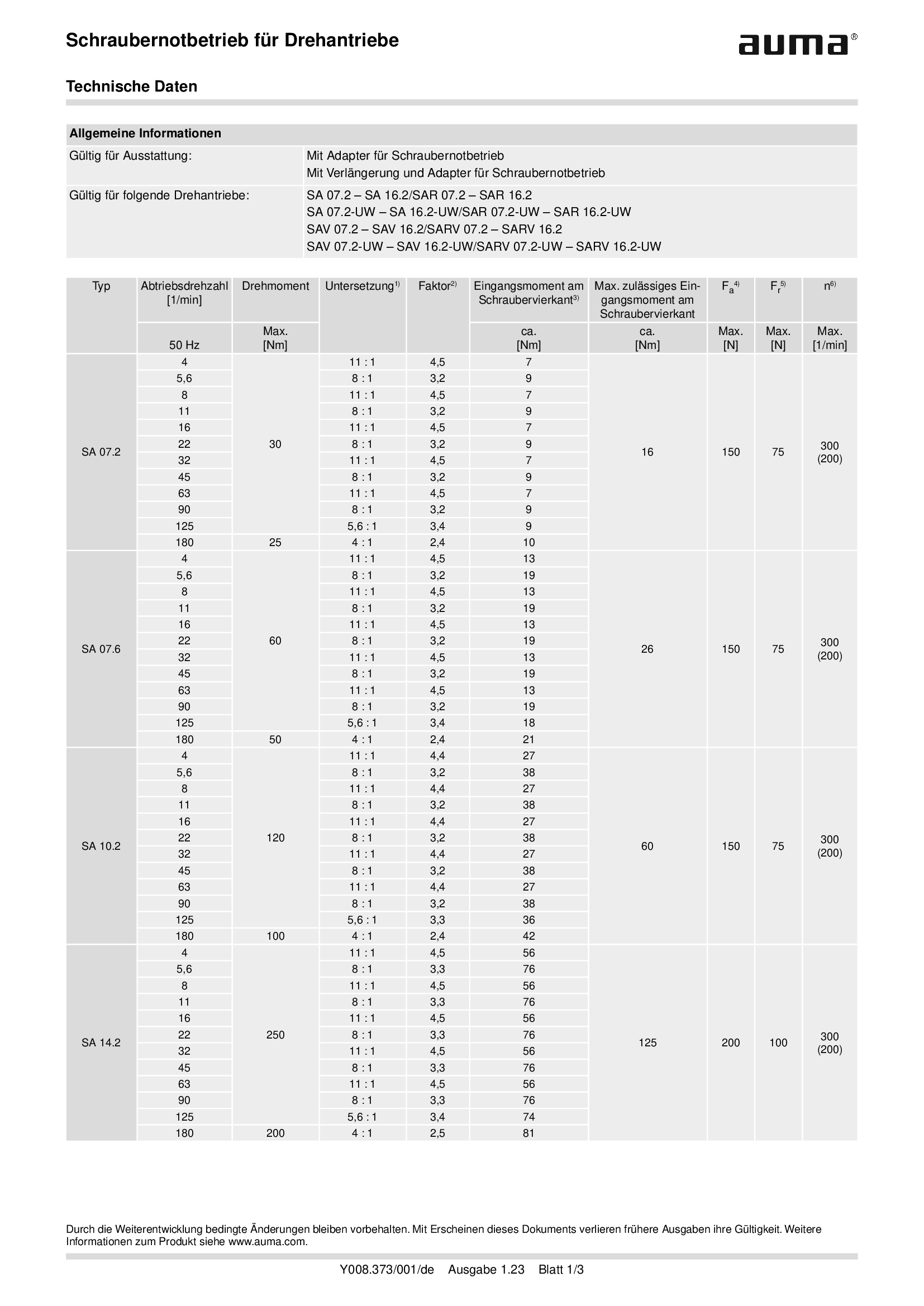
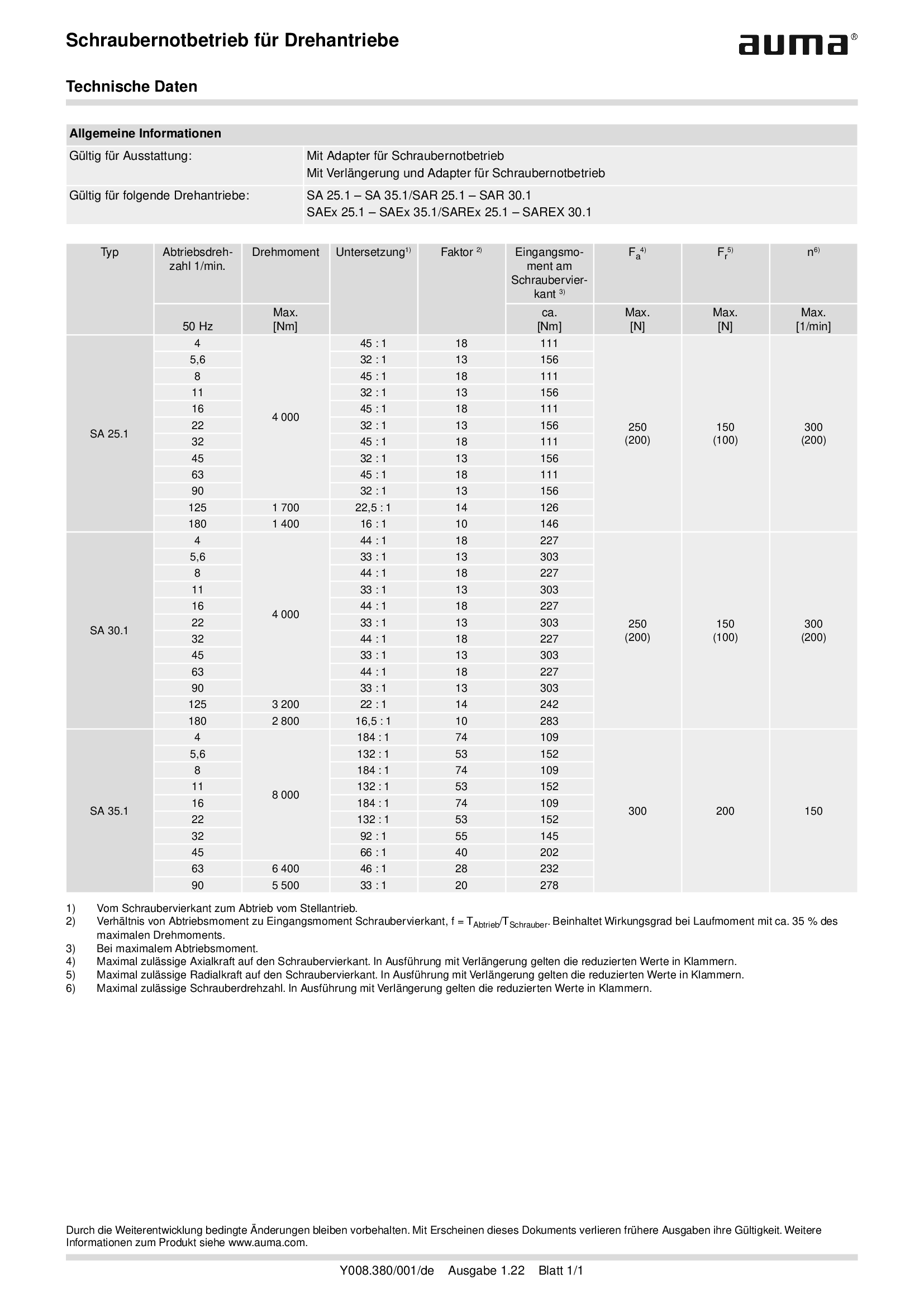
Power tool for emergency operation for multi-turn actuators SA .2
Technical data
Power tool for emergency operation for multi-turn actuators SAEx .2 and TIGRON
Technical data
Technical description
Supplement AUMATIC AC 01.2/ACExC 01.2, version actuators: with elektronic control unit (MWG) and SIL limit switching
Technical description
Supplement AUMATIC AC 01.2/ACExC 01.2, version actuators: with elektronic control unit (MWG) and limit switching
Technical description
Wiring diagram

A1: AUMATIC AC 01.2 position feedback signal 0/4 - 20 mA (potentiometer in actuator), basic version, reversing contactors OPEN, STOP, CLOSE, EMERGENCY (24 V DC), 6 programmable output contacts, AUMA power class A1 - A3
Wiring diagram

A1: AUMATIC ACExC 01.2 position feedback signal 0/4 - 20 mA (potentiometer in actuator),basic version, reversing contactors CLOSE, OPEN, STOP, EMERGENCY (24 V DC), 6 programmable output contacts, AUMA power class A1 - A3
Wiring diagram

A1N: AUMATIC AC 01.2 position/torque feedback signal 0/4 - 20 mA (MWG in actuator), reversing contactors OPEN, STOP, CLOSE, EMERGENCY (24 V DC), 6 programmable output contacts, AUMA power class A1 - A3
Wiring diagram

A1N: AUMATIC ACExC 01.2 position/torque feedback signal 0/4 - 20 mA (MWG in actuator), reversing contactors CLOSE, OPEN, STOP, EMERGENCY (24 V DC), 6 programmable output contacts, AUMA power class A1 - A3
Wiring diagram

A2: AUMATIC AC 01.2 positioner and postition feedback signal 0/4 - 20 mA (potentiometer in actuator), reversing contactors OPEN, STOP, CLOSE, EMERGENCY, MODE (24 V DC), 6 programmable output contacts, AUMA power class A1 - A3
Wiring diagram

A2: AUMATIC ACExC 01.2 positioner and position feedback signal 0/4 - 20 mA (potentiometer in actuator), reversing contactors MODE, CLOSE, OPEN, STOP, EMERGENCY (24 V DC), setpoint (0/4 - 20 mA), 6 programmable output contacts, AUMA power class A1 -
Wiring diagram

A2DP: AUMATIC AC 01.2 position feedback (potentiometer in actuator), basic version, reversing contactors, Profibus, AUMA power class A1 - A3
Wiring diagram

A2DP: AUMATIC ACExC 01.2 position feedback (potentiometer in actuator), basic version, reversing contactors, Profibus, AUMA power class A1 - A3
Wiring diagram

A2ENIP: AUMATIC AC 01.2 position feedback (potentiometer in actuator), basic version, reversing contactors, Ethernet/IP, AUMA power class A3 - A3
Wiring diagram

A2ENIP: AUMATIC ACExC 01.2 position feedback (potentiometer in actuator), basic version, reversing contactors, EtherNet/IP, AUMA power class A1 - A3
Wiring diagram

A2FF: AUMATIC AC 01.2 position feedback (potentiometer in actuator), basic version, Reversing contactors, Foundation Fieldbus FF, AUMA power classes A1 – A3
Wiring diagram

A2FF: AUMATIC ACExC 01.2 position feedback (potentiometer in actuator), basic version, reversing contactors, Foundation Fieldbus FF, AUMA power class A1 - A3
Wiring diagram

A2HRT: AUMATIC AC 01.2 position feedback (potentiometer in actuator), basic version, Reversing contactors, HART actuatorAUMA power classes A1 – A3
Wiring diagram

A2HRT: AUMATIC ACExC 01.2 position feedback (potentiometer in actuator), reversing contactors, HART actuator, AUMA power class A1 - A3
Wiring diagram

A2HRTCO: AUMATIC AC 01.2 position feedback (potentiometer in actuator), basic version, Reversing contactors, HART Current Output, AUMA power classes A1 – A3
Wiring diagram

A2HRTCO: AUMATIC ACExC 01.2 position feedback (potentiometer in actuator), basic version, reversing contactors, HART current output, AUMA power class A1 - A3
Wiring diagram

A2MB: AUMATIC AC 01.2 position feedback (potentiometer in actuator), basic version, reversing contactors, Modbus RTU, AUMA power class A1 - A3
Wiring diagram

A2MB: AUMATIC ACExC 01.2 position feedback (potentiometer in acuator), basic version, reversing contactors, Modbus, AUMA power class A1 - A3
Wiring diagram

A2MBTCP: AUMATIC AC 01.2 position feedback (potentiometer in actuator), basic version, Reversing contactors, Modbus TCP/IP, AUMA power classes A1 – A3
Wiring diagram

A2MBTCP: AUMATIC AC 01.2 position/torque feedback (MWG in actuator), Reversing contactors, Modbus TCP/IP, AUMA power classes A1 – A3
Wiring diagram

A2MBTCP: AUMATIC ACExC 01.2 position feedback (potentiometer in actuator), basic version, reversing contactors, Modbus TCP/IP, AUMA power class A1 - A3
Wiring diagram

A2N: AUMATIC AC 01.2 positioner and position/torque feedback signal 0/4 - 20 mA (MWG in actuator), , reversing contactors OPEN, STOP, CLOSE, EMERGENCY, MODE (24 V DC), 6 programmable output contacts, AUMA power class A1 - A3
Wiring diagram

A2N: AUMATIC ACExC 01.2 positioner and position/torque feedback signal 0/4 - 20 mA (MWG in actuator), reversing contactors MODE, CLOSE, OPEN, STOP, EMERGENCY (24 V DC), 6 programmable output contacts, AUMA power class A1 - A3
Wiring diagram

A2NDP: AUMATIC AC 01.2 position/torque feedback (MWG in actuator), reversing contactors, Profibus, AUMA power class A1 - A3
Wiring diagram

A2NDP: AUMATIC ACExC 01.2 position/torque feedback (MWG in actuator), reversing contactors, Profibus, AUMA power class A1 - A3
Wiring diagram

A2NENIP: AUMATIC AC 01.2, position/torque feedback (MWG in actuator, reversing contactors, Ethernet/IP, AUMA power class A1 - A 3
Wiring diagram

A2NENIP: AUMATIC ACExC 01.2 position/torque feedback (MWG in actuator), reversing contactors, EtherNet/IP, AUMA power class A1 - A3
Wiring diagram

A2NFF: AUMATIC AC 01.2 position/torque feedback (MWG in actuator), Reversing contactors, Foundation Fieldbus FF, AUMA power classes A1 – A3
Wiring diagram

A2NFF: AUMATIC ACExC 01.2 position/torque feedback (MWG in actuator), reversing contactors, Foundation Fieldbus FF, AUMA power class A1 - A3
Wiring diagram

A2NHRT: AUMATIC AC 01.2 position/torque feedback (MWG in actuator), Reversing contactors, HART actuator, AUMA power classes A1 – A3
Wiring diagram

A2NHRT: AUMATIC ACExC 01.2 position/torque feedback (MWG in actuator), reversing contactors, HART actuator, AUMA power class A1 - A3
Wiring diagram

A2NHRTCO: AUMATIC AC 01.2 position/torque feedback (MWG in actuator), Reversing contactors, HART Current Output, AUMA power classes A1 – A3
Wiring diagram

A2NHRTCO:AUMATIC ACExC 01.2 position/torque feedback (MWG in actuator), reversing contactors, HART current output, AUMA power class A1 - A3
Wiring diagram

A2NMB: AUMATIC AC 01.2 position/torque feedback (MWG in actuator), reversing contactors, Modbus RTU, AUMA power class A1 - A3
Wiring diagram

A2NMB: AUMATIC ACExC 01.2 position/torque feedback (MWG in actuator), reversing contactors, Modbus, AUMA power class A1 - A3
Wiring diagram

A2NMBTCP: AUMATIC ACExC 01.2 position/torque feedback (MWG in actuator), reversing contactors, Modbus TCP/IP, AUMA power class A1 - A3
Wiring diagram

A3: AUMATIC AC 01.2 positioner and position feedback signal 0/4 - 20 mA (potentiometer in actuator), thyristors OPEN, STOP, CLOSE, EMERGENCY, MODE (24 V DC), 6 programmable output contacts, AUMA power class B1/B2
Wiring diagram

A3: AUMATIC AC 01.2 positioner and position feedback signal 0/4 - 20 mA (potentiometer in actuator), thyristors OPEN, STOP, CLOSE, EMERGENCY, MODE (24 V DC), 6 programmable output contacts, AUMA power class B3
Wiring diagram

A3: AUMATIC ACExC 01.2 positioner and position feedback signal 0/4 - 20 mA (potentiometer in actuator), thyristors MODE, CLOSE, OPEN, STOP, EMERGENCY (24 V DC), setpoint (0/4 - 20 mA) 6 programmable output contacts, AUMA power class B1/B2
Wiring diagram

A3: AUMATIC ACExC 01.2 positioner and position feedback signal 0/4 - 20 mA (potentiometer in actuator), thyristors MODE, CLOSE, OPEN, STOP, EMERGENCY (24 V DC), setpoint (0/4 - 20 mA) 6 programmable output contacts, AUMA power class B3
Wiring diagram

A3DP: AUMATIC AC 01.2 position feedback (potentiometer in actuator), thyristors, Profibus, AUMA power class B1/B2
Wiring diagram

A3DP: AUMATIC AC 01.2 position feedback (potentiometer in actuator), thyristors, Profibus, AUMA power class B2
Wiring diagram

A3DP: AUMATIC ACExC 01.2 position feedback (potentiometer in actuator), thyristors, Profibus, AUMA power class B1/B2
Wiring diagram

A3DP: AUMATIC ACExC 01.2 position feedback (potentiometer in actuator), thyristors, Profibus, AUMA power class B3
Wiring diagram

A3ENIP: AUATIC AC 01.2 postition feedback (potentiometer in actuator), Thyristors, EtherNet/IP, AUMA power class B1/B2
Wiring diagram

A3ENIP: AUATIC AC 01.2 postition feedback (potentiometer in actuator), Thyristors, EtherNet/IP, AUMA power class B3
Wiring diagram

A3ENIP: AUATIC ACExC 01.2 position feedback (potentiometer in actuator), Thyristors, EtherNet/IP, AUMA power class B1/B2
Wiring diagram

A3ENIP: AUATIC ACExC 01.2 position feedback (potentiometer in actuator), Thyristors, EtherNet/IP, AUMA power class B3
Wiring diagram

A3FF: AUMATIC AC 01.2 position feedback (potentiometer in actuator), Thyristors, Foundation Fieldbus FF, AUMA power class B1/B2
Wiring diagram

A3FF: AUMATIC AC 01.2 position feedback (potentiometer in actuator), Thyristors, Foundation Fieldbus FF, AUMA power class B3
Wiring diagram

A3FF: AUMATIC ACExC 01.2 position feedback (potentiometer in actuator), Thyristors, Foundation Fieldbus FF, AUMA power class B1/B2
Wiring diagram

A3FF: AUMATIC ACExC 01.2 position feedback (potentiometer in actuator), Thyristors, Foundation Fieldbus FF, AUMA power class B3
Wiring diagram

A3HRT: AUMATIC AC 01.2 position feedback (potentiometer in actuator), Thyristors, HART actuator, AUMA power class B1/B2
Wiring diagram

A3HRT: AUMATIC AC 01.2 position feedback (potentiometer in actuator), Thyristors, HART actuator, AUMA power class B3
Wiring diagram

A3HRT: AUMATIC ACExC 01.2 position feedback (potentiometer in actuator) Thyristors, HART actuator, AUMA power class B1/B2
Wiring diagram

A3HRT: AUMATIC ACExC 01.2 position feedback (potentiometer in actuator) Thyristors, HART actuator, AUMA power class B3
Wiring diagram

A3HRTCO: AUMATIC AC 01.2 position feedback (potentiometer in actuator), Thyristors, HART Current Output, AUMA power class B1/B2
Wiring diagram

A3HRTCO: AUMATIC AC 01.2 position feedback (potentiometer in actuator), Thyristors, HART Current Output, AUMA power class B3
Wiring diagram

A3HRTCO: AUMATIC ACExC 01.2 position feedback (potentiometer in actuator), Thyristors, HART current output, AUMA power class B1/B2
Wiring diagram

A3HRTCO: AUMATIC ACExC 01.2 position feedback (potentiometer in actuator), Thyristors, HART current output, AUMA power class B3
Wiring diagram

A3MB: AUMATIC AC 01.2 position feedback (potentiometer in actuator), thyristors, Modbus, AUMA power class B1/B2
Wiring diagram

A3MB: AUMATIC AC 01.2 position feedback (potentiometer in actuator), thyristors, Modbus, AUMA power class B3
Wiring diagram

A3MB: AUMATIC ACExC 01.2 position feedback (potentiometer in actuator), thyristors, Modbus, AUMA power class B1/B2
Wiring diagram

A3MB: AUMATIC ACExC 01.2 position feedback (potentiometer in actuator), thyristors, Modbus, AUMA power class B3
Wiring diagram

A3MBTCP: AUMATIC AC 01.2 position feedback (potentiometer in actuator), Thyristors, Modbus TCP/IP, AUMA power class B1/B2
Wiring diagram

A3MBTCP: AUMATIC AC 01.2 position feedback (potentiometer in actuator), Thyristors, Modbus TCP/IP, AUMA power class B3
Wiring diagram

A3MBTCP: AUMATIC ACExC 01.2 position feedback (potentiometer in actuator), Thyristors, Modbus TCP/IP, AUMA power class B1/B2
Wiring diagram

A3MBTCP: AUMATIC ACExC 01.2 position feedback (potentiometer in actuator), Thyristors, Modbus TCP/IP, AUMA power class B3
Wiring diagram

A3N: AUMATIC AC 01.2 positioner and position/torque feedback signal 0/4 - 20 mA (MWG in actuator), thyristors OPEN, STOP, CLOSE, EMERGENCY, MODE (24 V DC), 6 programmable output contacts, AUMA power class B1/B2
Wiring diagram

A3N: AUMATIC AC 01.2 positioner and position/torque feedback signal 0/4 - 20 mA (MWG in actuator), thyristors OPEN, STOP, CLOSE, EMERGENCY, MODE (24 V DC), 6 programmable output contacts, AUMA power class B3
Wiring diagram

A3N: AUMATIC ACExC 01.2 positioner and position/torque feedback signal 0/4 - 20 mA (MWG in actuator), thyristors MODE, CLOSE, OPEN, STOP, EMERGENCY (24 V DC), setpoint (0/4 - 20 mA), 6 programmable output contacts, AUMA power class B1/B2
Wiring diagram

A3N: AUMATIC ACExC 01.2 positioner and position/torque feedback signal 0/4 - 20 mA (MWG in actuator), thyristors MODE, CLOSE, OPEN, STOP, EMERGENCY (24 V DC), setpoint (0/4 - 20 mA), 6 programmable output contacts, AUMA power class B3
Wiring diagram

A3NDP: AUMATIC AC 01.2 position/torque feedback (MWG in actuator), thyristors, Profibus, AUMA power class B1/B2
Wiring diagram

A3NDP: AUMATIC AC 01.2 position/torque feedback (MWG in actuator), thyristors, Profibus, AUMA power class B3
Wiring diagram

A3NDP: AUMATIC ACExC 01.2 position/torque feedback (MWG in actuator), thyristors, Profibus, AUMA power class B1/B2
Wiring diagram

A3NDP: AUMATIC ACExC 01.2 position/torque feedback (MWG in actuator), thyristors, Profibus, AUMA power class B3
Wiring diagram

A3NENIP: AUMATIC AC 01.2 position/torque feedback (MWG in actuator), Thyristors, Ethernet/IP, AUMA power class B1/B2
Wiring diagram

A3NENIP: AUMATIC AC 01.2 position/torque feedback (MWG in actuator), Thyristors, Ethernet/IP, AUMA power class B3
Wiring diagram

A3NENIP: AUMATIC ACExC 01.2 position/torque feedback (MWG in actuator), Thyristors, EtherNet/IP, AUMA power class B1/B2
Wiring diagram

A3NENIP: AUMATIC ACExC 01.2 position/torque feedback (MWG in actuator), Thyristors, EtherNet/IP, AUMA power class B3
Wiring diagram

A3NFF: AUMATIC AC 01.2 position/torque feedback (MWG in actuator), Thyristors, Foundation Fieldbus FF, AUMA power class B1/B2
Wiring diagram

A3NFF: AUMATIC AC 01.2 position/torque feedback (MWG in actuator), Thyristors, Foundation Fieldbus FF, AUMA power class B3
Wiring diagram

A3NFF: AUMATIC ACExC 01.2 position/torque feedback (MWG in actuator), Thyristors, Foundation Fieldbus FF, AUMA power class B1/B2
Wiring diagram

A3NFF: AUMATIC ACExC 01.2 position/torque feedback (MWG in actuator), Thyristors, Foundation Fieldbus FF, AUMA power class B3
Wiring diagram

A3NHRT: AUMATIC AC 01.2 position/torque feedback (MWG in actuator), Thyristors, HART actuator, AUMA power class B1/B2
Wiring diagram

A3NHRT: AUMATIC AC 01.2 position/torque feedback (MWG in actuator), Thyristors, HART actuator, AUMA power class B3
Wiring diagram

A3NHRT: AUMATIC ACExC 01.2 position/torque feedback (MWG in actuator), Thyristors, HART actuator, AUMA power class B1/B2
Wiring diagram

A3NHRT: AUMATIC ACExC 01.2 position/torque feedback (MWG in actuator), Thyristors, HART actuator, AUMA power class B3
Wiring diagram

A3NHRTCO: AUMATIC AC 01.2 position/torque feedback (MWG in actuator), Thyristors, HART actuator, AUMA power class B1/B2
Wiring diagram

A3NHRTCO: AUMATIC AC 01.2 position/torque feedback (MWG in actuator), Thyristors, HART actuator, AUMA power class B3
Wiring diagram

A3NHRTCO: AUMATIC ACExC 01.2 position/torque feedback (MWG in actuator), Thyristors, HART current output, AUMA power class B1/B2
Wiring diagram

A3NHRTCO: AUMATIC ACExC 01.2 position/torque feedback (MWG in actuator), Thyristors, HART current output, AUMA power class B3
Wiring diagram

A3NMB: AUMATIC AC 01.2 position/torque feedback (MWG in actuator), thyristors, Modbus RTU, AUMA power class B1/B2
Wiring diagram

A3NMB: AUMATIC AC 01.2 position/torque feedback (MWG in actuator), thyristors, Modbus RTU, AUMA power class B3
Wiring diagram

A3NMB: AUMATIC ACExC 01.2 position/torque feedback (MWG in actuator), thyristors, Modbus, AUMA power class B1/B2
Wiring diagram

A3NMB: AUMATIC ACExC 01.2 position/torque feedback (MWG in actuator), thyristors, Modbus, AUMA power class B3
Wiring diagram

A3NMBTCP: AUMATIC AC 01.2 position/torque feedback (MWG in actuator), Thyristors, Modbus TCP/IP, AUMA power class B1/B2
Wiring diagram

A3NMBTCP: AUMATIC AC 01.2 position/torque feedback (MWG in actuator), Thyristors, Modbus TCP/IP, AUMA power class B3
Wiring diagram

A3NMBTCP: AUMATIC ACExC 01.2 position/torque feedback (MWG in actuator), Thyristors, Modbus TCP/IP, AUMA power class B1/B2
Wiring diagram

A3NMBTCP: AUMATIC ACExC 01.2 position/torque feedback (MWG in actuator), Thyristors, Modbus TCP/IP, AUMA power class B3
Wiring diagram

A3NPN: AUMATIC AC 01.2, position/torque feedback (MWG in actuator), Thyristors, Profinet, AUMA power class B1/B2
Wiring diagram

A3NPN: AUMATIC AC 01.2, position/torque feedback (MWG in actuator), Thyristors, Profinet, AUMA power class B3
Wiring diagram

A3PN: AUMATIC AC 01.2 position feedback (potentiometer in actuator), Thyristors, Profinet, AUMA power class B1/B2
Wiring diagram

A3PN: AUMATIC AC 01.2 position feedback (potentiometer in actuator), Thyristors, Profinet, AUMA power class B3
Wiring diagram

A4DP: AUMATIC AC 01.2 positioner and position feedback signal 0/4 - 20 mA (potentiometer in actuator),basic version, reversing contactors MODE, CLOSE, OPEN, STOP, EMERGENCY, I/O (24 V DC), Profibus DP, AUMA power class A1 - A3
Wiring diagram

A4DP: AUMATIC ACExC 01.2 positioner and position feedbacck signal 0/4 - 20 mA (potentiometer in actuator), basic version, reversing contactors MODE, CLOSE, OPEN, STOP, EMERGENCY, I/O (24 V DC), 6 programmable output contacts, Profibus, power class A
Wiring diagram

A4ENIP: AUMATIC AC 01.2 positioner and position feedback signal 0/4 - 20 mA (potentiometer in actuator), basic version, reversing contactors MODE, CLOSE, OPEN, STOP, EMERGENCY, I/O (24 V DC), 6 programmable output contacts Ethernet/IP, AUMA power class
Wiring diagram

A4ENIP: AUMATIC ACExC 01.2 positioner and position feedback signal 0/4 - 20 mA (poti in actuator), basic version, reversing contactors MODE, CLOSE, OPEN, STOP, EMERGENCY, I/O (24 V DC), 6 programmable output contacts, EtherNet/IP, AUMA power class A1-A3
Wiring diagram

A4FF: AUMATIC AC 01.2 positioner and position feedback signal 0/4 – 20 mA (potentiometer in actuator), basic version, Reversing contactors MODE, CLOSE, OPEN, STOP, EMERGENCY, I/O (24V DC), 6 programmable output contacts, FF, AUMA power classes A1-A3
Wiring diagram

A4FF: AUMATIC ACExC 01.2 positioner and position feedback signal 0/4-20 mA (poti in actuator), basic version, reversing contactors MODE, CLOSE, OPEN, STOP, EMERGENCY, I/O (24 V DC),6 prorammable output contact, Foundation Fieldbus, AUMA power class A1-A3
Wiring diagram

A4HRT: AUMATIC AC 01.2 positioner and position feedback signal 0/4-20mA (potentiometer in actuator), basic version, Reversing contactors MODE, CLOSE, OPEN, STOP, EMERGENCY, I/O (24V DC), 6 programmable output contacts, HART, AUMA power classes A1 – A3
Wiring diagram

A4HRTCO: AUMATIC AC 01.2 positioner and position feedback signal 0/4-20mA (potentiometer in actuator), basic version, Reversing contactors MODE, CLOSE, OPEN, STOP, EMERGENCY, I/O (24V DC), 6 programmable output contacts, HART, AUMA power classes A1-A3
Wiring diagram

A4MB: AUMATIC AC 01.2 positioner and position feedback signal 0/4 - 20 mA (potentiometer in actuator), basic version, reversing contactors MODE, CLOSE, OPEN, STOP, EMERGENCY, I/O (24 V DC), 6programmable output contacts, Modbus RTU, power class A1 - A3
Wiring diagram

A4MB: AUMATIC ACExC 01.2 positioner and position feedback signal 0/4 - 20 mA (potentiometer in actuator), basic version, reversing contactors MODE, CLOSE, OPEN, STOP, EMERGENCY, I/O(24 V DC), 6 programmable output contacts, Modbus, AUMA power class
Wiring diagram

A4N: AUMATIC AC 01.2 process controller and position/torque feedback signal 0/4 - 20 mA (MWG in actuator), thyristors CLOSE, OPEN, STOP, EMERGENCY, MODE (24 V DC), 6 programmable output contacts, AUMA power class B1/B2
Wiring diagram

A4NDP: AUMATIC AC 01.2 positioner and position/torque feedback signal 0/4 - 20 mA (MWG in actuator), reversing contactors MODE, CLOSE, OPEN, STOP, EMERGENCY, I/O (24 V DC), 6 programmable output contacts, Profibus DP, AUMA power class A1 - A3
Wiring diagram

A4NDP: AUMATIC ACExC 01.2 positioner and position/torque feedback signal 0/4 - 20 mA (MWG in actuator), reversing contactors MODE, CLOSE, OPEN, STOP, EMERGENCY, I/O (24 V DC), 6 programmable output contacts, Profibus, AUMA power class A1 - A3
Wiring diagram

A4NENIP: AUMATIC AC 01.2 positioner and position/torque feedbacksignal 0/4 - 20 mA (MWG in actuator), reversing contactors MODE, CLOSE, OPEN, STOP, EMERGENCY, I/O (24 v DC), 6 programmable output contacts, EtherNet/IP, AUMA power class A1 - A3
Wiring diagram

A4NENIP: AUMATIC ACExC 01.2 positioner and position/torque feedback signal 0/4 - 20 mA (MWG in actuator), reversing contactors MODE, CLOSE, OPEN, STOP, EMERGENCY, I/O (24 V DC), 6 programmable output contacts, EtherNet/IP, AUMA power class A1 - A3
Wiring diagram

A4NFF: AUMATIC ACExC 01.2 positioner and position/torque feedback signal 0/4 - 20 mA (MWG in actuator), reversing contactors MODE, CLOSE, OPEN, STOP, EMERGENCY, I/O (24 V DC), 6 programmable output contacts, Foundation Fieldbus, AUMA power class A1 - A3
Wiring diagram

A4NHRT: AUMATIC AC 01.2 positioner and position/torque feedback signal 0/4 – 20 mA (MWG in actuator), Reversing contactors MODE, CLOSE, OPEN, STOP, EMERGENCY, I/O (24 V DC), 6 programmable output contacts, HART, AUMA power classes A1 – A3
Wiring diagram

A4NHRT: AUMATIC ACExC 01.2 positioner and position/torque feedback signal 0/4 - 20 mA MWG in actuator), reversing contactors MODE, CLOSE, OPEN, STOP, EMERGENCY, I/O (24 V DC), 6 programmable output contacts, HART actuator, AUMA power class A1 - A3
Wiring diagram

A4NHRTCO: AUMATIC AC 01.2 position/torque feedback (MWG in actuator), Reversing contactors MODE, CLOSE, OPEN, STOP, EMERGENCY, I/O (24 V DC), 6 programmable output contacts, HART current output, AUMA power classes A1 – A3
Wiring diagram

A4NHRTCO: AUMATIC ACExC 01.2 position/torque feedback (MWG in actuator), reversing contactors MODE, CLOSE, OPEN, STOP, EMERGENCY, I/O (24 V DC), 6 programmable output contacts, HART current output, AUMA power class A1 - A3
Wiring diagram

A4NMB: AUMATIC AC 01.2 positioner and position/torque feedback signal 0/4 - 20 mA (MWG in actuator), reversing contactors MODE, CLOSE, OPEN, STOP, EMERGENCY, I/O (24 V DC), 6 programmable output contacts, Modbus RTU, AUMA power class A1 - A3
Wiring diagram

A4NMB: AUMATIC ACExC 01.2 positioner and position/torque feedback signal 0/4 - 20 mA (MWG in actuator), reversing contactors MODE, CLOSE, OPEN, STOP, EMERGENCY, I/O (24 V DC), 6 programmable output contacts, Modbus, AUMA power class A1 - A3
Wiring diagram

A4NMBTCP: AUMATIC AC 01.2 positioner and position/torque feedback signal 0/4 – 20 mA (MWG in actuator), Reversing contactors MODE, CLOSE, OPEN, STOP, EMERGENCY, I/O (24 V DC), 6 programmable output contacts, Modbus RTU, AUMA power classes A1 – A3
Wiring diagram

A4NMBTCP: AUMATIC ACExC 01.2 positioner and position/torque feedback signal 0/4 - 20 mA (MWG in actuator), reversing contactors MODE, CLOSE, OPEN, STOP, EMERGENCY, I/O (24 V DC), 6 programmable output contacts, Modbus TPC/IP, AUMA power class A1 - A3
Wiring diagram

A5DP: AUMATIC AC 01.2 positioner and position feedback signal 0/4 - 20 mA (potentiometer in actuator), thyristors MODE, CLOSE, OPEN, STOP, EMERGENCY, I/O (24 V DC), 6 programmable output contacts, Profibus DP, AUMA power class B1/B2
Wiring diagram

A5DP: AUMATIC AC 01.2 positioner and position feedback signal 0/4 - 20 mA (potentiometer in actuator), thyristors MODE, CLOSE, OPEN, STOP, EMERGENCY, I/O (24 V DC), 6 programmable output contacts, Profibus DP, AUMA power class B3
Wiring diagram

A5DP: AUMATIC ACExC 01.2 positioner and position feedback signal 0/4 - 20 mA (potentiometer in actuator), thyristors MODE, CLOSE, STOP, EMERGENCY, I/O (24 V DC), 6 programmable ouput contacts, Profibus, AUMA power class B1/B2
Wiring diagram

A5DP: AUMATIC ACExC 01.2 positioner and position feedback signal 0/4 - 20 mA (potentiometer in actuator), thyristors MODE, CLOSE, STOP, EMERGENCY, I/O (24 V DC), 6 programmable ouput contacts, Profibus, AUMA power class B3
Wiring diagram

A5ENIP: AUMATIC AC 01.2 positioner and position feedback signal 0/4 - 20 mA (potentiometer in actuator), Thyristors, MODE, CLOSE, OPEN, STOP, EMERGENCY, I/O (24 V DC), 6 programmable output contacts, EtherNet/IP, AUMA power class B1 / B2
Wiring diagram

A5ENIP: AUMATIC AC 01.2 positioner and position feedback signal 0/4 - 20 mA (potentiometer in actuator), Thyristors, MODE, CLOSE, OPEN, STOP, EMERGENCY, I/O (24 V DC), 6 programmable output contacts, EtherNet/IP, AUMA power class B3
Wiring diagram

A5ENIP: AUMATIC ACExC 01.2 positioner and position feedback signal 0/4 - 20 mA (potentiometer in actuator), Thyristors MODE, CLOSE, OPEN, STOP, EMERGENCY, I/O (24 V DC), 6 programmable output contacts, EtherNet/IP, AUMA power class B1/B2
Wiring diagram

A5ENIP: AUMATIC ACExC 01.2 positioner and position feedback signal 0/4 - 20 mA (potentiometer in actuator), Thyristors MODE, CLOSE, OPEN, STOP, EMERGENCY, I/O (24 V DC), 6 programmable output contacts, EtherNet/IP, AUMA power class B3
Wiring diagram

A5FF: AUMATIC AC 01.2 positioner and position feedback signal 0/4 – 20 mA (potentiometer in actuator), Thyristors MODE, CLOSE, OPEN, STOP, EMERGENCY, I/O (24 V DC), 6 programmable output contacts, Foundation Fieldbus, AUMA power class B1/B2
Wiring diagram

A5FF: AUMATIC AC 01.2 positioner and position feedback signal 0/4 – 20 mA (potentiometer in actuator), Thyristors MODE, CLOSE, OPEN, STOP, EMERGENCY, I/O (24 V DC), 6 programmable output contacts, Foundation Fieldbus, AUMA power class B3
Wiring diagram

A5FF: AUMATIC AC 01.2 positioner and position feedback signal 0/4 – 20 mA (potentiometer in actuator), Thyristors MODE, CLOSE, OPEN, STOP, EMERGENCY, I/O (24 V DC), 6 programmable output contacts,´Foundation Fieldbus, AUMA power class B1/B2
Wiring diagram

A5FF: AUMATIC ACExC 01.2 positioner and position feedback signal 0/4-20 mA (potentiometer in actuator), Thyristors MODE, CLOSE, OPEN, STOP, EMERGENCY, I/O (24 V DC), 6 programmable output contacts, Foundation Fieldbus FF, AUMA power class B1/B2
Wiring diagram

A5FF: AUMATIC ACExC 01.2 positioner and position feedback signal 0/4-20 mA (potentiometer in actuator), Thyristors MODE, CLOSE, OPEN, STOP, EMERGENCY, I/O (24 V DC), 6 programmable output contacts, Foundation Fieldbus FF, AUMA power class B3
Wiring diagram

A5HRT: AUMATIC AC 01.2 positioner and position feedback signal 0/4 – 20 mA (potentiometer in actuator), Thyristors MODE, CLOSE, OPEN, STOP, EMERGENCY, I/O (24 V DC), 6 programmable output contacts, HART, AUMA power class B1/B2
Wiring diagram

A5HRT: AUMATIC AC 01.2 positioner and position feedback signal 0/4 – 20 mA (potentiometer in actuator), Thyristors MODE, CLOSE, OPEN, STOP, EMERGENCY, I/O (24 V DC), 6 programmable output contacts, HART, AUMA power class B3
Wiring diagram

A5HRT: AUMATIC ACExC 01.2 positioner and position feedback signal 0/4 - 20 mA (potentiometer in actuator), Thyristors MODE, CCLOSE, OPEN, STOP, EMERGENCY, I/O ( 24 V DC), 6 programmable output contracts, HART actuator AUMA power class B1/B2
Wiring diagram

A5HRT: AUMATIC ACExC 01.2 positioner and position feedback signal 0/4 - 20 mA (potentiometer in actuator), Thyristors MODE, CCLOSE, OPEN, STOP, EMERGENCY, I/O ( 24 V DC), 6 programmable output contracts, HART actuator AUMA power class B3
Wiring diagram

A5HRTCO: AUMATIC AC 01.2 position feedback (potentiometer in actuator), Thyristors MODE, CLOSE, OPEN, STOP, EMERGENCY, I/O (24 V DC), 6 programmable output contacts, HART Current Output, AUMA power class B1/B2
Wiring diagram

A5HRTCO: AUMATIC AC 01.2 position feedback (potentiometer in actuator), Thyristors MODE, CLOSE, OPEN, STOP, EMERGENCY, I/O (24 V DC), 6 programmable output contacts, HART Current Output, AUMA power class B3
Wiring diagram

A5HRTCO: AUMATIC ACExC 01.2 position feedback (potentiometer in actuator), Thyristors MODE, CLOSE, OPEN, STOP, EMERGENCY, IO (24 V DC), 6 programmable output contacts, HART current output, AUMA power class B1/B2
Wiring diagram

A5HRTCO: AUMATIC ACExC 01.2 position feedback (potentiometer in actuator), Thyristors MODE, CLOSE, OPEN, STOP, EMERGENCY, IO (24 V DC), 6 programmable output contacts, HART current output, AUMA power class B3
Wiring diagram

A5MB: AUMATIC AC 01.2 positioner and position feedback signal 0/4 - 20 mA (potentiometer in actuator), thyristors MODE, CLOSE, OPEN, STOP, EMERGENCY, I/O (24 V DC), 6 prgrammable output contacts, Modbus RTU, AUMA power class B1/B2
Wiring diagram

A5MB: AUMATIC AC 01.2 positioner and position feedback signal 0/4 - 20 mA (potentiometer in actuator), thyristors MODE, CLOSE, OPEN, STOP, EMERGENCY, I/O (24 V DC), 6 prgrammable output contacts, Modbus RTU, AUMA power class B3
Wiring diagram

A5MB: AUMATIC ACExC 01.2 positioner and position feedback signal 0/4 - 20 mA (potentiometer in actuator), thyristors MODE, CLOSE, OPEN, STOP, EMERGENCY, I/O (24 V DC), 6 programmable output contacts, Modbus, AUMA power class B1/B2
Wiring diagram

A5MB: AUMATIC ACExC 01.2 positioner and position feedback signal 0/4 - 20 mA (potentiometer in actuator), thyristors MODE, CLOSE, OPEN, STOP, EMERGENCY, I/O (24 V DC), 6 programmable output contacts, Modbus, AUMA power class B3
Wiring diagram

A5MBTCP: AUMATIC AC 01.2 positioner and position feedback signal 0/4 – 20 mA (potentiometer in actuator), Thyristors MODE, CLOSE, OPEN, STOP, EMERGENCY, I/O (24 V DC), 6 programmable output contacts, Modbus TCP/IP, AUMA power class B1/B2
Wiring diagram

A5MBTCP: AUMATIC AC 01.2 positioner and position feedback signal 0/4 – 20 mA (potentiometer in actuator), Thyristors MODE, CLOSE, OPEN, STOP, EMERGENCY, I/O (24 V DC), 6 programmable output contacts, Modbus TCP/IP, AUMA power class B3
Wiring diagram

A5MBTCP: AUMATIC ACExC 01.2 positioner and position feedback signal 0/4 - 20 mA (potentiometer in actuator), Thyristors MODE, CLOSE, OPEN, STOP, EMERGENCY, I/O (24V DC), 6 programmable output contacts, Modbus TPC/IP, AUMA power class B1/B2
Wiring diagram

A5MBTCP: AUMATIC ACExC 01.2 positioner and position feedback signal 0/4 - 20 mA (potentiometer in actuator), Thyristors MODE, CLOSE, OPEN, STOP, EMERGENCY, I/O (24V DC), 6 programmable output contacts, Modbus TPC/IP, AUMA power class B3
Wiring diagram

A5N: AUMATIC AC 01.2 position/torque feedback signal 0/4 - 20 mA (MWG in actuator), reversing contactors CLOSE, OPEN, STOP, EMERGENCY, INTERLOCK CLOSE, INTERLOCK OPEN, 6 programmable output contacts, AUMA power class A1 - A3
Wiring diagram

A5N: AUMATIC ACExC 01.2 position/torque feedback signal 0/4 - 20 mA (MWG in actuator), reversing contactors CLOSE, OPEN, STOP, EMERGENCY, INTERLOCK CLOSE, INTERLOCK OPEN, 6 programmable output contacts, AUMA power class A1 - A3
Wiring diagram

A5NDP: AUMATIC AC 01.2 positioner and position/torque feedback signal 0/4 - 20 mA (MWG in actuator), thyristors MODE, CLOSE, OPEN, STOP, EMERGENCY, I/O (24 V DC), 6 programmable output contacts, Profibus DP, AUMA power class B1/B2
Wiring diagram

A5NDP: AUMATIC AC 01.2 positioner and position/torque feedback signal 0/4 - 20 mA (MWG in actuator), thyristors MODE, CLOSE, OPEN, STOP, EMERGENCY, I/O (24 V DC), 6 programmable output contacts, Profibus DP, AUMA power class B3
Wiring diagram

A5NDP: AUMATIC ACExC 01.2 positioner and position/torque feedback signal 0/4 - 20 mA (MWG in actuator), thyristors MODE, CLOSE, OPEN, STOP, EMERGENCY, I/O (24 V DC), 6 programmable output contacts, Profibus, AUMA power class B1/B2
Wiring diagram

A5NDP: AUMATIC ACExC 01.2 positioner and position/torque feedback signal 0/4 - 20 mA (MWG in actuator), thyristors MODE, CLOSE, OPEN, STOP, EMERGENCY, I/O (24 V DC), 6 programmable output contacts, Profibus, AUMA power class B3
Wiring diagram

A5NENIP: AUMATIC AC 01.2 positioner and position/torque feedback signal 0/4 - 20 mA (WG in actuator), Thyristors MODE, CLOSE, OPEN, STOP, EMERGENCY, I/O (24 v DC), 6 programmable output contacts, EtherNet/IP, power class B1 / B2
Wiring diagram

A5NENIP: AUMATIC AC 01.2 positioner and position/torque feedback signal 0/4 - 20 mA (WG in actuator), Thyristors MODE, CLOSE, OPEN, STOP, EMERGENCY, I/O (24 v DC), 6 programmable output contacts, EtherNet/IP, power class B3
Wiring diagram

A5NENIP: AUMATIC ACExC 01.2 positioner and position/torque feedback signal 0/4 - 20 mA (MWG in actuator), Thyristors MODE, CLOSE, OPEN, STOP, EMERGENCY, I/O (24 V DC), 6 programmable output contacts, EtherNet/IP, AUMA power class B1/B2
Wiring diagram

A5NENIP: AUMATIC ACExC 01.2 positioner and position/torque feedback signal 0/4 - 20 mA (MWG in actuator), Thyristors MODE, CLOSE, OPEN, STOP, EMERGENCY, I/O (24 V DC), 6 programmable output contacts, EtherNet/IP, AUMA power class B3
Wiring diagram

A5NFF: AUMATIC AC 01.2 positioner and position/torque feedback signal 0/4 – 20 mA (MWG in actuator), Thyristors MODE, CLOSE, OPEN, STOP, EMERGENCY, I/O (24 V DC), 6 programmable output contacts, Foundation Fieldbus FF, AUMA power class B1/B2
Wiring diagram

A5NFF: AUMATIC AC 01.2 positioner and position/torque feedback signal 0/4 – 20 mA (MWG in actuator), Thyristors MODE, CLOSE, OPEN, STOP, EMERGENCY, I/O (24 V DC), 6 programmable output contacts, Foundation Fieldbus FF, AUMA power class B3
Wiring diagram

A5NFF: AUMATIC ACExC 01.2 positioner and position/torque feedback signal 0/4 - 20 mA (MWG in actuator) Thyristors MODE, CLOSE, OPEN, STOP, EMERGENCY, I/O (24 V DC), 6 programmable output contacts, Foundation Fieldbus FF, AUMA power class B1/B2
Wiring diagram

A5NFF: AUMATIC ACExC 01.2 positioner and position/torque feedback signal 0/4 - 20 mA (MWG in actuator) Thyristors MODE, CLOSE, OPEN, STOP, EMERGENCY, I/O (24 V DC), 6 programmable output contacts, Foundation Fieldbus FF, AUMA power class B3
Wiring diagram

A5NHRT: AUMATIC AC 01.2 positioner and position/torque feedback signal 0/4 – 20 mA (MWG in actuator), Thyristors MODE, CLOSE, OPEN, STOP, EMERGENCY, I/O (24 V DC), 6 programmable output contacts, HART, AUMA power class B1/B2
Wiring diagram

A5NHRT: AUMATIC AC 01.2 positioner and position/torque feedback signal 0/4 – 20 mA (MWG in actuator), Thyristors MODE, CLOSE, OPEN, STOP, EMERGENCY, I/O (24 V DC), 6 programmable output contacts, HART, AUMA power class B3
Wiring diagram

A5NHRT: AUMATIC ACExC 01.2 positioner and position/torque feedback signal 0/4 - 20 mA (MWG in actuator), Thyristors MODE, CLOSE, OPEN, STOP, EMERGENCY, I/O (24 V DC), 6 programmable output contacts, HART actuator, AUMA power class B1/B2
Wiring diagram

A5NHRT: AUMATIC ACExC 01.2 positioner and position/torque feedback signal 0/4 - 20 mA (MWG in actuator), Thyristors MODE, CLOSE, OPEN, STOP, EMERGENCY, I/O (24 V DC), 6 programmable output contacts, HART actuator, AUMA power class B3
Wiring diagram

A5NHRTCO: AUMATIC AC 01.2 position/torque feedback (MWG in actuator), Thyristors MODE, CLOSE, OPEN, STOP, EMERGENCY, I/O (24 V DC), 6 programmable output contacts, HART Current Output, AUMA power class B1/B2
Wiring diagram

A5NHRTCO: AUMATIC AC 01.2 position/torque feedback (MWG in actuator), Thyristors MODE, CLOSE, OPEN, STOP, EMERGENCY, I/O (24 V DC), 6 programmable output contacts, HART Current Output, AUMA power class B3
Wiring diagram

A5NHRTCO: AUMATIC ACExC 01.2 position/torque feedback (MWG in actuator), Thyristors MODE, CLOSE, OPEN, STOP, EMERGENCY, I/O (24 V DC), 6 programmable output contacts, HART current output, AUMA power class B1/B2
Wiring diagram

A5NHRTCO: AUMATIC ACExC 01.2 position/torque feedback (MWG in actuator), Thyristors MODE, CLOSE, OPEN, STOP, EMERGENCY, I/O (24 V DC), 6 programmable output contacts, HART current output, AUMA power class B3
Wiring diagram

A5NMB: AUMATIC AC 01.2 positioner and position/torque feedback signal 0/4 - 20 mA (MWG in actuator) thyristors MODE, CLOSE, OPEN, EMERGENCY, I/O (24 V DC), 6 programmable output contacts, Modbus RTU, AUMA power class B1/B2
Wiring diagram

A5NMB: AUMATIC AC 01.2 positioner and position/torque feedback signal 0/4 - 20 mA (MWG in actuator) thyristors MODE, CLOSE, OPEN, EMERGENCY, I/O (24 V DC), 6 programmable output contacts, Modbus RTU, AUMA power class B3
Wiring diagram

A5NMB: AUMATIC ACExC 01.2 positioner and position/torque feedback signal 0/4 - 20 mA (MWG in actuator), thyristors MODE, CLOSE, OPEN, STOP, EMERGENCY, I/O (24 V DC), 6 programmable output contacts, Modbus, AUMA power class B1/B2
Wiring diagram

A5NMB: AUMATIC ACExC 01.2 positioner and position/torque feedback signal 0/4 - 20 mA (MWG in actuator), thyristors MODE, CLOSE, OPEN, STOP, EMERGENCY, I/O (24 V DC), 6 programmable output contacts, Modbus, AUMA power class B3
Wiring diagram

A5NMBTCP: AUMATIC AC 01.2 positioner and position/torque feedback signal 0/4 – 20 mA (MWG in actuator), Thyristors MODE, CLOSE, OPEN, STOP, EMERGENCY, I/O (24 V DC), 6 programmable output contacts, Modbus TCP/IP, AUMA power class B1/B2
Wiring diagram

A5NMBTCP: AUMATIC AC 01.2 positioner and position/torque feedback signal 0/4 – 20 mA (MWG in actuator), Thyristors MODE, CLOSE, OPEN, STOP, EMERGENCY, I/O (24 V DC), 6 programmable output contacts, Modbus TCP/IP, AUMA power class B3
Wiring diagram

A5NMBTCP: AUMATIC ACExC 01.2 positioner and position/torque feedback signal 0/4 - 20 mA (MWG in actuator), Thyristors MODE, CLOSE, OPEN, STOP, EMERGENCY, I/O (24 V DC), 6 programmable output contacts, Modbus TPC/IP, AUMA power class B1/B2
Wiring diagram

A5NMBTCP: AUMATIC ACExC 01.2 positioner and position/torque feedback signal 0/4 - 20 mA (MWG in actuator), Thyristors MODE, CLOSE, OPEN, STOP, EMERGENCY, I/O (24 V DC), 6 programmable output contacts, Modbus TPC/IP, AUMA power class B3
Wiring diagram

A5NPN: AUMATIC AC 01.2 positioner and position/torque feedback signal 0/4 – 20 mA (MWG in actuator), Thyristors, Profinet, AUMA power class B1/B2
Wiring diagram

A5NPN: AUMATIC AC 01.2 positioner and position/torque feedback signal 0/4 – 20 mA (MWG in actuator), Thyristors, Profinet, AUMA power class B3
Wiring diagram

A5PN: AUMATIC AC 01.2 positioner and position feedback signal 0/4 – 20 mA (potentiometer in actuator), Thyristors, Profinet, AUMA power class B1/B2
Wiring diagram

A5PN: AUMATIC AC 01.2 positioner and position feedback signal 0/4 – 20 mA (potentiometer in actuator), Thyristors, Profinet, AUMA power class B3
Wiring diagram

AV1: AUMATIC ACV 01.2 position feedback signal 0/4 – 20 mA (potentiometer in actuator), basic version, CLOSE, OPEN, STOP, EMERGENCY (24 V DC), 6 programmable output contacts, 1-ph; 220 V - 240 V
Wiring diagram

AV1: AUMATIC ACV 01.2 position feedback signal 0/4 – 20 mA (potentiometer in actuator), basic version, CLOSE, OPEN, STOP, EMERGENCY (24 V DC), 6 programmable output contacts, 3-ph; 380 V - 480 V
Wiring diagram

AV1: AUMATIC ACV 01.2 with position feedback signal 0/4 – 20 mA (potentiometer in actuator), basic version, CLOSE, OPEN, STOP, EMERGENCY (24 V DC), 6 programmable output contacts, 3-ph; 380 V - 480 V
Wiring diagram

AV1: AUMATIC ACVExC 01.2 position feedback signal 0/4 - 20 mA (potentiometer in actuator), basic version, CLOSE, OPEN, STOP, EMERGENCY (24 V DC), 6 programmable output contacts, 1-ph; 220 V -240 V
Wiring diagram

AV1: AUMATIC ACVExC 01.2 position feedback signal 0/4 - 20 mA (potentiometer in actuator), basic version, CLOSE, OPEN, STOP, EMERGENCY (24 V DC), 6 programmable output contacts, 3-ph; 380 V - 480 V
Wiring diagram

AV1N: AUMATIC ACV 01.2 position/torque feedback signal 0/4 – 20 mA (MWG in actuator), CLOSE, OPEN, STOP, EMERGENCY (24 V DC), 6 programmable output contacts, 1-ph; 220 V - 240 V
Wiring diagram

AV1N: AUMATIC ACV 01.2 position/torque feedback signal 0/4 – 20 mA (MWG in actuator), CLOSE, OPEN, STOP, EMERGENCY (24 V DC), 6 programmable output contacts, 3-ph; 380 V - 480 V
Wiring diagram

AV1N: AUMATIC ACV 01.2 with position/torque feedback signal 0/4 – 20 mA (MWG in actuator), CLOSE, OPEN, STOP, EMERGENCY (24 V DC), 6 programmable output contacts, 3-ph; 380 V - 480 V
Wiring diagram

AV1N: AUMATIC ACVExC 01.2 position/torque feedback signal 0/4 - 20 mA (MWG in actuator), CLOSE, OPEN, STOP, EMERGENCY (24 V DC), 6 programmable output contacts, 1-ph 220 V - 240 V
Wiring diagram

AV1N: AUMATIC ACVExC 01.2 position/torque feedback signal 0/4 - 20 mA (MWG in actuator), CLOSE, OPEN, STOP, EMERGENCY (24 V DC), 6 programmable output contacts, 3-ph 380 V - 480 V
Wiring diagram

AV2: AUMATIC ACV 01.2 positioner and position feedback signal 0/4 – 20 mA (potentiometer in actuator), CLOSE, OPEN, STOP, EMERGENCY (24 V DC), 6 programmable output contacts, 1-ph; 220 V - 240 V
Wiring diagram

AV2: AUMATIC ACV 01.2 positioner and position feedback signal 0/4 – 20 mA (potentiometer in actuator), CLOSE, OPEN, STOP, EMERGENCY (24 V DC), 6 programmable output contacts, 3-ph; 380 V - 480 V
Wiring diagram

AV2: AUMATIC ACV 01.2 positioner and position/torque feedback signal 0/4 – 20 mA (MWG in actuator), MODE, CLOSE, OPEN, STOP, EMERGENCY (24 V DC), setpoint (0/4 – 20 mA), 6 programmable output contacts, 1-ph; 220 V - 240 V
Wiring diagram

AV2: AUMATIC ACV 01.2 positioner and position/torque feedback signal 0/4 – 20 mA (MWG in actuator), MODE, CLOSE, OPEN, STOP, EMERGENCY (24 V DC), setpoint (0/4 – 20 mA), 6 programmable output contacts, 3-ph; 380 V - 480 V
Wiring diagram

AV2: AUMATIC ACVExC 01.2 positioner and position feedback signal 0/4 - 20 mA (potentiometer in actuator), CLOSE, OPEN, STOP, EMERGENCY (24 V DC), 6 programmable output contacts, 1-ph; 220 V -240 V
Wiring diagram

AV2: AUMATIC ACVExC 01.2 positioner and position feedback signal 0/4 - 20 mA (potentiometer in actuator), CLOSE, OPEN, STOP, EMERGENCY (24 V DC), 6 programmable output contacts, 3-ph; 380 V - 480 V
Wiring diagram

AV2N: AUMATIC ACVExC 01.2 positioner and position/torque feedback signal 0/4 - 20 mA (MWG in actuator), MODE, CLOSE, OPEN, STOP, EMERGENCY (24 V DC), setpoint (0/4 - 20 mA), 6 programmable output contacts, 1-ph 220 V - 240 V
Wiring diagram

AV2N: AUMATIC ACVExC 01.2 positioner and position/torque feedback signal 0/4 - 20 mA (MWG in actuator), MODE, CLOSE, OPEN, STOP, EMERGENCY (24 V DC), setpoint (0/4 - 20 mA), 6 programmable output contacts, 3-ph 380 V - 480 V
Wiring diagram

AV4DP: AUMATIC ACV 01.2 positioner and position feedback signal 0/4 – 20 mA (potentiometer in actuator), basic version, MODE, CLOSE, OPEN, STOP, EMERGENCY, I/O (24 V DC), 6 programmable output contacts, Profibus, 1-ph; 220 V - 240 V
Wiring diagram

AV4DP: AUMATIC ACV 01.2 positioner and position feedback signal 0/4 – 20 mA (potentiometer in actuator), basic version, MODE, CLOSE, OPEN, STOP, EMERGENCY, I/O (24 V DC), 6 programmable output contacts, Profibus, 3-ph; 380 V - 480 V
Wiring diagram

AV4DP: AUMATIC ACVExC 01.2 positioner und position feedback signal 0/4 - 20 mA (potentiometer in actuator), basic version, MODE, CLOSE, OPEN, STOP, EMERGENCY, I/O ( 24 V DC), 6 programmable output contacts, Profibus DP, 1-ph; 220 V - 240 V
Wiring diagram

AV4DP: AUMATIC ACVExC 01.2 positioner und position feedback signal 0/4 - 20 mA (potentiometer in actuator), basic version, MODE, CLOSE, OPEN, STOP, EMERGENCY, I/O ( 24 V DC), 6 programmable output contacts, Profibus DP, 3-ph; 380 V - 480 V
Wiring diagram

AV4FF: AUMATIC ACExC 01.2 positioner and position feedback signal 0/4 - 20 mA (potentiometer in actuator), basic version, MODE, CLOSE, OPEN, STOP, EMERGENCY, I/O ( 24 V DC), 6 programmable output contacts, Foundation Fieldbus FF, 1-ph; 220 V - 240 V
Wiring diagram

AV4FF: AUMATIC ACExC 01.2 positioner and position feedback signal 0/4 - 20 mA (potentiometer in actuator), basic version, MODE, CLOSE, OPEN, STOP, EMERGENCY, I/O ( 24 V DC), 6 programmable output contacts, Foundation Fieldbus FF, 3-ph; 380 V - 480 V
Wiring diagram

AV4FF: AUMATIC ACV 01.2 positioner and position feedback signal 0/4 – 20 mA (potentiometer in actuator), basic version, MODE, CLOSE, OPEN, STOP, EMERGENCY, I/O (24 V DC), 6 programmable output contacts, Foundation Fieldbus, 1-ph; 220 V - 240 V
Wiring diagram

AV4FF: AUMATIC ACV 01.2 positioner and position feedback signal 0/4 – 20 mA (potentiometer in actuator), basic version, MODE, CLOSE, OPEN, STOP, EMERGENCY, I/O (24 V DC), 6 programmable output contacts, Foundation Fieldbus, 3-ph; 380 V - 480 V
Wiring diagram

AV4HRT: AUMATIC ACV 01.2 positioner and position feedback signal 0/4 – 20 mA (potentiometer in actuator), basic version, MODE, CLOSE, OPEN, STOP, EMERGENCY, I/O (24 V DC), 6 programmable output contacts, HART, 1-ph; 220 V - 240 V
Wiring diagram

AV4HRT: AUMATIC ACV 01.2 positioner and position feedback signal 0/4 – 20 mA (potentiometer in actuator), basic version, MODE, CLOSE, OPEN, STOP, EMERGENCY, I/O (24 V DC), 6 programmable output contacts, HART, 3-ph; 380 V - 480 V
Wiring diagram

AV4HRT: AUMATIC ACVExC 01.2 positioner and position feedback signal 0/4 - 20 mA (potentiometer in actuator), basic version, MODE, CLOSE, OPEN, STOP, EMERGENCY; I/O (24 V DC), 6 programmable output contacts, HART, 1-ph; 220 V - 240 V
Wiring diagram

AV4HRT: AUMATIC ACVExC 01.2 positioner and position feedback signal 0/4 - 20 mA (potentiometer in actuator), basic version, MODE, CLOSE, OPEN, STOP, EMERGENCY; I/O (24 V DC), 6 programmable output contacts, HART, 3-ph; 380 V - 480 V
Wiring diagram

AV4HRTCO: AUMATIC ACV 01.2 positioner and position feedback signal 0/4 – 20 mA (potentiometer in actuator), basic version, MODE, CLOSE, OPEN, STOP, EMERGENCY, I/O (24 V DC), 6 programmable output contacts, HART, 1-ph; 220 V - 240 V
Wiring diagram

AV4HRTCO: AUMATIC ACV 01.2 positioner and position feedback signal 0/4 – 20 mA (potentiometer in actuator), basic version, MODE, CLOSE, OPEN, STOP, EMERGENCY, I/O (24 V DC), 6 programmable output contacts, HART, 3-ph; 380 V - 480 V
Wiring diagram

AV4HRTCO: AUMATIC ACVExC 01.2 positioner and position feedback signal 0/4 - 20 mA (potentiometer in actuator), basic version, MODE, CLOSE, OPEN, STOP, EMERGENCY, I/O (24 V DC), 6 programmable output contacts, HART Current output, 1-ph; 220 V - 240 V
Wiring diagram

AV4HRTCO: AUMATIC ACVExC 01.2 positioner and position feedback signal 0/4 - 20 mA (potentiometer in actuator), basic version, MODE, CLOSE, OPEN, STOP, EMERGENCY, I/O (24 V DC), 6 programmable output contacts, HART Current output, 3-ph; 380 V - 480 V
Wiring diagram

AV4MB: AUMATIC ACV 01.2 positioner and position feedback signal 0/4 – 20 mA (potentiometer in actuator), basic version, MODE, CLOSE, OPEN, STOP, EMERGENCY, I/O (24 V DC), 6 programmable output contacts, Modbus, 1-ph; 220 V - 240 V
Wiring diagram

AV4MB: AUMATIC ACV 01.2 positioner and position feedback signal 0/4 – 20 mA (potentiometer in actuator), basic version, MODE, CLOSE, OPEN, STOP, EMERGENCY, I/O (24 V DC), 6 programmable output contacts, Modbus, 3-ph; 380 V - 480 V
Wiring diagram

AV4MB: AUMATIC ACVExC 01.2 positionier and position feedback signal 0/4 - 20 mA (potentiometer in actuator), basic version, MODE, CLOSE, OPEN, STOP, EMERGENCY, I/O (24 V DC), 6 programmable output contacts, Modbus RTU, 1-ph; 220 V - 240 V
Wiring diagram

AV4MB: AUMATIC ACVExC 01.2 positionier and position feedback signal 0/4 - 20 mA (potentiometer in actuator), basic version, MODE, CLOSE, OPEN, STOP, EMERGENCY, I/O (24 V DC), 6 programmable output contacts, Modbus RTU, 3-ph; 380 V - 480 V
Wiring diagram

AV4MBTCP: AUMATIC ACV 01.2 positioner and position feedback signal 0/4 – 20 mA (potentiometer in actuator), basic version, MODE, CLOSE, OPEN, STOP, EMERGENCY, I/O (24 V DC), 6 programmable output contacts, Modbus TCP/IP, 1-ph; 220 V - 240 V
Wiring diagram

AV4MBTCP: AUMATIC ACV 01.2 positioner and position feedback signal 0/4 – 20 mA (potentiometer in actuator), basic version, MODE, CLOSE, OPEN, STOP, EMERGENCY, I/O (24 V DC), 6 programmable output contacts, Modbus TCP/IP, 3-ph; 380 V - 480 V
Wiring diagram

AV4MBTCP: AUMATIC ACVExC 01.2 positioner and position feedbak signal 0/4 - 20 mA (potentiometer in actuator), basic version, MODE, CLOSE, OPEN, STOP, EMERGENCY, I/O (24 V DC), 6 programmable output contacts, Modbus TCP/IP 1-ph; 220 V - 240 V
Wiring diagram

AV4MBTCP: AUMATIC ACVExC 01.2 positioner and position feedbak signal 0/4 - 20 mA (potentiometer in actuator), basic version, MODE, CLOSE, OPEN, STOP, EMERGENCY, I/O (24 V DC), 6 programmable output contacts, Modbus TCP/IP 3-ph; 380 V - 480 V
Wiring diagram

AV4NDP: AUMATIC ACV 01.2 positioner and position/torque feedback signal 0/4 – 20 mA (MWG in actuator), MODE, CLOSE, OPEN, STOP, EMERGENCY, I/O (24 V DC), 6 programmable output contacts, Profibus DP, 1-ph; 220 V - 240 V
Wiring diagram

AV4NDP: AUMATIC ACV 01.2 positioner and position/torque feedback signal 0/4 – 20 mA (MWG in actuator), MODE, CLOSE, OPEN, STOP, EMERGENCY, I/O (24 V DC), 6 programmable output contacts, Profibus DP, 3-ph; 380 V - 480 V
Wiring diagram

AV4NDP: AUMATIC ACVExC 01.2 positioner and position/torque feedback signal 0/4 - 20 mA (MWG in actuator), MODE, CLOSE, OPEN, STOP, EMERGENCY, I/O (24 V DC), 6 programmable output contacts, Profibus DP, 1-ph; 220 V - 240 V
Wiring diagram

AV4NDP: AUMATIC ACVExC 01.2 positioner and position/torque feedback signal 0/4 - 20 mA (MWG in actuator), MODE, CLOSE, OPEN, STOP, EMERGENCY, I/O (24 V DC), 6 programmable output contacts, Profibus DP, 3-ph; 380 V - 480 V
Wiring diagram

AV4NFF: AUMATIC ACV 01.2 positioner and position/torque feedback signal 0/4 – 20 mA (MWG in actuator), MODE, CLOSE, OPEN, STOP, EMERGENCY, I/O (24 V DC), 6 programmable output contacts, Foundation Fieldbus FF, 1-ph; 220 V - 240 V
Wiring diagram

AV4NFF: AUMATIC ACV 01.2 positioner and position/torque feedback signal 0/4 – 20 mA (MWG in actuator), MODE, CLOSE, OPEN, STOP, EMERGENCY, I/O (24 V DC), 6 programmable output contacts, Foundation Fieldbus FF, 3-ph; 380 V - 480 V
Wiring diagram

AV4NFF: AUMATIC ACVExC 01.2 positioner and position/torque feedback signal 0/4 - 20 mA (MWG in actuator), MODE, CLOSE, OPEN, STOP, EMERGENCY, I/O (224 V DC), 6 programmable output contacts, Foundation Fieldbus FF, 1-ph; 220 V - 240 V
Wiring diagram

AV4NFF: AUMATIC ACVExC 01.2 positioner and position/torque feedback signal 0/4 - 20 mA (MWG in actuator), MODE, CLOSE, OPEN, STOP, EMERGENCY, I/O (224 V DC), 6 programmable output contacts, Foundation Fieldbus FF, 3-ph; 380 V - 480 V
Wiring diagram

AV4NHRT: AUMATIC ACVExC 01.2 positioner and position/torque feedback signal 0/4 - 20 mA (MWG in actuator), MODE, CLOSE, OPEN, STOP, EMERGENCY, I/O ( 24 V DC), 6 programmable output contacts, HART, 1-ph; 220 V - 240 V
Wiring diagram

AV4NHRT: AUMATIC ACVExC 01.2 positioner and position/torque feedback signal 0/4 - 20 mA (MWG in actuator), MODE, CLOSE, OPEN, STOP, EMERGENCY, I/O ( 24 V DC), 6 programmable output contacts, HART, 3-ph; 380 V - 480 V
Wiring diagram

AV4NHRTCO: AUMATIC ACVExC 01.2 position/torque feedback (MWG in acutator), MODE, CLOSE, OPEN, STOP, EMERGENCY, I/O (24 V DC), 6 programmabel output contacts, HART Current output, 1-ph; 220 V - 240 V
Wiring diagram

AV4NHRTCO: AUMATIC ACVExC 01.2 position/torque feedback (MWG in acutator), MODE, CLOSE, OPEN, STOP, EMERGENCY, I/O (24 V DC), 6 programmabel output contacts, HART Current output, 3-ph; 380 V - 480 V
Wiring diagram

AV4NMB: AUMATIC ACV 01.2 positioner and position/torque feedback signal 0/4 – 20 mA (MWG in actuator), MODE, CLOSE, OPEN, STOP, EMERGENCY, I/O (24 V DC), 6 programmable output contacts, Modbus RTU, 1-ph; 220 V - 240 V
Wiring diagram

AV4NMB: AUMATIC ACV 01.2 positioner and position/torque feedback signal 0/4 – 20 mA (MWG in actuator), MODE, CLOSE, OPEN, STOP, EMERGENCY, I/O (24 V DC), 6 programmable output contacts, Modbus RTU, 3-ph; 380 V - 480 V
Wiring diagram

AV4NMB: AUMATIC ACVExC 01.2 positioner and position/torque feedback signal 0/4 - 20 mA (MWG in actuator), MODE, CLOSE, OPEN, STOP, EMERGENCY, I/O (24 V DC), 6 programmable output contacts, Modbus RTU, 1-ph; 220 V - 240 V
Wiring diagram

AV4NMB: AUMATIC ACVExC 01.2 positioner and position/torque feedback signal 0/4 - 20 mA (MWG in actuator), MODE, CLOSE, OPEN, STOP, EMERGENCY, I/O (24 V DC), 6 programmable output contacts, Modbus RTU, 3-ph; 380 V - 480 V
Wiring diagram

AV4NMBTCP: AUMATIC ACV 01.2 positioner and position/torque feedback signal 0/4 – 20 mA (MWG in actuator), MODE, CLOSE, OPEN, STOP, EMERGENCY, I/O (24 V DC), 6 programmable output contacts, Modbus TCP/IP, 1-ph; 220 V - 240 V
Wiring diagram

AV4NMBTCP: AUMATIC ACV 01.2 positioner and position/torque feedback signal 0/4 – 20 mA (MWG in actuator), MODE, CLOSE, OPEN, STOP, EMERGENCY, I/O (24 V DC), 6 programmable output contacts, Modbus TCP/IP, 3-ph; 380 V - 480 V
Wiring diagram

AV4NMBTCP: AUMATIC ACVExC 01.2 positioner and position/torque feedback signal 0/4 - 20 mA (MWG in actuator), MODE, CLOSE, OPEN, STOP, EMERGENCY, I/O (24 V DC), 6 programmable output contacts, Modbus TCP/IP, 1-ph; 220 V - 240 V
Wiring diagram

AV4NMBTCP: AUMATIC ACVExC 01.2 positioner and position/torque feedback signal 0/4 - 20 mA (MWG in actuator), MODE, CLOSE, OPEN, STOP, EMERGENCY, I/O (24 V DC), 6 programmable output contacts, Modbus TCP/IP, 3-ph; 380 V - 480 V
Wiring diagram

AV5N: AUMATIC ACV 01.2 position/torque feedback signal 0/4 – 20 mA (MWG in actuator), CLOSE, OPEN, STOP, EMERGENCY, INTERLOCK CLOSE, INTERLOCK OPEN, 6 programmable output contacts, 1-ph; 220 V - 240 V
Wiring diagram

AV5N: AUMATIC ACV 01.2 position/torque feedback signal 0/4 – 20 mA (MWG in actuator), CLOSE, OPEN, STOP, EMERGENCY, INTERLOCK CLOSE, INTERLOCK OPEN, 6 programmable output contacts, 3-ph; 380 V - 480 V
Wiring diagram

AV5N: AUMATIC ACVExC 01.2 position/torque feedback signal 0/4 - 20 mA (MWG in actuator), CLOSE, OPEN, STOP, EMERGENCY INTERLOCK CLOSE, INTERLOCK OPEN, 6 programmable output contacts, 1-ph 220 V - 240 V
Wiring diagram

AV5N: AUMATIC ACVExC 01.2 position/torque feedback signal 0/4 - 20 mA (MWG in actuator), CLOSE, OPEN, STOP, EMERGENCY INTERLOCK CLOSE, INTERLOCK OPEN, 6 programmable output contacts, 3-ph 380 V - 480 V
Wiring diagram

AVN4HRT: AUMATIC ACV 01.2 positioner and position/torque feedback signal 0/4 – 20 mA (MWG in actuator), MODE, CLOSE, OPEN, STOP, EMERGENCY, I/O (24 V DC), 6 programmable output contacts, HART, 1-ph; 220 V - 240 V
Wiring diagram

AVN4HRT: AUMATIC ACV 01.2 positioner and position/torque feedback signal 0/4 – 20 mA (MWG in actuator), MODE, CLOSE, OPEN, STOP, EMERGENCY, I/O (24 V DC), 6 programmable output contacts, HART, 3-ph; 380 V - 480 V
Wiring diagram

AVN4HRTCO: AUMATIC ACV 01.2 position/torque feedback (MWG in actuator), MODE, CLOSE, OPEN, STOP, EMERGENCY, I/O (24 V DC), 6 programmable output contacts, HART Current Output, 1-ph; 220 V - 240 V
Wiring diagram