Wyniki wyszukiwania dla
"Legend AC 01.1"
Technical data

Multi-turn actuators SAR 25.1-UW - SAR 30.1-UW, modulatingn duty, 3-phase AC, for continuous underwater use
Technical data
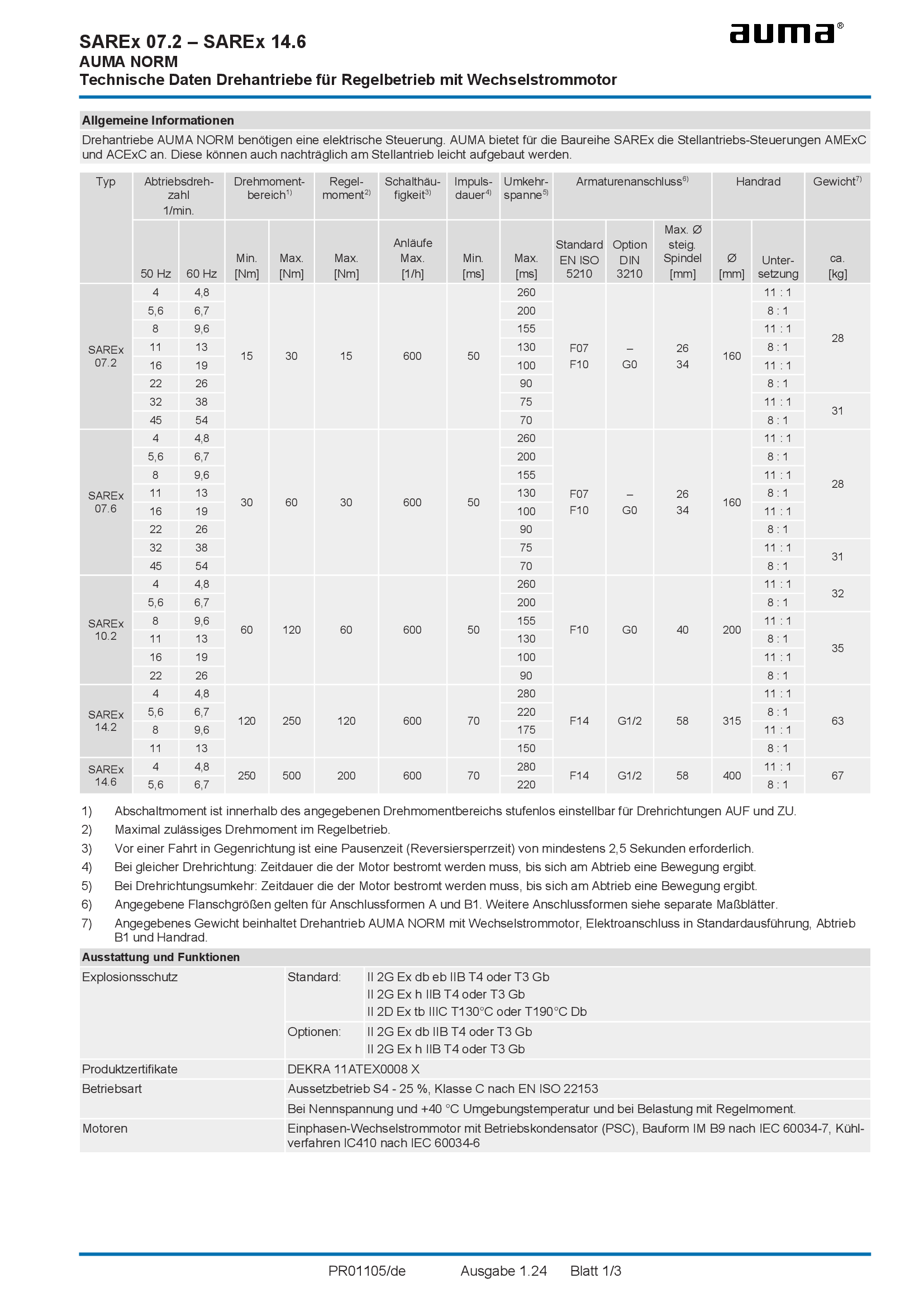
Multi-turn actuators SAREx 07.2 - 14.6, modulating duty, 1-phase AC
Technical data
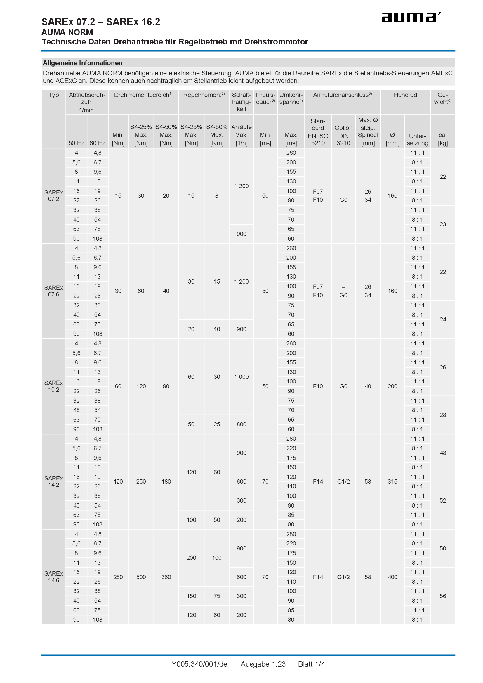
Multi-turn actuators SAREx 07.2 - 16.2, modulating duty, 3-phase AC
Technical data
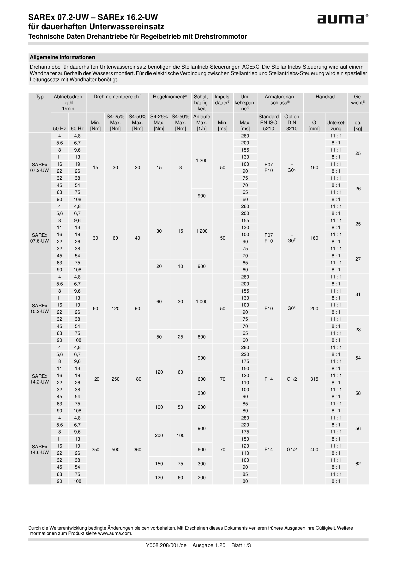
Multi-turn actuators SAREx 07.2-UW - SAREx 16.2-UW, modulatingn duty, 3-phase AC, for continuous underwater use
Technical data
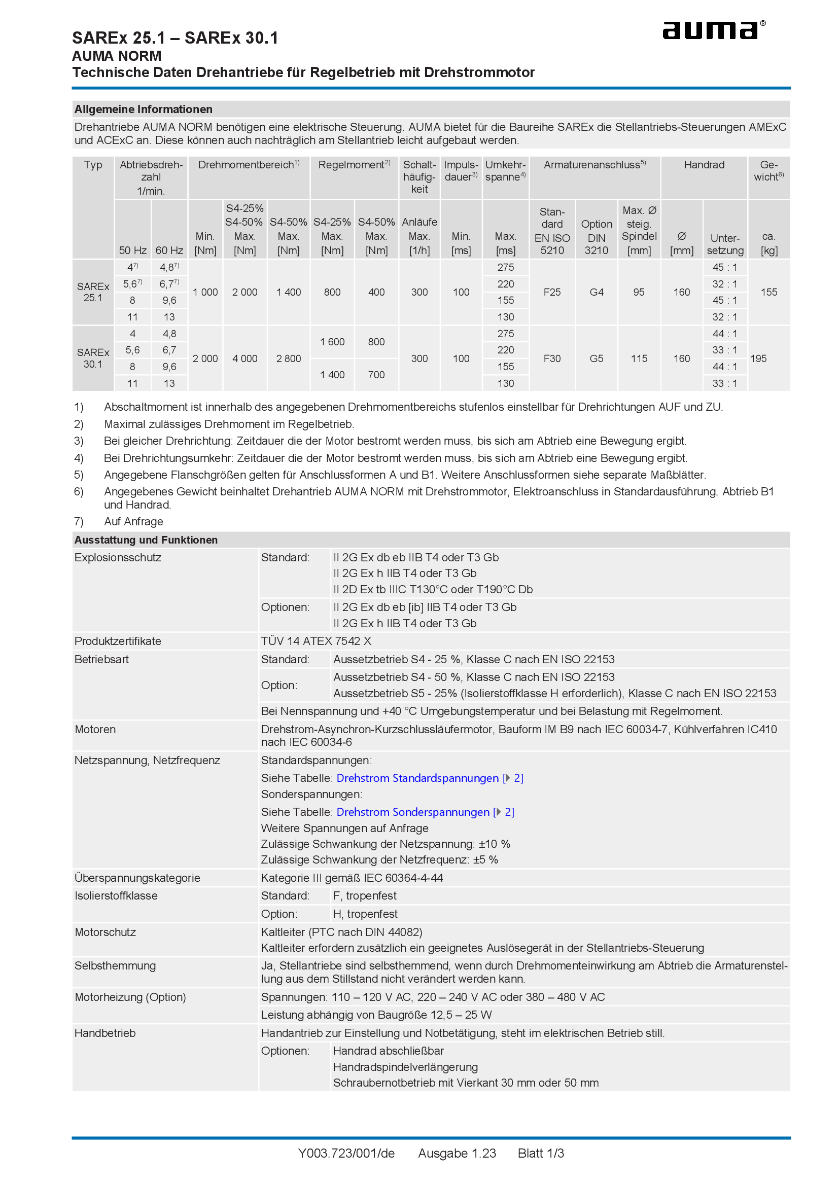
Multi-turn actuators SAREx 25.1 - 30.1, modulating duty, 3-phase AC
Technical data
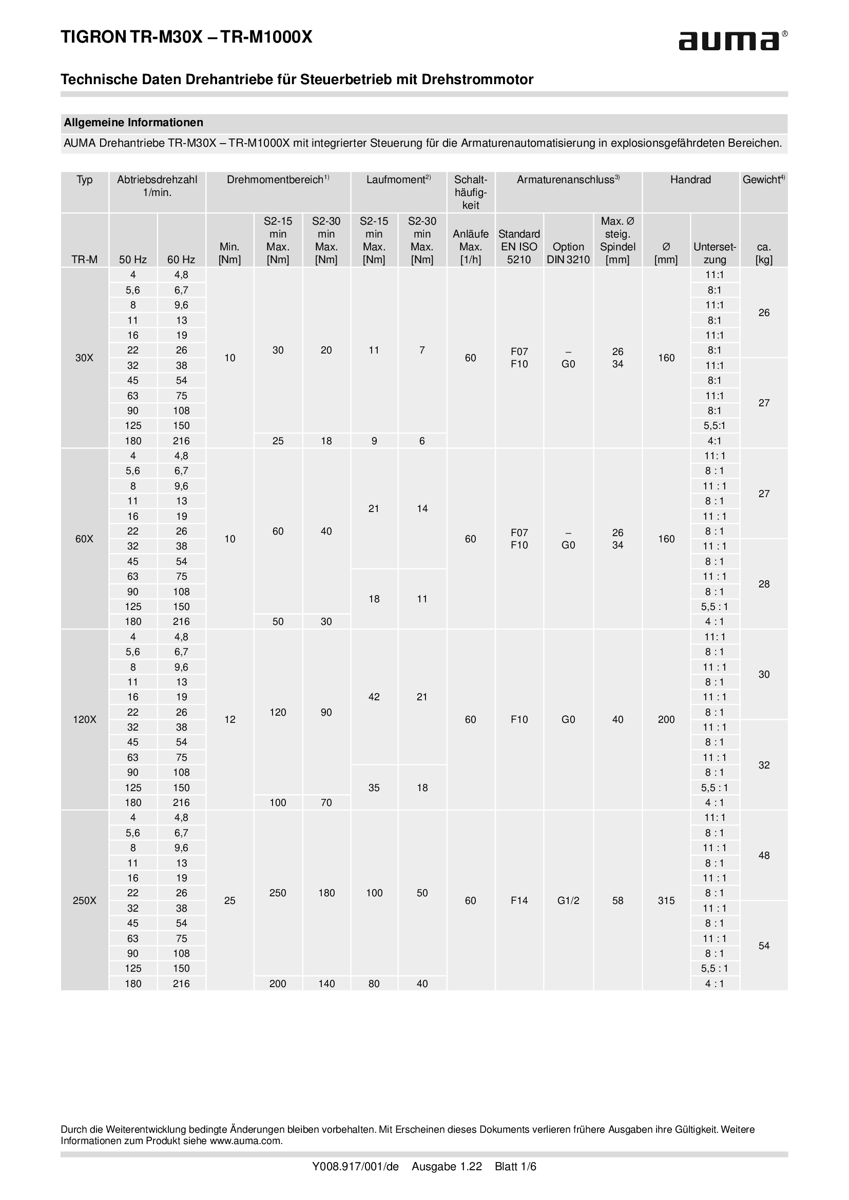
Multi-turn actuators TR-M30X - M1000X, open-close duty, 3-phase AC
Technical data
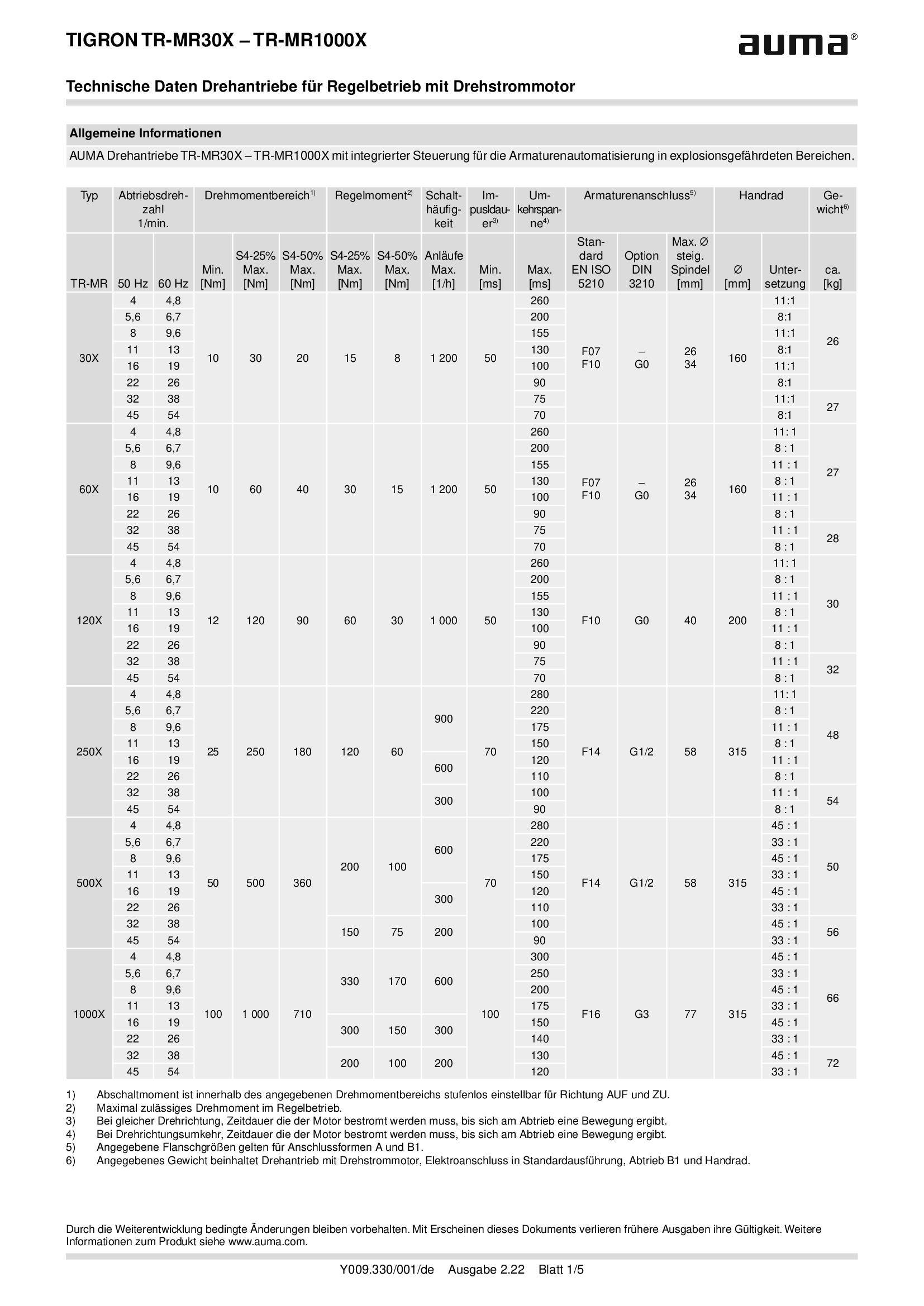
Multi-turn actuators TR-MR30X - MR1000X, modulating-duty, 3-phase AC
Technical data
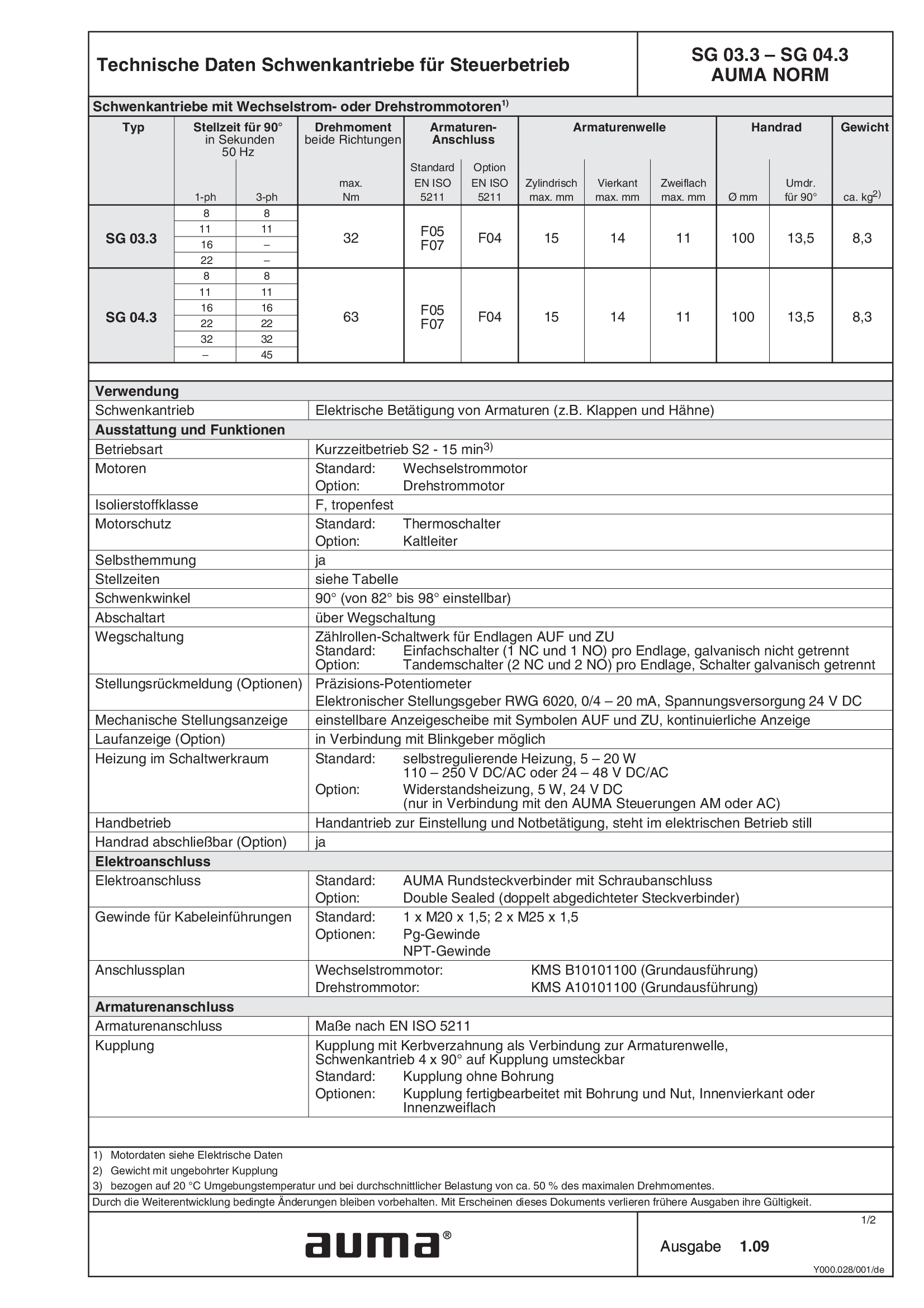
Part-turn actuators SG 03.3 - 04.3, open-close duty, 1-phase AC, 3-phase
Technical data
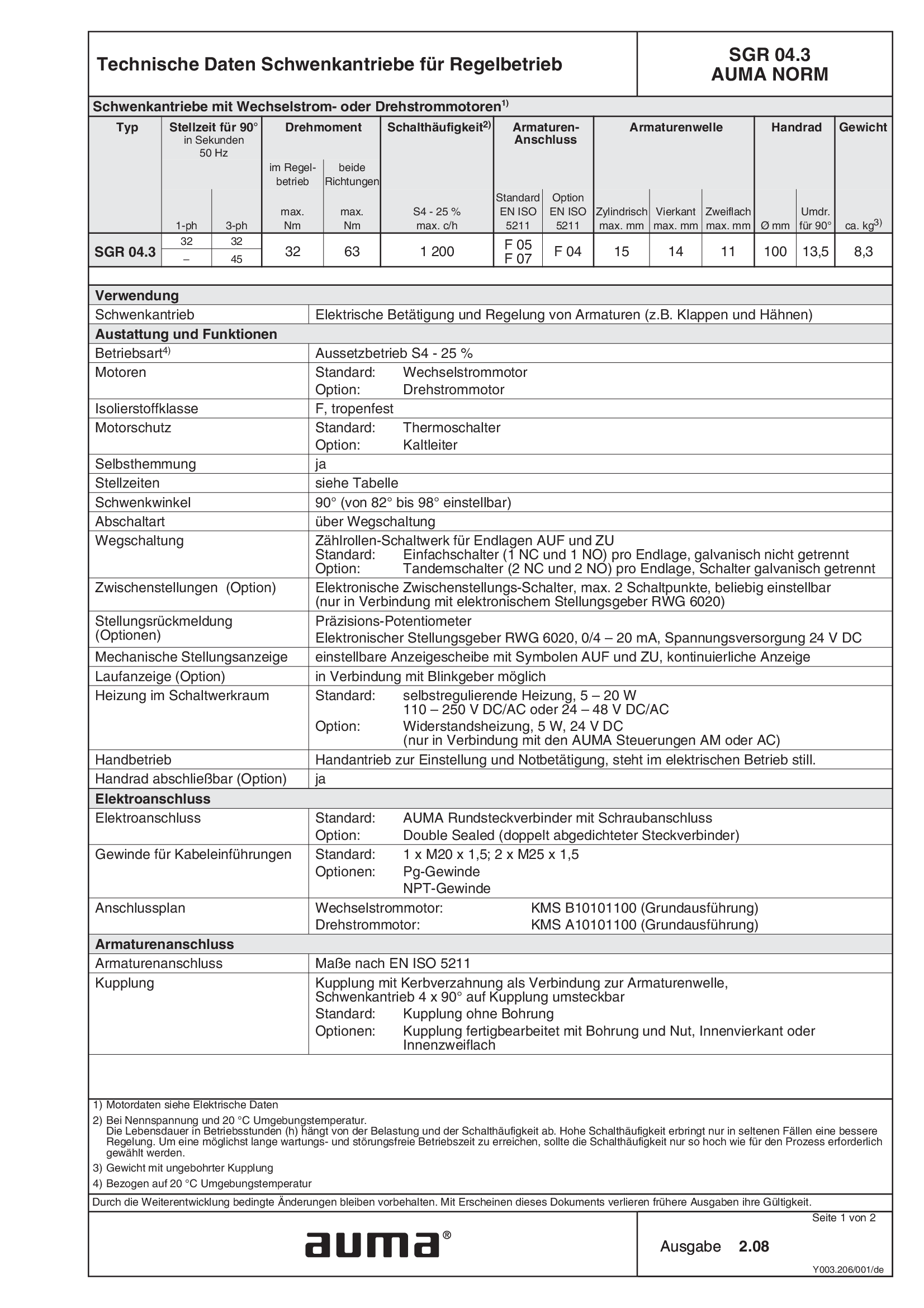
Part-turn actuators SGR 04.3, modulating duty, 1-phase AC, 3-phase
Technical data
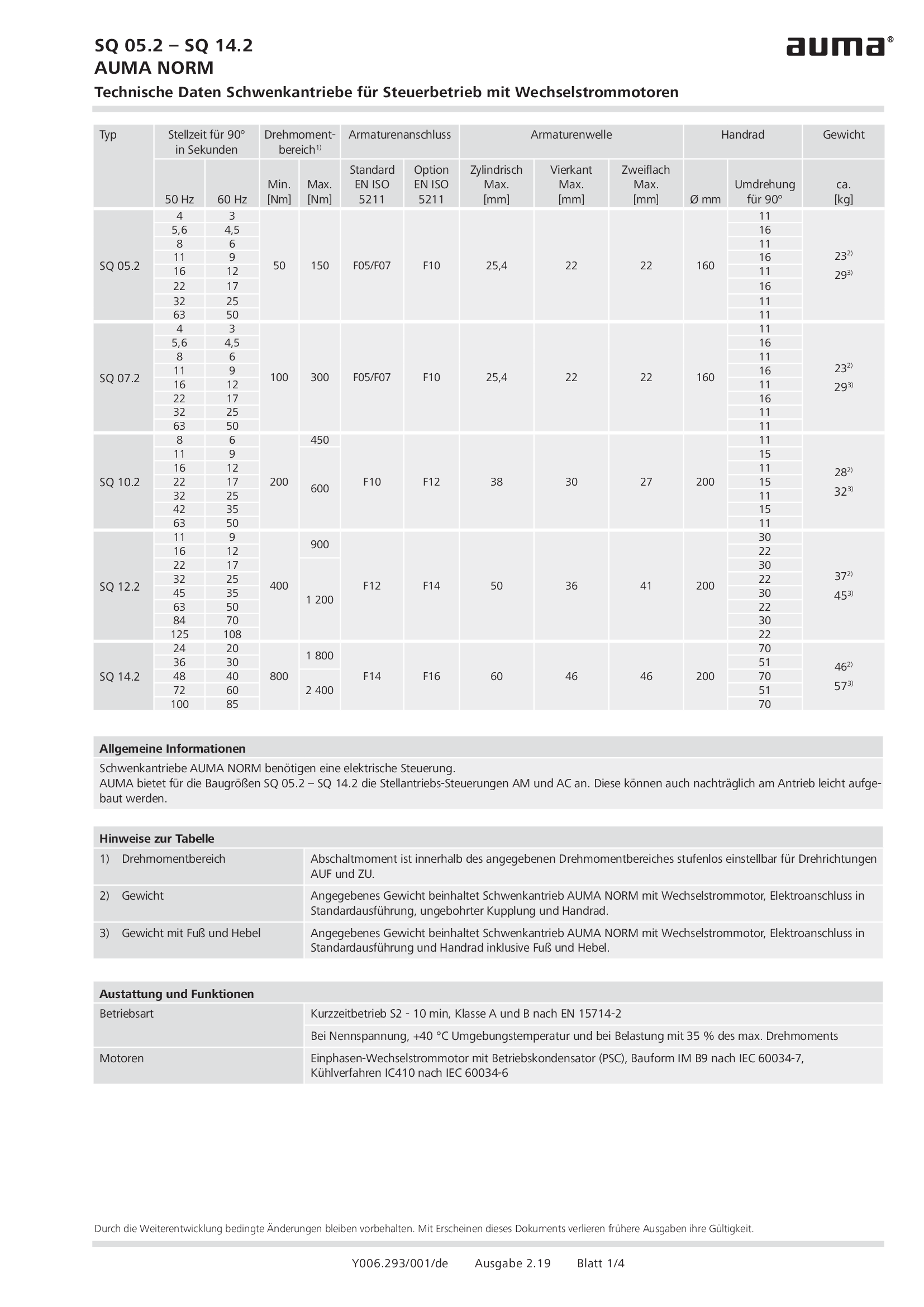
Part-turn actuators SQ 05.2 - 14.2, open-close duty, 1-phase AC
Technical data
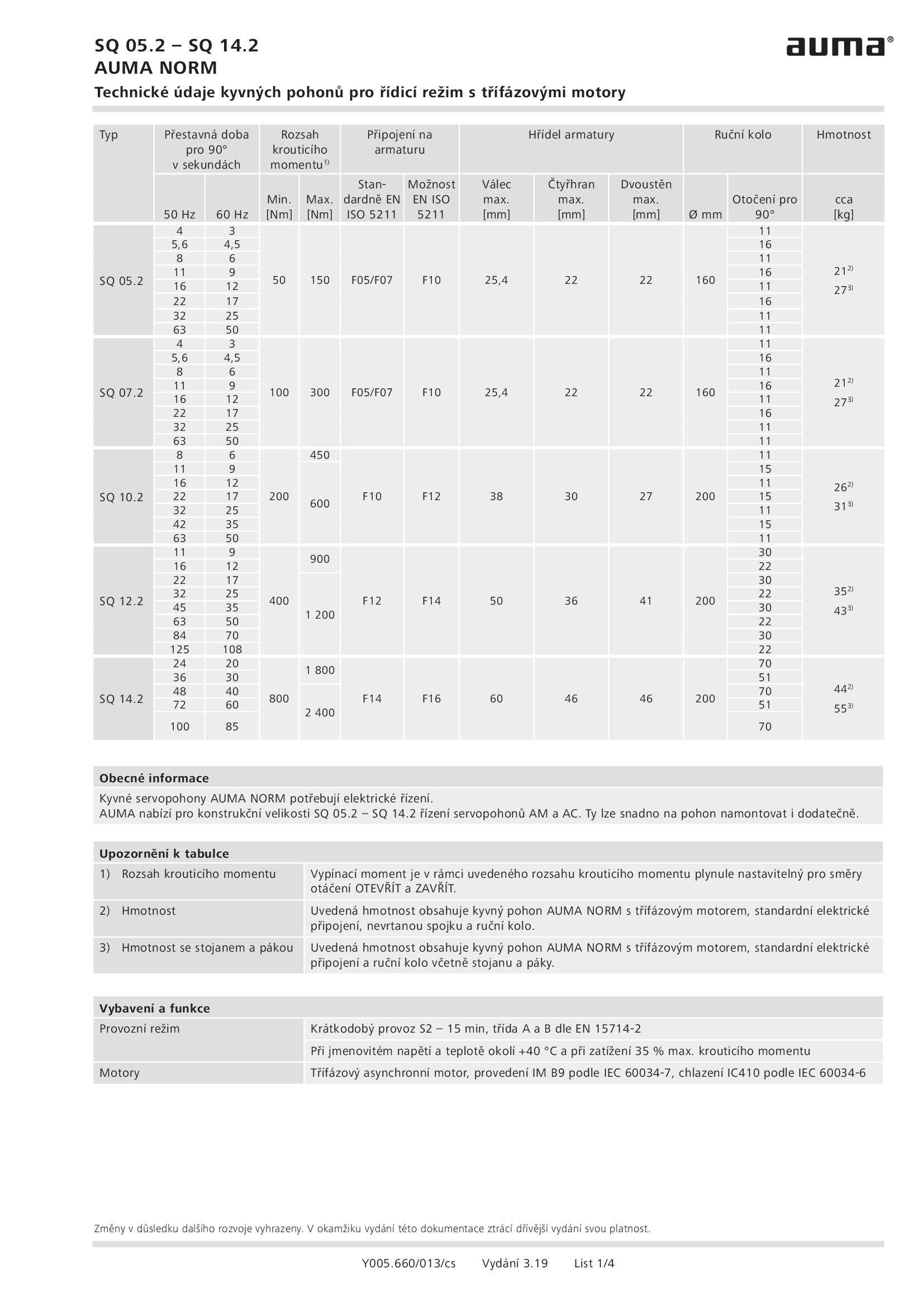
Part-turn actuators SQ 05.2 - 14.2, open-close duty, 3-phase AC
Technical data
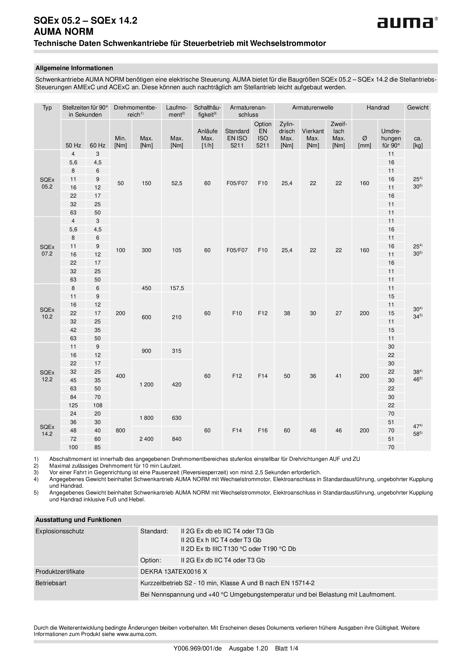
Part-turn actuators SQEx 05.2 - 14.2, open-close duty, 1-phase AC
Technical data

Part-turn actuators SQEx 05.2 - 14.2, open-close duty, 3-phase AC
Technical data

Part-turn actuators SQR 05.2 - 14.2, modulating duty, 1-phase AC
Technical data
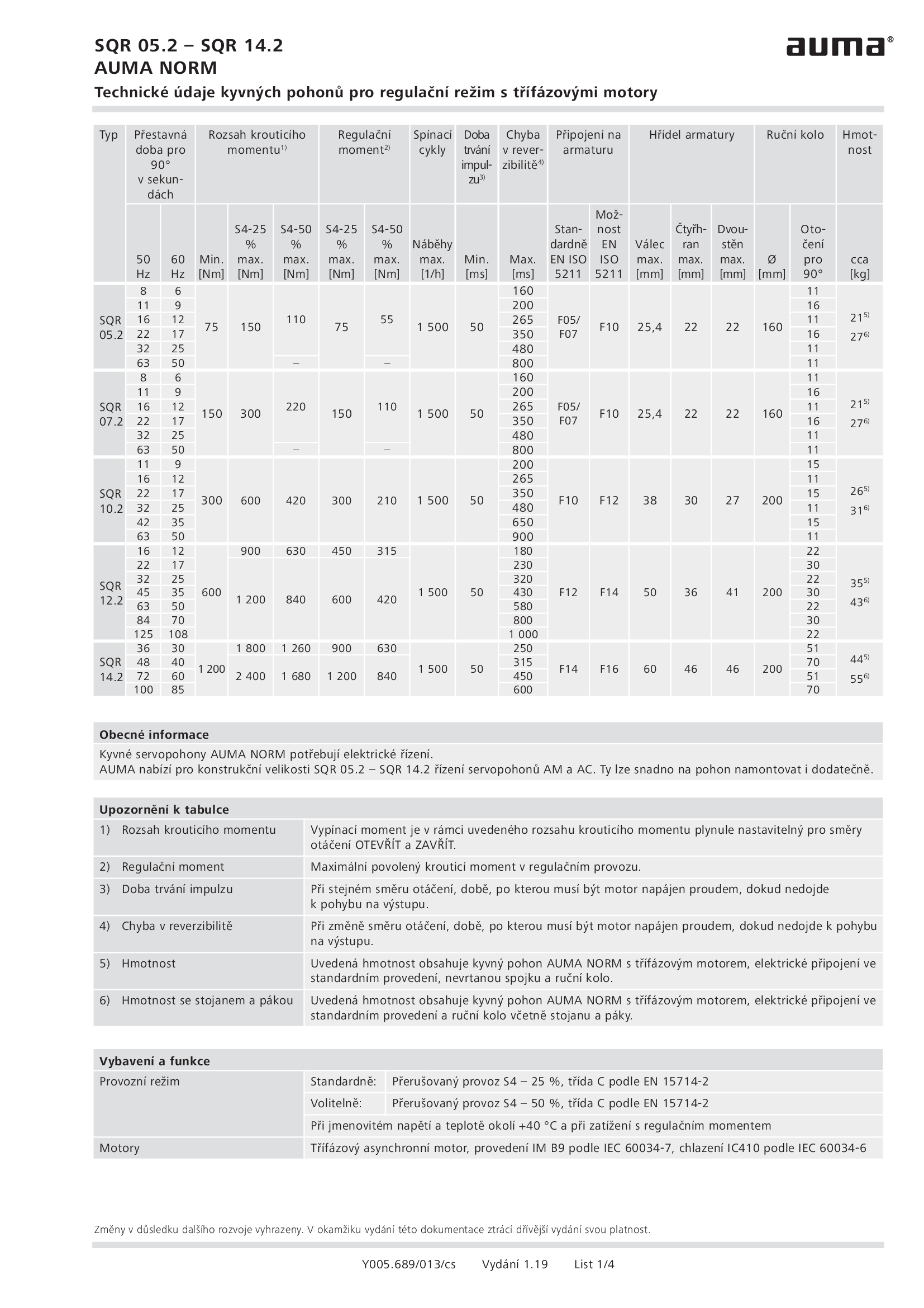
Part-turn actuators SQR 05.2 - 14.2, modulating duty, 3-phase AC
Technical data

Part-turn actuators SQREx 05.2 - 14.2, modulating duty, 1-phase AC
Technical data
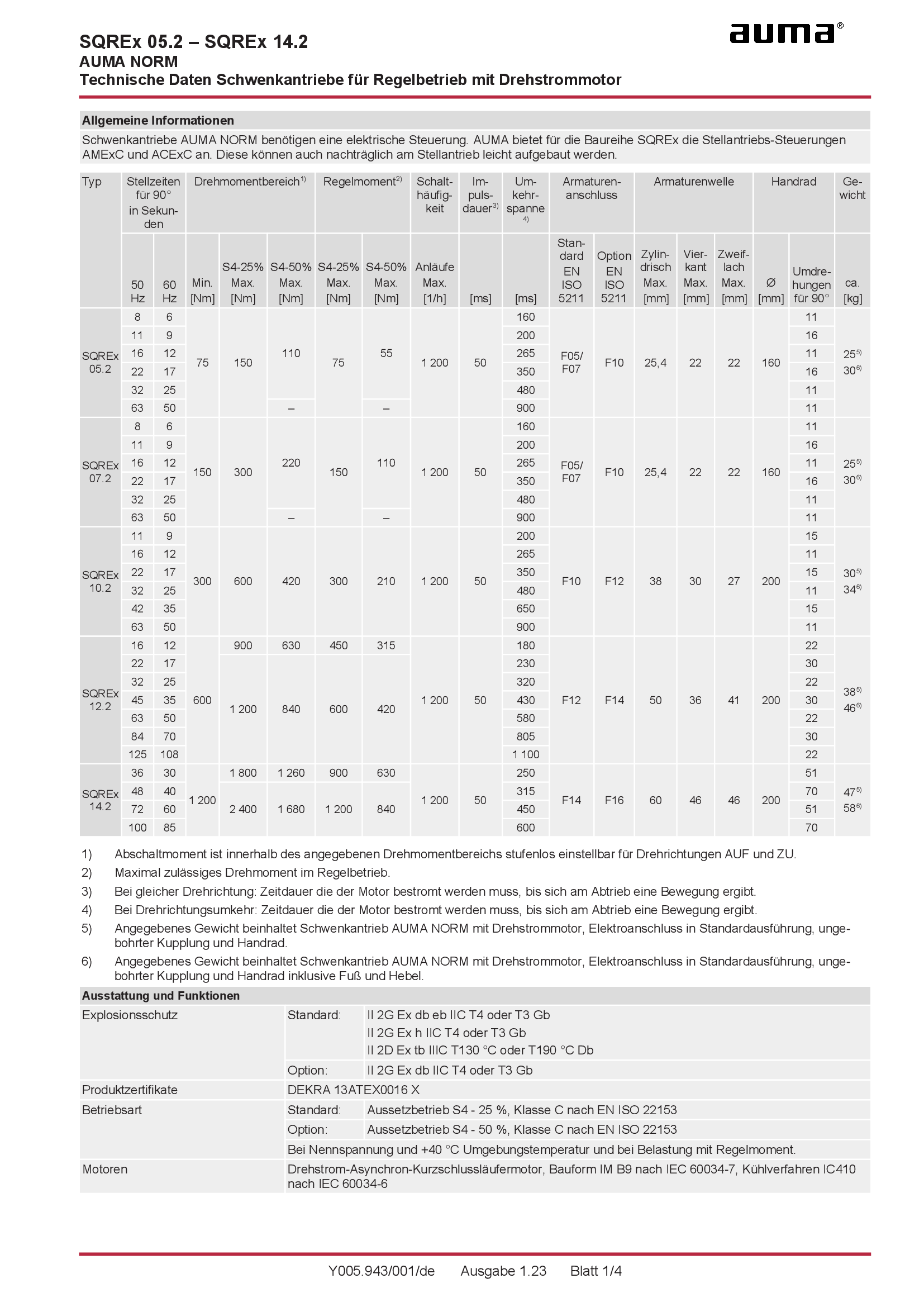
Part-turn actuators SQREx 05.2 - 14.2, modulating duty, 3-phase AC
Technical data

Part-turn actuators SQREx 05.2 - 14.2, modulating duty, 3-phase AC
Technical data
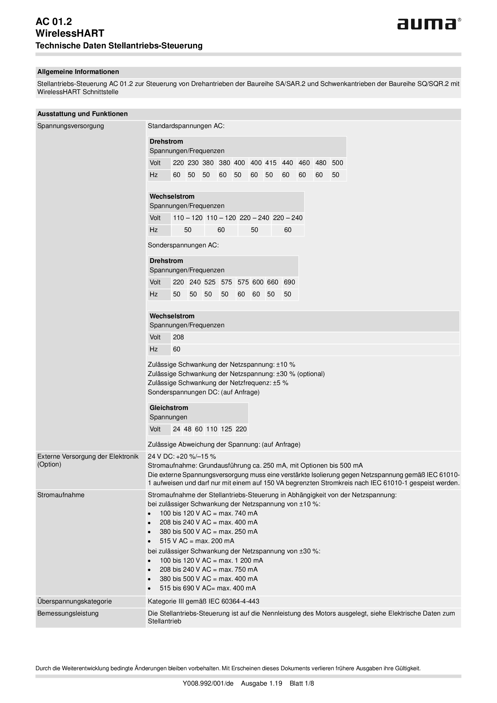
Stellantriebs-Steuerung AUMATIC AC 01.2, WirelessHART
Technical data
Technical description
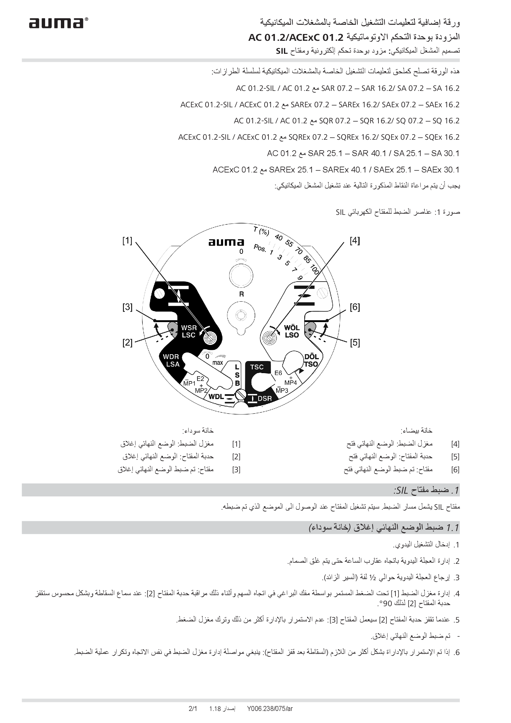
Supplement AUMATIC AC 01.2/ACExC 01.2, version actuators: with elektronic control unit (MWG) and SIL limit switching
Technical description
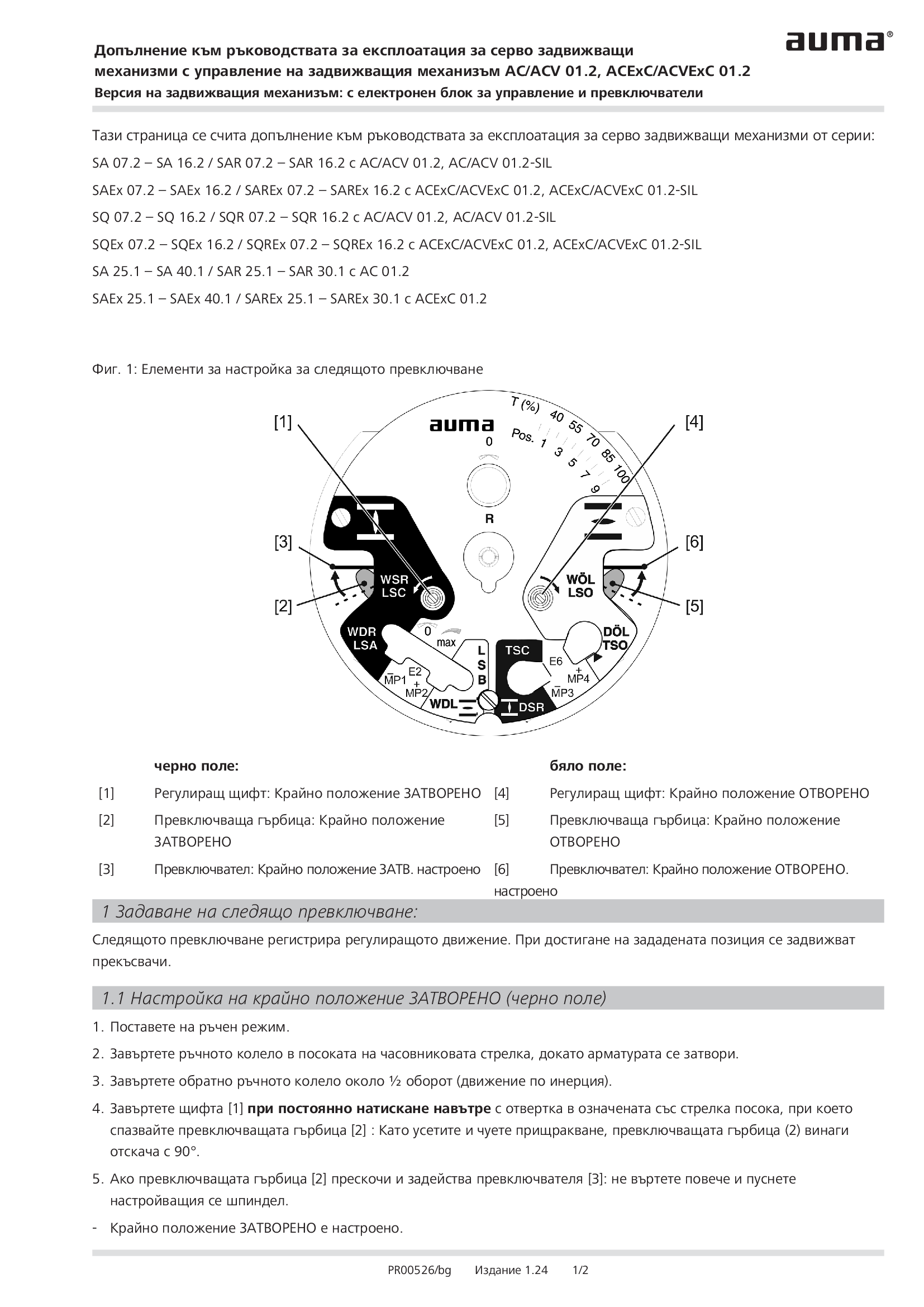
Supplement AUMATIC AC 01.2/ACExC 01.2, version actuators: with elektronic control unit (MWG) and limit switching
Technical description
Wiring diagram

A1: AUMATIC AC 01.2 position feedback signal 0/4 - 20 mA (potentiometer in actuator), basic version, reversing contactors OPEN, STOP, CLOSE, EMERGENCY (24 V DC), 6 programmable output contacts, AUMA power class A1 - A3
Wiring diagram

A1N: AUMATIC AC 01.2 position/torque feedback signal 0/4 - 20 mA (MWG in actuator), reversing contactors OPEN, STOP, CLOSE, EMERGENCY (24 V DC), 6 programmable output contacts, AUMA power class A1 - A3
Wiring diagram

A2: AUMATIC AC 01.2 positioner and postition feedback signal 0/4 - 20 mA (potentiometer in actuator), reversing contactors OPEN, STOP, CLOSE, EMERGENCY, MODE (24 V DC), 6 programmable output contacts, AUMA power class A1 - A3
Wiring diagram

A2DP: AUMATIC AC 01.2 position feedback (potentiometer in actuator), basic version, reversing contactors, Profibus, AUMA power class A1 - A3
Wiring diagram

A2ENIP: AUMATIC AC 01.2 position feedback (potentiometer in actuator), basic version, reversing contactors, Ethernet/IP, AUMA power class A3 - A3
Wiring diagram

A2FF: AUMATIC AC 01.2 position feedback (potentiometer in actuator), basic version, Reversing contactors, Foundation Fieldbus FF, AUMA power classes A1 – A3
Wiring diagram

A2HRT: AUMATIC AC 01.2 position feedback (potentiometer in actuator), basic version, Reversing contactors, HART actuatorAUMA power classes A1 – A3
Wiring diagram

A2HRTCO: AUMATIC AC 01.2 position feedback (potentiometer in actuator), basic version, Reversing contactors, HART Current Output, AUMA power classes A1 – A3
Wiring diagram

A2MB: AUMATIC AC 01.2 position feedback (potentiometer in actuator), basic version, reversing contactors, Modbus RTU, AUMA power class A1 - A3
Wiring diagram

A2MBTCP: AUMATIC AC 01.2 position feedback (potentiometer in actuator), basic version, Reversing contactors, Modbus TCP/IP, AUMA power classes A1 – A3
Wiring diagram

A2MBTCP: AUMATIC AC 01.2 position/torque feedback (MWG in actuator), Reversing contactors, Modbus TCP/IP, AUMA power classes A1 – A3
Wiring diagram

A2N: AUMATIC AC 01.2 positioner and position/torque feedback signal 0/4 - 20 mA (MWG in actuator), , reversing contactors OPEN, STOP, CLOSE, EMERGENCY, MODE (24 V DC), 6 programmable output contacts, AUMA power class A1 - A3
Wiring diagram

A2NDP: AUMATIC AC 01.2 position/torque feedback (MWG in actuator), reversing contactors, Profibus, AUMA power class A1 - A3
Wiring diagram

A2NENIP: AUMATIC AC 01.2, position/torque feedback (MWG in actuator, reversing contactors, Ethernet/IP, AUMA power class A1 - A 3
Wiring diagram

A2NFF: AUMATIC AC 01.2 position/torque feedback (MWG in actuator), Reversing contactors, Foundation Fieldbus FF, AUMA power classes A1 – A3
Wiring diagram

A2NHRT: AUMATIC AC 01.2 position/torque feedback (MWG in actuator), Reversing contactors, HART actuator, AUMA power classes A1 – A3
Wiring diagram

A2NHRTCO: AUMATIC AC 01.2 position/torque feedback (MWG in actuator), Reversing contactors, HART Current Output, AUMA power classes A1 – A3
Wiring diagram

A2NMB: AUMATIC AC 01.2 position/torque feedback (MWG in actuator), reversing contactors, Modbus RTU, AUMA power class A1 - A3
Wiring diagram

A3: AUMATIC AC 01.2 positioner and position feedback signal 0/4 - 20 mA (potentiometer in actuator), thyristors OPEN, STOP, CLOSE, EMERGENCY, MODE (24 V DC), 6 programmable output contacts, AUMA power class B1/B2
Wiring diagram

A3: AUMATIC AC 01.2 positioner and position feedback signal 0/4 - 20 mA (potentiometer in actuator), thyristors OPEN, STOP, CLOSE, EMERGENCY, MODE (24 V DC), 6 programmable output contacts, AUMA power class B3
Wiring diagram

A3DP: AUMATIC AC 01.2 position feedback (potentiometer in actuator), thyristors, Profibus, AUMA power class B1/B2
Wiring diagram

A3DP: AUMATIC AC 01.2 position feedback (potentiometer in actuator), thyristors, Profibus, AUMA power class B2
Wiring diagram

A3ENIP: AUATIC AC 01.2 postition feedback (potentiometer in actuator), Thyristors, EtherNet/IP, AUMA power class B1/B2
Wiring diagram

A3ENIP: AUATIC AC 01.2 postition feedback (potentiometer in actuator), Thyristors, EtherNet/IP, AUMA power class B3
Wiring diagram

A3FF: AUMATIC AC 01.2 position feedback (potentiometer in actuator), Thyristors, Foundation Fieldbus FF, AUMA power class B1/B2
Wiring diagram

A3FF: AUMATIC AC 01.2 position feedback (potentiometer in actuator), Thyristors, Foundation Fieldbus FF, AUMA power class B3
Wiring diagram

A3HRT: AUMATIC AC 01.2 position feedback (potentiometer in actuator), Thyristors, HART actuator, AUMA power class B1/B2
Wiring diagram

A3HRT: AUMATIC AC 01.2 position feedback (potentiometer in actuator), Thyristors, HART actuator, AUMA power class B3
Wiring diagram

A3HRTCO: AUMATIC AC 01.2 position feedback (potentiometer in actuator), Thyristors, HART Current Output, AUMA power class B1/B2
Wiring diagram

A3HRTCO: AUMATIC AC 01.2 position feedback (potentiometer in actuator), Thyristors, HART Current Output, AUMA power class B3
Wiring diagram

A3MB: AUMATIC AC 01.2 position feedback (potentiometer in actuator), thyristors, Modbus, AUMA power class B1/B2
Wiring diagram

A3MB: AUMATIC AC 01.2 position feedback (potentiometer in actuator), thyristors, Modbus, AUMA power class B3
Wiring diagram

A3MBTCP: AUMATIC AC 01.2 position feedback (potentiometer in actuator), Thyristors, Modbus TCP/IP, AUMA power class B1/B2
Wiring diagram

A3MBTCP: AUMATIC AC 01.2 position feedback (potentiometer in actuator), Thyristors, Modbus TCP/IP, AUMA power class B3
Wiring diagram

A3N: AUMATIC AC 01.2 positioner and position/torque feedback signal 0/4 - 20 mA (MWG in actuator), thyristors OPEN, STOP, CLOSE, EMERGENCY, MODE (24 V DC), 6 programmable output contacts, AUMA power class B1/B2
Wiring diagram

A3N: AUMATIC AC 01.2 positioner and position/torque feedback signal 0/4 - 20 mA (MWG in actuator), thyristors OPEN, STOP, CLOSE, EMERGENCY, MODE (24 V DC), 6 programmable output contacts, AUMA power class B3
Wiring diagram

A3NDP: AUMATIC AC 01.2 position/torque feedback (MWG in actuator), thyristors, Profibus, AUMA power class B1/B2
Wiring diagram

A3NDP: AUMATIC AC 01.2 position/torque feedback (MWG in actuator), thyristors, Profibus, AUMA power class B3
Wiring diagram

A3NENIP: AUMATIC AC 01.2 position/torque feedback (MWG in actuator), Thyristors, Ethernet/IP, AUMA power class B1/B2
Wiring diagram

A3NENIP: AUMATIC AC 01.2 position/torque feedback (MWG in actuator), Thyristors, Ethernet/IP, AUMA power class B3
Wiring diagram

A3NFF: AUMATIC AC 01.2 position/torque feedback (MWG in actuator), Thyristors, Foundation Fieldbus FF, AUMA power class B1/B2
Wiring diagram

A3NFF: AUMATIC AC 01.2 position/torque feedback (MWG in actuator), Thyristors, Foundation Fieldbus FF, AUMA power class B3
Wiring diagram

A3NHRT: AUMATIC AC 01.2 position/torque feedback (MWG in actuator), Thyristors, HART actuator, AUMA power class B1/B2
Wiring diagram

A3NHRT: AUMATIC AC 01.2 position/torque feedback (MWG in actuator), Thyristors, HART actuator, AUMA power class B3
Wiring diagram

A3NHRTCO: AUMATIC AC 01.2 position/torque feedback (MWG in actuator), Thyristors, HART actuator, AUMA power class B1/B2
Wiring diagram

A3NHRTCO: AUMATIC AC 01.2 position/torque feedback (MWG in actuator), Thyristors, HART actuator, AUMA power class B3
Wiring diagram

A3NMB: AUMATIC AC 01.2 position/torque feedback (MWG in actuator), thyristors, Modbus RTU, AUMA power class B1/B2
Wiring diagram

A3NMB: AUMATIC AC 01.2 position/torque feedback (MWG in actuator), thyristors, Modbus RTU, AUMA power class B3
Wiring diagram

A3NMBTCP: AUMATIC AC 01.2 position/torque feedback (MWG in actuator), Thyristors, Modbus TCP/IP, AUMA power class B1/B2
Wiring diagram

A3NMBTCP: AUMATIC AC 01.2 position/torque feedback (MWG in actuator), Thyristors, Modbus TCP/IP, AUMA power class B3
Wiring diagram

A3NPN: AUMATIC AC 01.2, position/torque feedback (MWG in actuator), Thyristors, Profinet, AUMA power class B1/B2
Wiring diagram

A3NPN: AUMATIC AC 01.2, position/torque feedback (MWG in actuator), Thyristors, Profinet, AUMA power class B3
Wiring diagram

A3PN: AUMATIC AC 01.2 position feedback (potentiometer in actuator), Thyristors, Profinet, AUMA power class B1/B2
Wiring diagram

A3PN: AUMATIC AC 01.2 position feedback (potentiometer in actuator), Thyristors, Profinet, AUMA power class B3
Wiring diagram

A4DP: AUMATIC AC 01.2 positioner and position feedback signal 0/4 - 20 mA (potentiometer in actuator),basic version, reversing contactors MODE, CLOSE, OPEN, STOP, EMERGENCY, I/O (24 V DC), Profibus DP, AUMA power class A1 - A3
Wiring diagram

A4ENIP: AUMATIC AC 01.2 positioner and position feedback signal 0/4 - 20 mA (potentiometer in actuator), basic version, reversing contactors MODE, CLOSE, OPEN, STOP, EMERGENCY, I/O (24 V DC), 6 programmable output contacts Ethernet/IP, AUMA power class
Wiring diagram

A4FF: AUMATIC AC 01.2 positioner and position feedback signal 0/4 – 20 mA (potentiometer in actuator), basic version, Reversing contactors MODE, CLOSE, OPEN, STOP, EMERGENCY, I/O (24V DC), 6 programmable output contacts, FF, AUMA power classes A1-A3
Wiring diagram

A4HRT: AUMATIC AC 01.2 positioner and position feedback signal 0/4-20mA (potentiometer in actuator), basic version, Reversing contactors MODE, CLOSE, OPEN, STOP, EMERGENCY, I/O (24V DC), 6 programmable output contacts, HART, AUMA power classes A1 – A3
Wiring diagram

A4HRT: AUMATIC AC 01.2 positioner and position feedback signal 0/4-20mA (potentiometer within actuator), basic version, Reversing contactors MODE, CLOSE, OPEN, STOP, EMERGENCY, I/O (24V DC), 6 programmable output contacts, HART AUMA power classes A1 – A3
Wiring diagram

A4HRTCO: AUMATIC AC 01.2 positioner and position feedback signal 0/4-20mA (potentiometer in actuator), basic version, Reversing contactors MODE, CLOSE, OPEN, STOP, EMERGENCY, I/O (24V DC), 6 programmable output contacts, HART, AUMA power classes A1-A3
Wiring diagram

A4MB: AUMATIC AC 01.2 positioner and position feedback signal 0/4 - 20 mA (potentiometer in actuator), basic version, reversing contactors MODE, CLOSE, OPEN, STOP, EMERGENCY, I/O (24 V DC), 6programmable output contacts, Modbus RTU, power class A1 - A3
Wiring diagram

A4N: AUMATIC AC 01.2 process controller and position/torque feedback signal 0/4 - 20 mA (MWG in actuator), thyristors CLOSE, OPEN, STOP, EMERGENCY, MODE (24 V DC), 6 programmable output contacts, AUMA power class B1/B2
Wiring diagram

A4NDP: AUMATIC AC 01.2 positioner and position/torque feedback signal 0/4 - 20 mA (MWG in actuator), reversing contactors MODE, CLOSE, OPEN, STOP, EMERGENCY, I/O (24 V DC), 6 programmable output contacts, Profibus DP, AUMA power class A1 - A3
Wiring diagram

A4NENIP: AUMATIC AC 01.2 positioner and position/torque feedbacksignal 0/4 - 20 mA (MWG in actuator), reversing contactors MODE, CLOSE, OPEN, STOP, EMERGENCY, I/O (24 v DC), 6 programmable output contacts, EtherNet/IP, AUMA power class A1 - A3
Wiring diagram

A4NHRT: AUMATIC AC 01.2 positioner and position/torque feedback signal 0/4 – 20 mA (MWG in actuator), Reversing contactors MODE, CLOSE, OPEN, STOP, EMERGENCY, I/O (24 V DC), 6 programmable output contacts, HART, AUMA power classes A1 – A3
Wiring diagram

A4NHRTCO: AUMATIC AC 01.2 position/torque feedback (MWG in actuator), Reversing contactors MODE, CLOSE, OPEN, STOP, EMERGENCY, I/O (24 V DC), 6 programmable output contacts, HART current output, AUMA power classes A1 – A3
Wiring diagram

A4NMB: AUMATIC AC 01.2 positioner and position/torque feedback signal 0/4 - 20 mA (MWG in actuator), reversing contactors MODE, CLOSE, OPEN, STOP, EMERGENCY, I/O (24 V DC), 6 programmable output contacts, Modbus RTU, AUMA power class A1 - A3
Wiring diagram

A4NMBTCP: AUMATIC AC 01.2 positioner and position/torque feedback signal 0/4 – 20 mA (MWG in actuator), Reversing contactors MODE, CLOSE, OPEN, STOP, EMERGENCY, I/O (24 V DC), 6 programmable output contacts, Modbus RTU, AUMA power classes A1 – A3
Wiring diagram

A5DP: AUMATIC AC 01.2 positioner and position feedback signal 0/4 - 20 mA (potentiometer in actuator), thyristors MODE, CLOSE, OPEN, STOP, EMERGENCY, I/O (24 V DC), 6 programmable output contacts, Profibus DP, AUMA power class B1/B2
Wiring diagram

A5DP: AUMATIC AC 01.2 positioner and position feedback signal 0/4 - 20 mA (potentiometer in actuator), thyristors MODE, CLOSE, OPEN, STOP, EMERGENCY, I/O (24 V DC), 6 programmable output contacts, Profibus DP, AUMA power class B3
Wiring diagram

A5ENIP: AUMATIC AC 01.2 positioner and position feedback signal 0/4 - 20 mA (potentiometer in actuator), Thyristors, MODE, CLOSE, OPEN, STOP, EMERGENCY, I/O (24 V DC), 6 programmable output contacts, EtherNet/IP, AUMA power class B1 / B2
Wiring diagram

A5ENIP: AUMATIC AC 01.2 positioner and position feedback signal 0/4 - 20 mA (potentiometer in actuator), Thyristors, MODE, CLOSE, OPEN, STOP, EMERGENCY, I/O (24 V DC), 6 programmable output contacts, EtherNet/IP, AUMA power class B3
Wiring diagram

A5FF: AUMATIC AC 01.2 positioner and position feedback signal 0/4 – 20 mA (potentiometer in actuator), Thyristors MODE, CLOSE, OPEN, STOP, EMERGENCY, I/O (24 V DC), 6 programmable output contacts, Foundation Fieldbus, AUMA power class B1/B2
Wiring diagram

A5FF: AUMATIC AC 01.2 positioner and position feedback signal 0/4 – 20 mA (potentiometer in actuator), Thyristors MODE, CLOSE, OPEN, STOP, EMERGENCY, I/O (24 V DC), 6 programmable output contacts, Foundation Fieldbus, AUMA power class B3
Wiring diagram

A5FF: AUMATIC AC 01.2 positioner and position feedback signal 0/4 – 20 mA (potentiometer in actuator), Thyristors MODE, CLOSE, OPEN, STOP, EMERGENCY, I/O (24 V DC), 6 programmable output contacts,´Foundation Fieldbus, AUMA power class B1/B2
Wiring diagram

A5HRT: AUMATIC AC 01.2 positioner and position feedback signal 0/4 – 20 mA (potentiometer in actuator), Thyristors MODE, CLOSE, OPEN, STOP, EMERGENCY, I/O (24 V DC), 6 programmable output contacts, HART, AUMA power class B1/B2
Wiring diagram

A5HRT: AUMATIC AC 01.2 positioner and position feedback signal 0/4 – 20 mA (potentiometer in actuator), Thyristors MODE, CLOSE, OPEN, STOP, EMERGENCY, I/O (24 V DC), 6 programmable output contacts, HART, AUMA power class B3
Wiring diagram

A5HRTCO: AUMATIC AC 01.2 position feedback (potentiometer in actuator), Thyristors MODE, CLOSE, OPEN, STOP, EMERGENCY, I/O (24 V DC), 6 programmable output contacts, HART Current Output, AUMA power class B1/B2
Wiring diagram

A5HRTCO: AUMATIC AC 01.2 position feedback (potentiometer in actuator), Thyristors MODE, CLOSE, OPEN, STOP, EMERGENCY, I/O (24 V DC), 6 programmable output contacts, HART Current Output, AUMA power class B3
Wiring diagram

A5MB: AUMATIC AC 01.2 positioner and position feedback signal 0/4 - 20 mA (potentiometer in actuator), thyristors MODE, CLOSE, OPEN, STOP, EMERGENCY, I/O (24 V DC), 6 prgrammable output contacts, Modbus RTU, AUMA power class B1/B2
Wiring diagram

A5MB: AUMATIC AC 01.2 positioner and position feedback signal 0/4 - 20 mA (potentiometer in actuator), thyristors MODE, CLOSE, OPEN, STOP, EMERGENCY, I/O (24 V DC), 6 prgrammable output contacts, Modbus RTU, AUMA power class B3
Wiring diagram

A5MBTCP: AUMATIC AC 01.2 positioner and position feedback signal 0/4 – 20 mA (potentiometer in actuator), Thyristors MODE, CLOSE, OPEN, STOP, EMERGENCY, I/O (24 V DC), 6 programmable output contacts, Modbus TCP/IP, AUMA power class B1/B2
Wiring diagram

A5MBTCP: AUMATIC AC 01.2 positioner and position feedback signal 0/4 – 20 mA (potentiometer in actuator), Thyristors MODE, CLOSE, OPEN, STOP, EMERGENCY, I/O (24 V DC), 6 programmable output contacts, Modbus TCP/IP, AUMA power class B3
Wiring diagram

A5N: AUMATIC AC 01.2 position/torque feedback signal 0/4 - 20 mA (MWG in actuator), reversing contactors CLOSE, OPEN, STOP, EMERGENCY, INTERLOCK CLOSE, INTERLOCK OPEN, 6 programmable output contacts, AUMA power class A1 - A3
Wiring diagram

A5NDP: AUMATIC AC 01.2 positioner and position/torque feedback signal 0/4 - 20 mA (MWG in actuator), thyristors MODE, CLOSE, OPEN, STOP, EMERGENCY, I/O (24 V DC), 6 programmable output contacts, Profibus DP, AUMA power class B1/B2
Wiring diagram

A5NDP: AUMATIC AC 01.2 positioner and position/torque feedback signal 0/4 - 20 mA (MWG in actuator), thyristors MODE, CLOSE, OPEN, STOP, EMERGENCY, I/O (24 V DC), 6 programmable output contacts, Profibus DP, AUMA power class B3
Wiring diagram

A5NENIP: AUMATIC AC 01.2 positioner and position/torque feedback signal 0/4 - 20 mA (WG in actuator), Thyristors MODE, CLOSE, OPEN, STOP, EMERGENCY, I/O (24 v DC), 6 programmable output contacts, EtherNet/IP, power class B1 / B2
Wiring diagram

A5NENIP: AUMATIC AC 01.2 positioner and position/torque feedback signal 0/4 - 20 mA (WG in actuator), Thyristors MODE, CLOSE, OPEN, STOP, EMERGENCY, I/O (24 v DC), 6 programmable output contacts, EtherNet/IP, power class B3
Wiring diagram

A5NFF: AUMATIC AC 01.2 positioner and position/torque feedback signal 0/4 – 20 mA (MWG in actuator), Thyristors MODE, CLOSE, OPEN, STOP, EMERGENCY, I/O (24 V DC), 6 programmable output contacts, Foundation Fieldbus FF, AUMA power class B1/B2
Wiring diagram

A5NFF: AUMATIC AC 01.2 positioner and position/torque feedback signal 0/4 – 20 mA (MWG in actuator), Thyristors MODE, CLOSE, OPEN, STOP, EMERGENCY, I/O (24 V DC), 6 programmable output contacts, Foundation Fieldbus FF, AUMA power class B3
Wiring diagram

A5NHRT: AUMATIC AC 01.2 positioner and position/torque feedback signal 0/4 – 20 mA (MWG in actuator), Thyristors MODE, CLOSE, OPEN, STOP, EMERGENCY, I/O (24 V DC), 6 programmable output contacts, HART, AUMA power class B1/B2
Wiring diagram

A5NHRT: AUMATIC AC 01.2 positioner and position/torque feedback signal 0/4 – 20 mA (MWG in actuator), Thyristors MODE, CLOSE, OPEN, STOP, EMERGENCY, I/O (24 V DC), 6 programmable output contacts, HART, AUMA power class B3
Wiring diagram

A5NHRTCO: AUMATIC AC 01.2 position/torque feedback (MWG in actuator), Thyristors MODE, CLOSE, OPEN, STOP, EMERGENCY, I/O (24 V DC), 6 programmable output contacts, HART Current Output, AUMA power class B1/B2
Wiring diagram

A5NHRTCO: AUMATIC AC 01.2 position/torque feedback (MWG in actuator), Thyristors MODE, CLOSE, OPEN, STOP, EMERGENCY, I/O (24 V DC), 6 programmable output contacts, HART Current Output, AUMA power class B3
Wiring diagram

A5NMB: AUMATIC AC 01.2 positioner and position/torque feedback signal 0/4 - 20 mA (MWG in actuator) thyristors MODE, CLOSE, OPEN, EMERGENCY, I/O (24 V DC), 6 programmable output contacts, Modbus RTU, AUMA power class B1/B2
Wiring diagram

A5NMB: AUMATIC AC 01.2 positioner and position/torque feedback signal 0/4 - 20 mA (MWG in actuator) thyristors MODE, CLOSE, OPEN, EMERGENCY, I/O (24 V DC), 6 programmable output contacts, Modbus RTU, AUMA power class B3
Wiring diagram

A5NMBTCP: AUMATIC AC 01.2 positioner and position/torque feedback signal 0/4 – 20 mA (MWG in actuator), Thyristors MODE, CLOSE, OPEN, STOP, EMERGENCY, I/O (24 V DC), 6 programmable output contacts, Modbus TCP/IP, AUMA power class B1/B2
Wiring diagram

A5NMBTCP: AUMATIC AC 01.2 positioner and position/torque feedback signal 0/4 – 20 mA (MWG in actuator), Thyristors MODE, CLOSE, OPEN, STOP, EMERGENCY, I/O (24 V DC), 6 programmable output contacts, Modbus TCP/IP, AUMA power class B3
Wiring diagram

A5NPN: AUMATIC AC 01.2 positioner and position/torque feedback signal 0/4 – 20 mA (MWG in actuator), Thyristors, Profinet, AUMA power class B1/B2
Wiring diagram

A5NPN: AUMATIC AC 01.2 positioner and position/torque feedback signal 0/4 – 20 mA (MWG in actuator), Thyristors, Profinet, AUMA power class B3
Wiring diagram

A5PN: AUMATIC AC 01.2 positioner and position feedback signal 0/4 – 20 mA (potentiometer in actuator), Thyristors, Profinet, AUMA power class B1/B2
Wiring diagram

A5PN: AUMATIC AC 01.2 positioner and position feedback signal 0/4 – 20 mA (potentiometer in actuator), Thyristors, Profinet, AUMA power class B3
Wiring diagram

AV2HRT: AUMATIC AC 01.2 position feedback (potentiometer in actuator), basic version, HART actuator, 1-ph; 220 V - 240 V
Wiring diagram

AV2HRT: AUMATIC AC 01.2 position feedback (potentiometer in actuator), basic version, HART actuator, 3-ph; 380 V - 480 V
Wiring diagram

AV2NHRT: AUMATIC AC 01.2 position/torque feedback (MWG in actuator), HART actuator, 3-ph; 380 V - 480 V
Wiring diagram
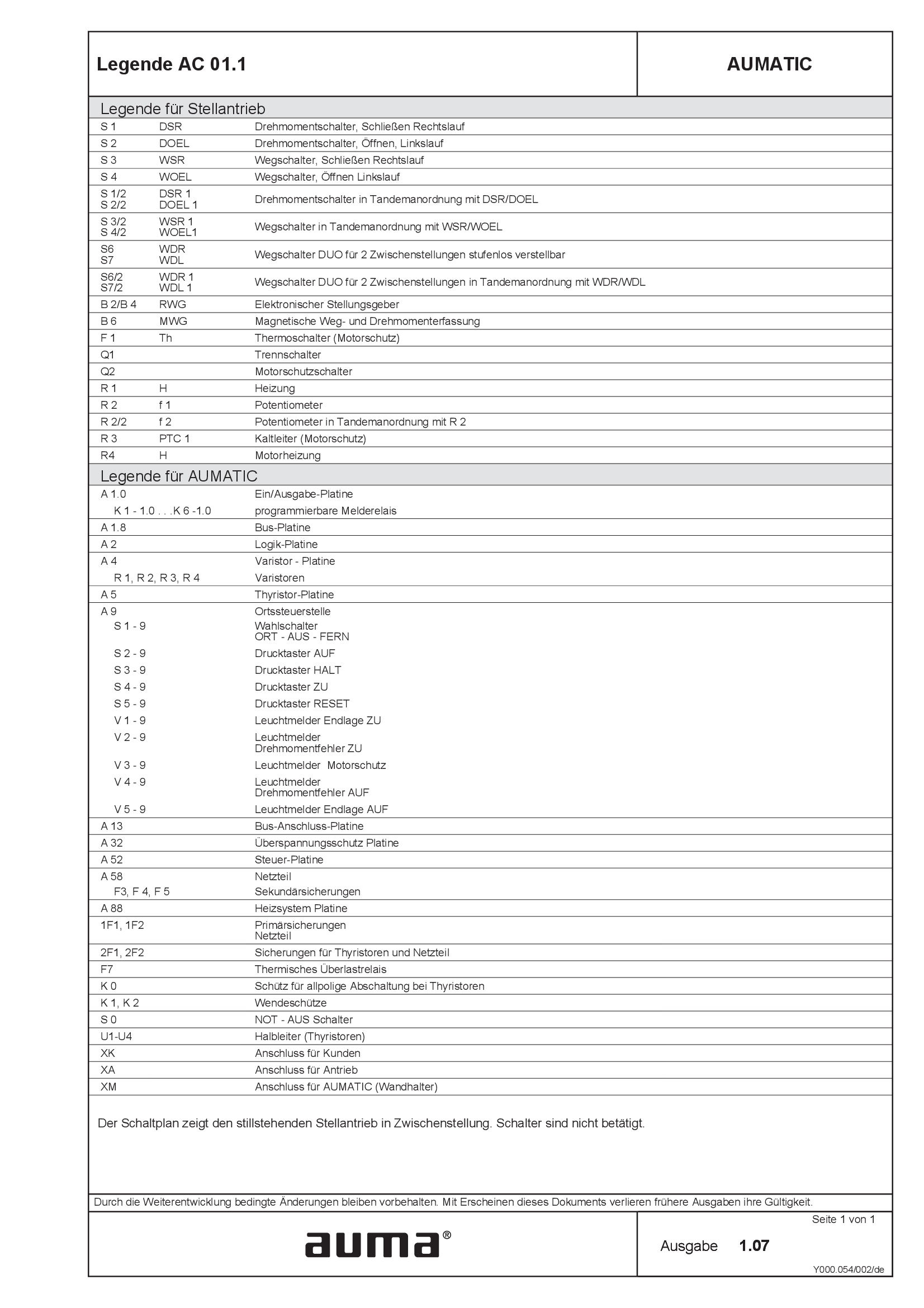
Legend AC 01.1
Wiring diagram
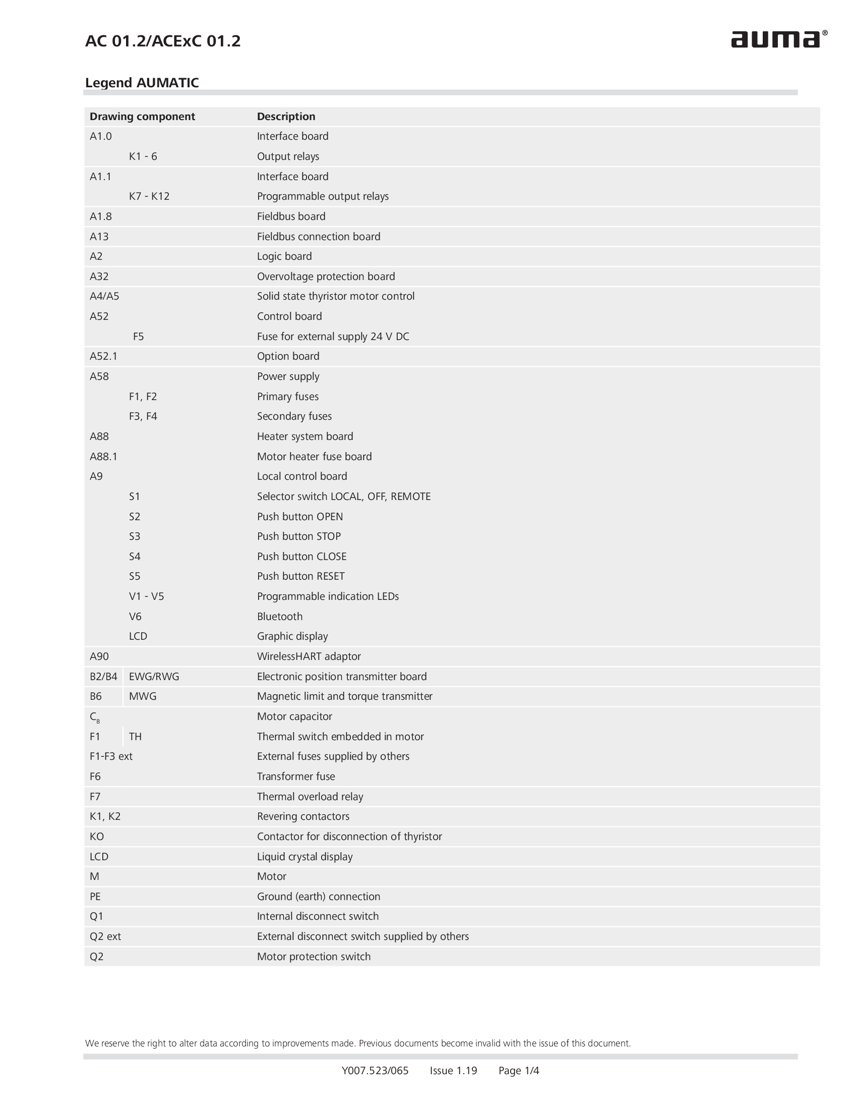
Legend AC 01.2/ACEx 01.2
Wiring diagram

Legend AC 01.2/ACEx 01.2, AC 01.2-SIL/ACExC 01.2-SIL
Wiring diagram
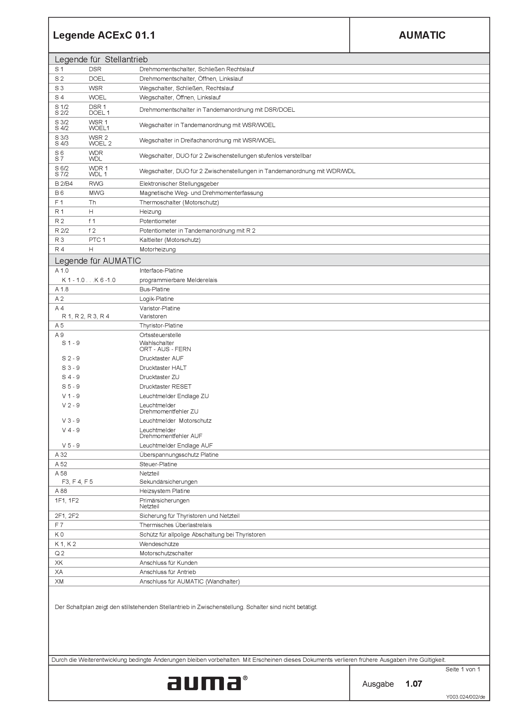
Legend ACExC01.1
Wiring diagram
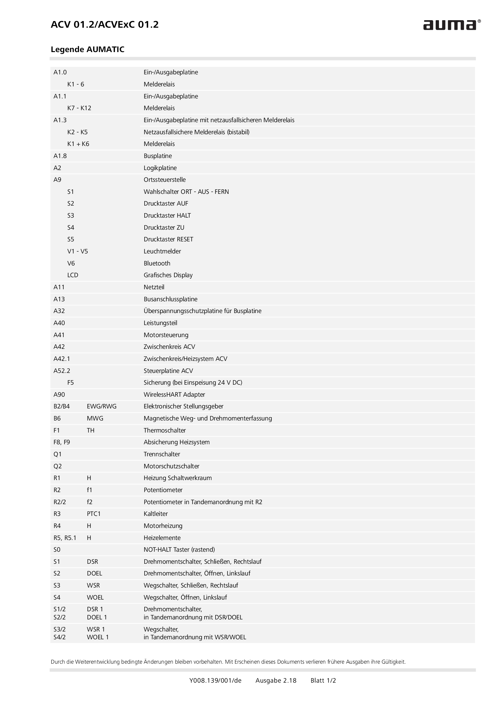
Legend ACV 01.2/ACVEx 01.2
Wiring diagram
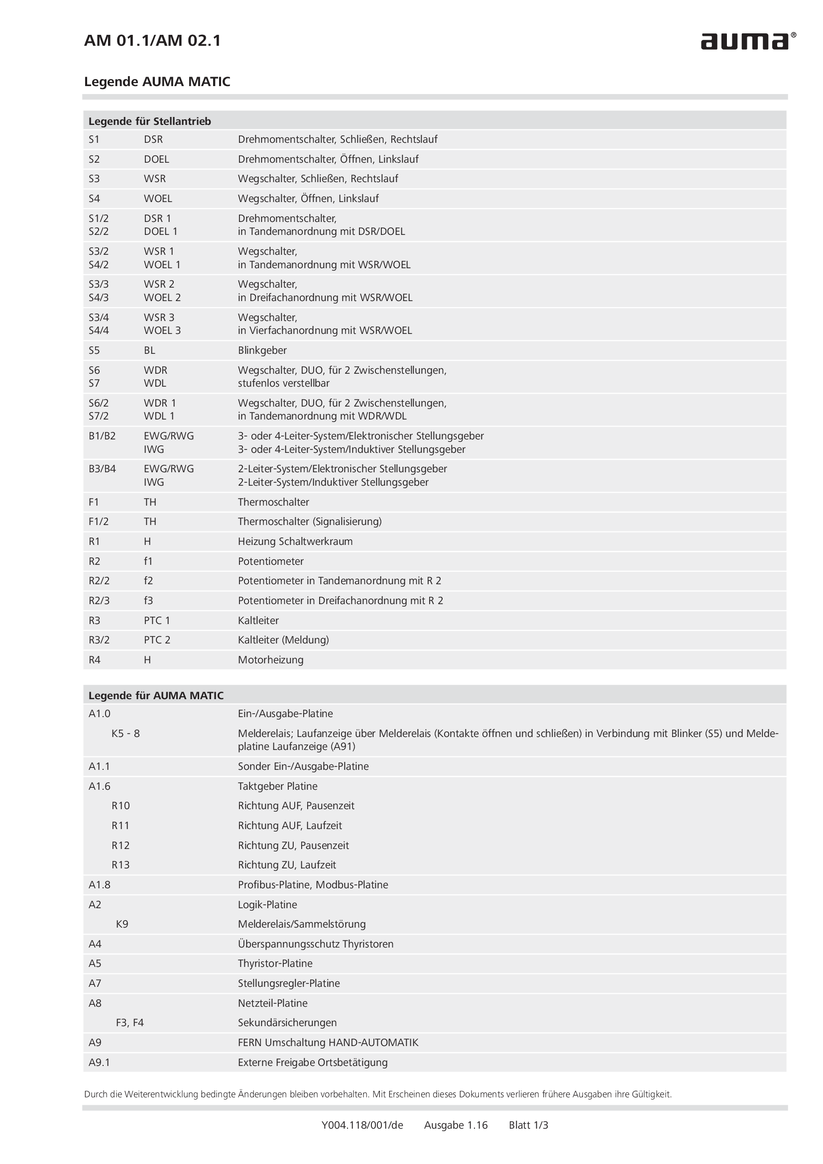
Legend AM 01.1/AM 02.1
Wiring diagram
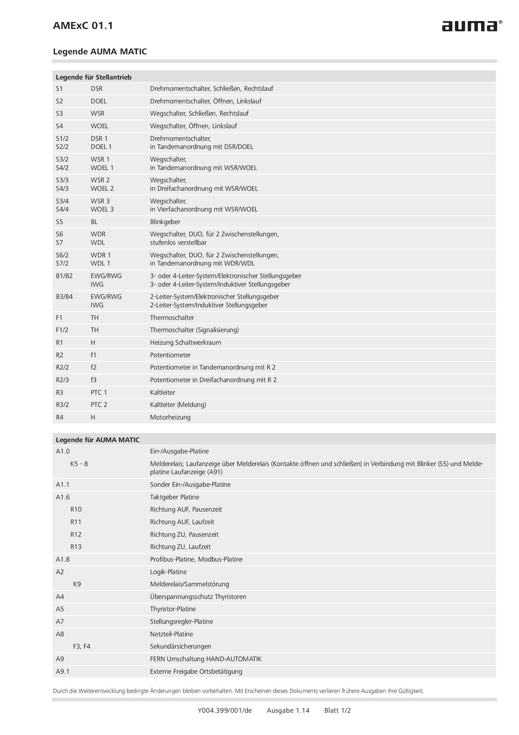
Legend AMExC 01.1
Wiring diagram

Legend SGC/SVC
Wiring diagram
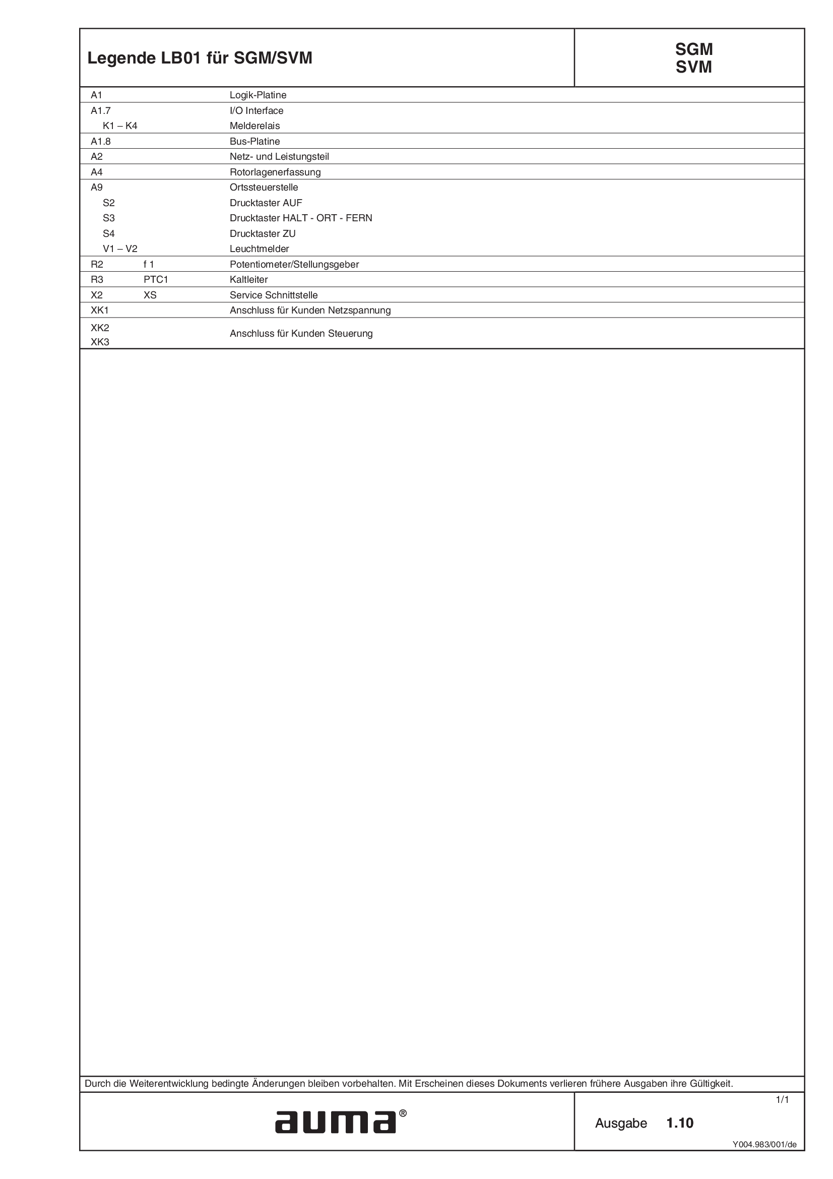
Legend SGM/SVM
Wiring diagram
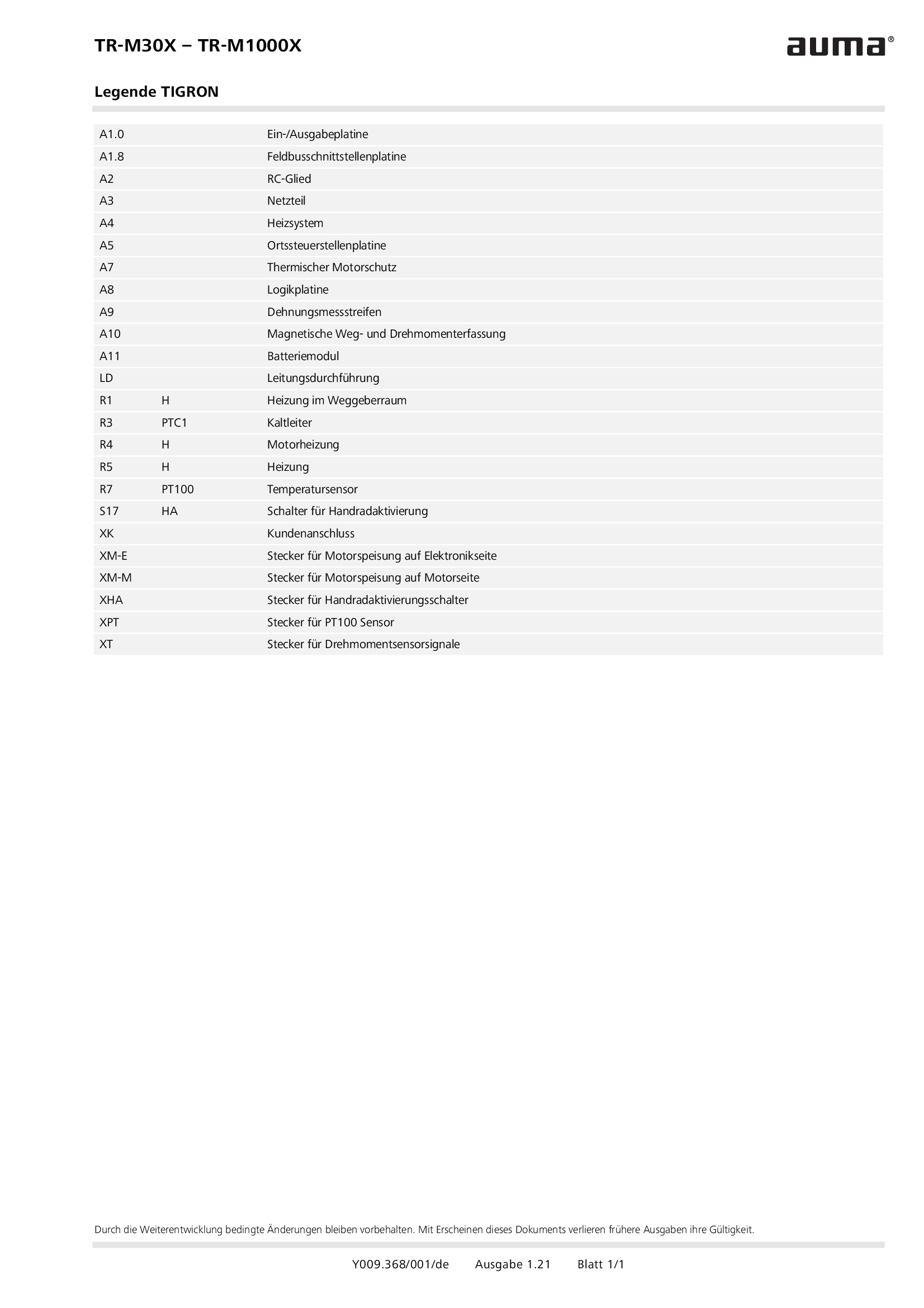
Legend TR-M30X – TR-M1000X
Wiring diagram
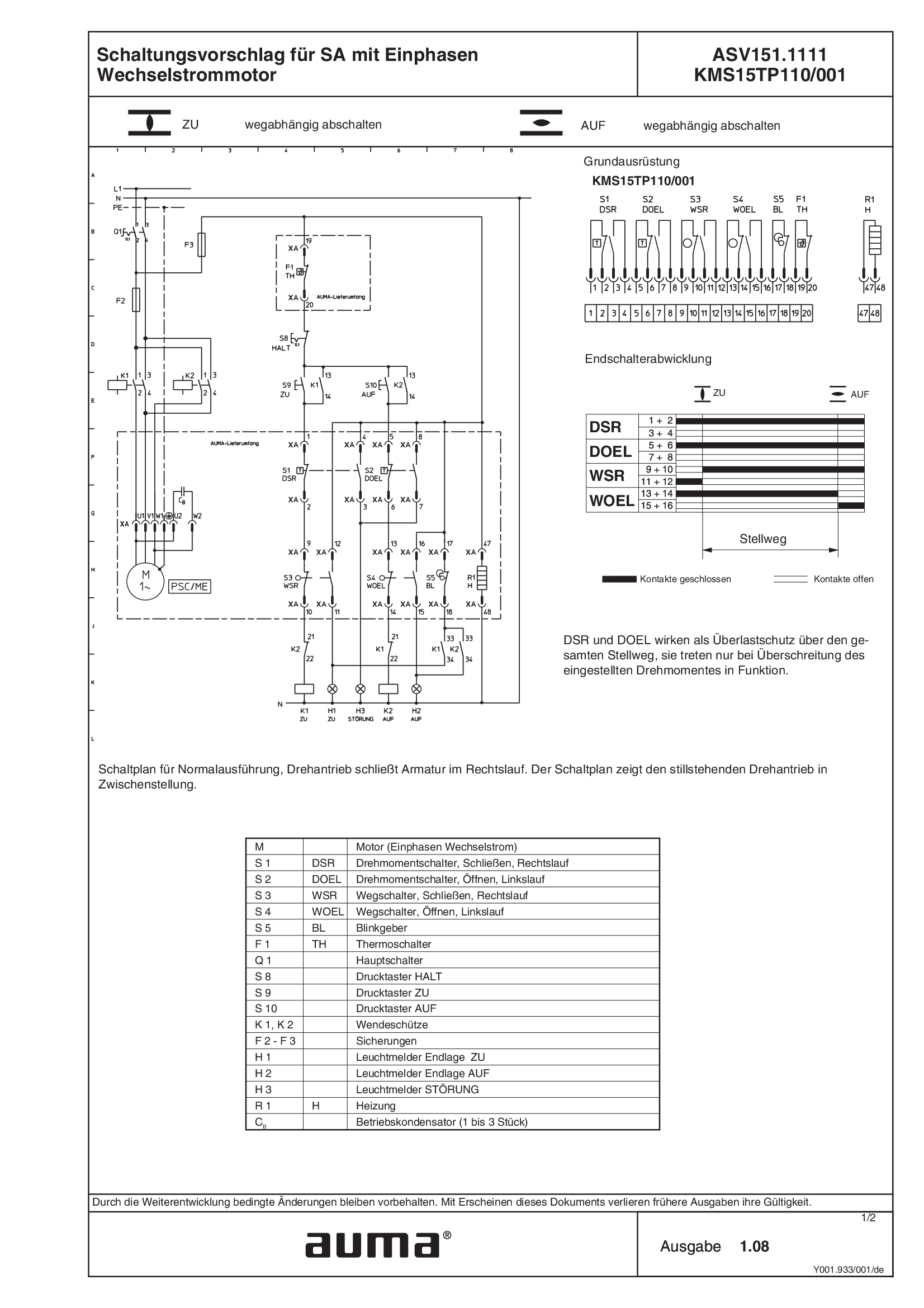
SA.1, 1-ph AC, ASV151.1111 /ASV151.1121 KMS15TP110/001
Wiring diagram
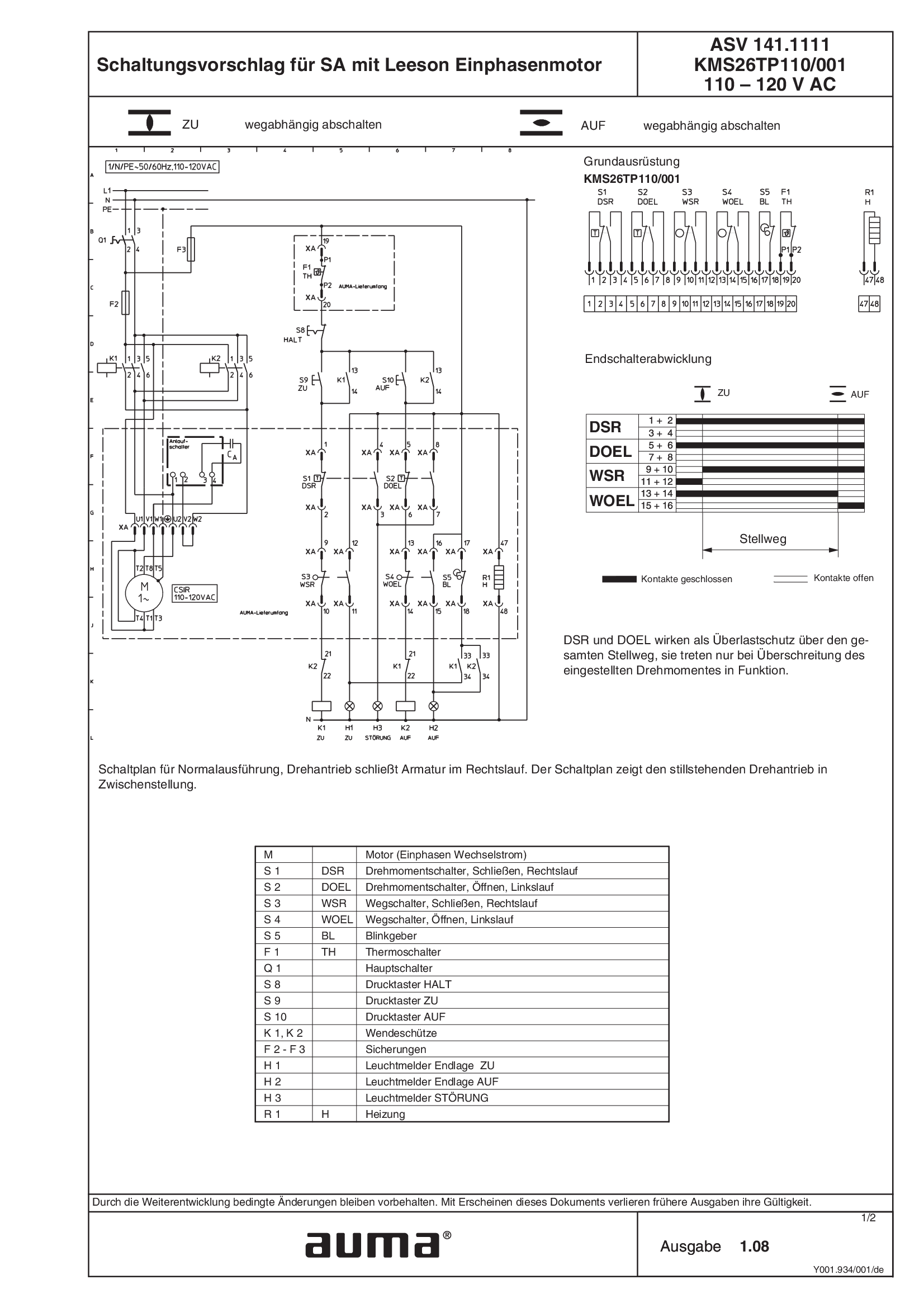
SA.1, 1-ph AC, Leeson motor ASV141.1111 /ASV141.1121 KMS26TP110/001 110 - 120 V AC
Wiring diagram
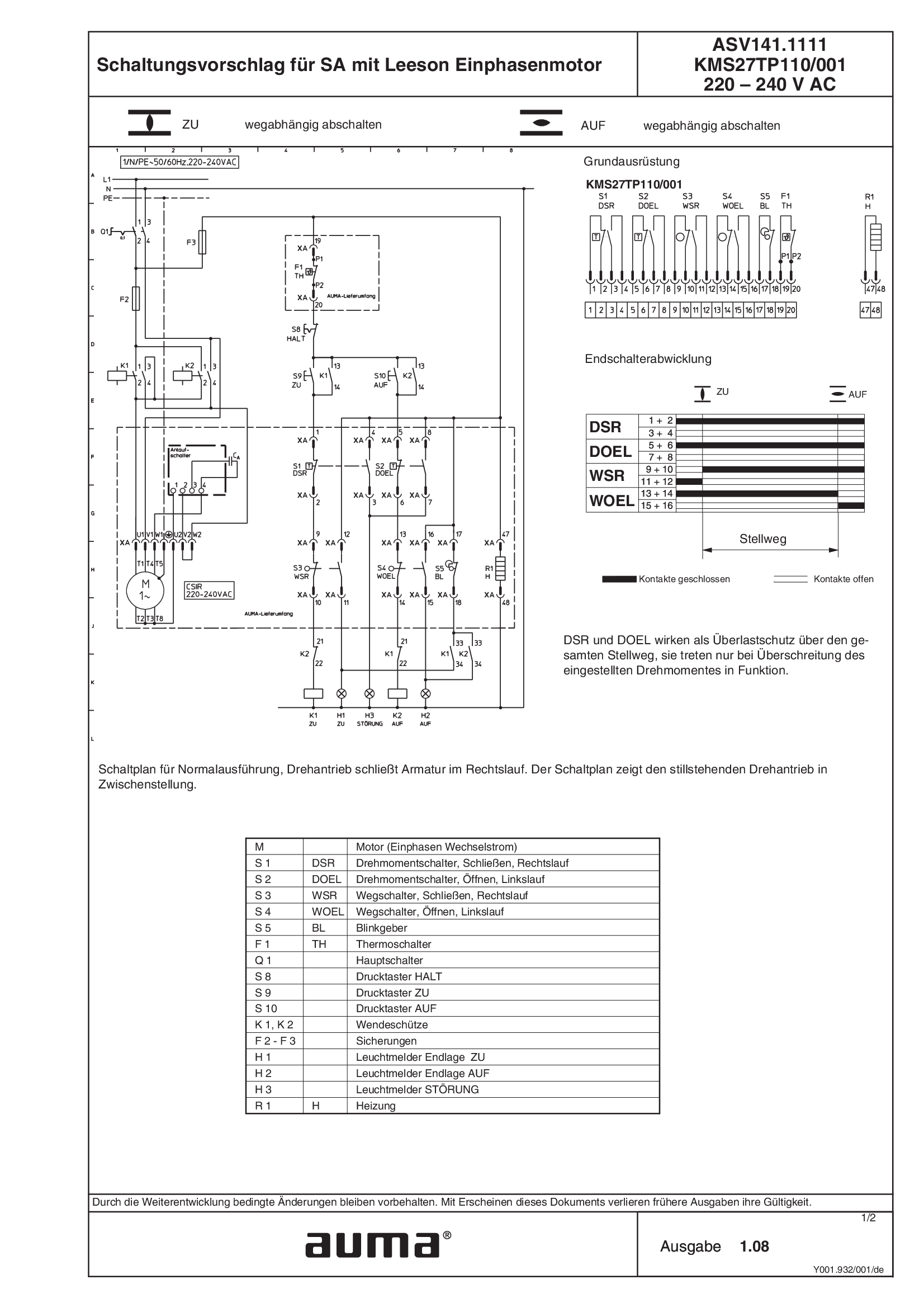
SA.1, 1-ph AC, Leeson motor ASV141.1111 /ASV141.1121 KMS27TP110/001 220 - 240 V AC
Wiring diagram
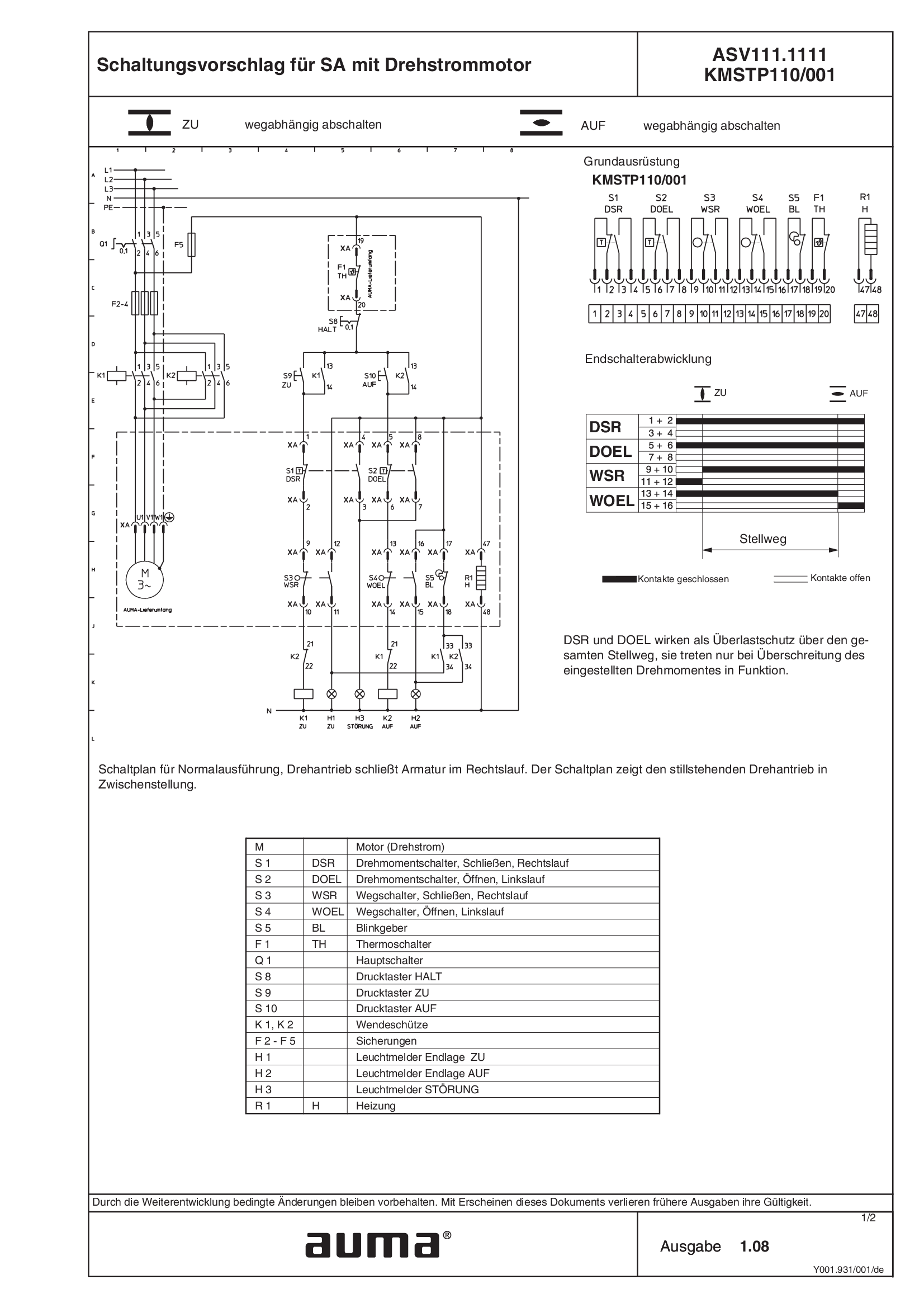
SA.1, 3-ph AC ASV111.1111 /ASV111.1121 KMSTP110/001
Wiring diagram
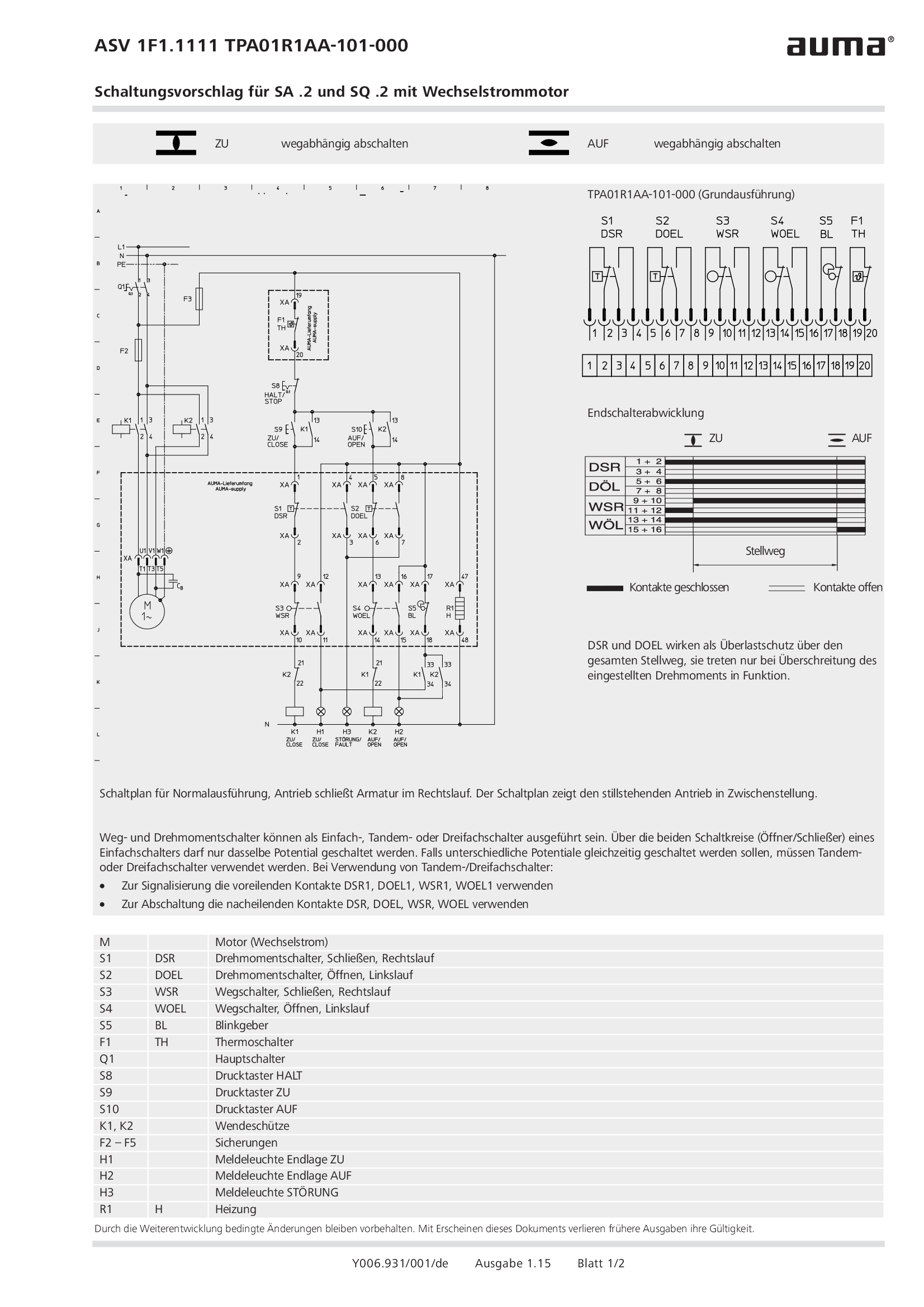
SA.2/SQ.2, 1-ph AC ASV1F1.1111 /ASV1F1.1121 TPA01R1AA-101-000
Wiring diagram
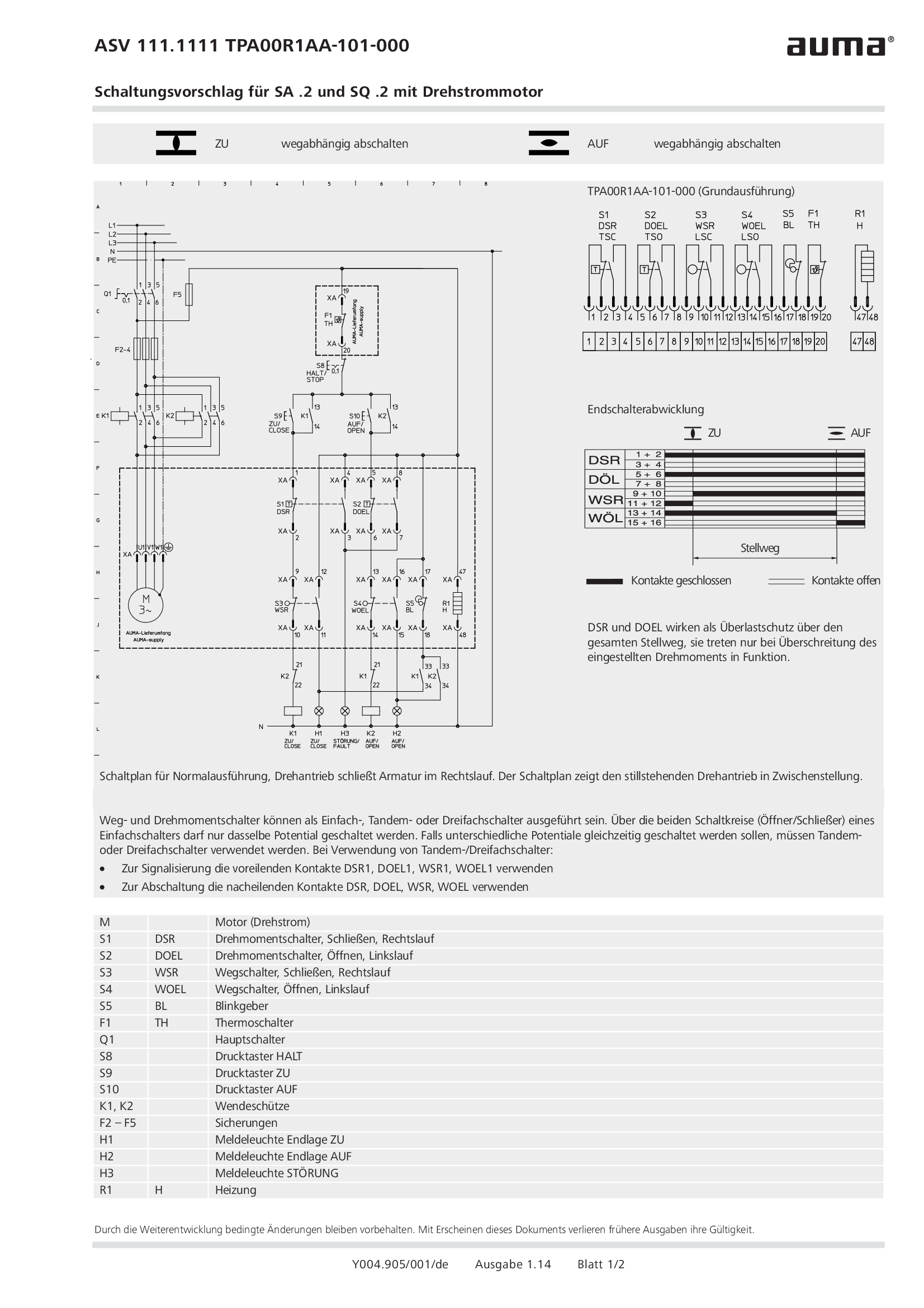
SA.2/SQ.2, 3-ph AC ASV111.1111 /ASV111.1121 TPA00R1AA-101-000
Wiring diagram
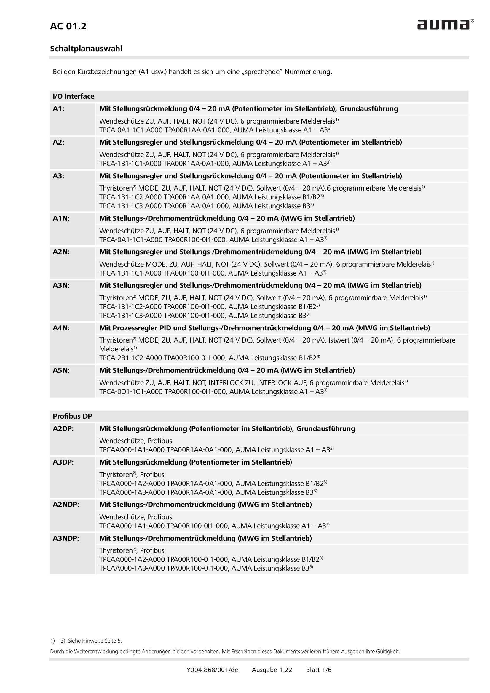
Selection for wiring diagram for AUMATIC AC 01.2
Wiring diagram
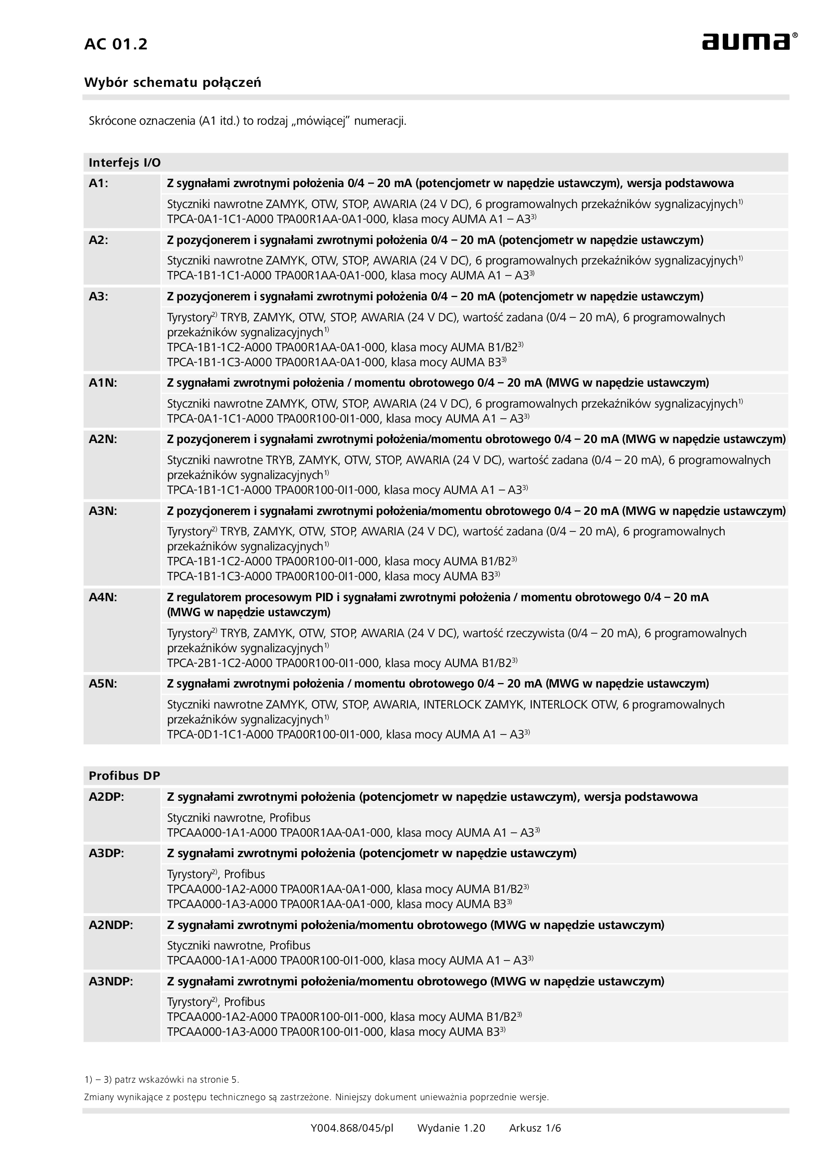
Selection for wiring diagram for AUMATIC AC 01.2/ACExC 01.2
Wiring diagram
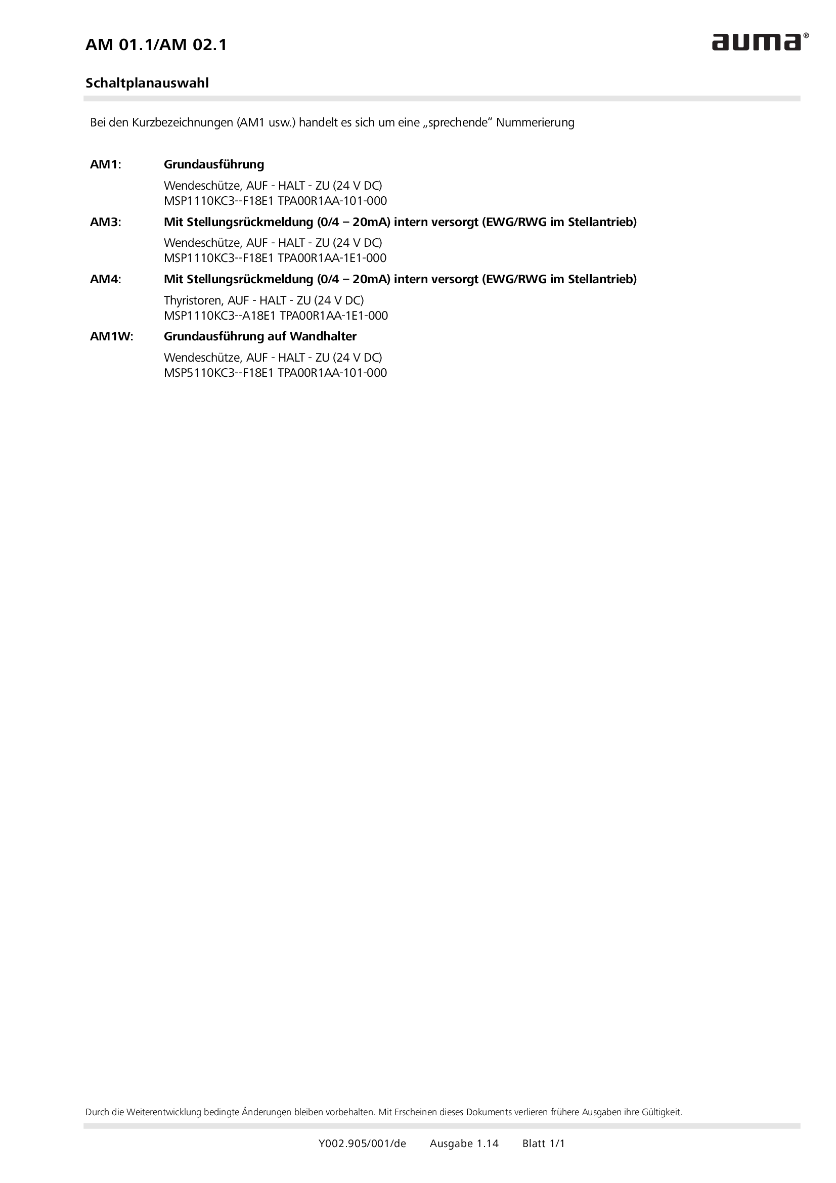
Selection of wiring diagrams for MATIC AM 01.1/AM 02. 1
Wiring diagram
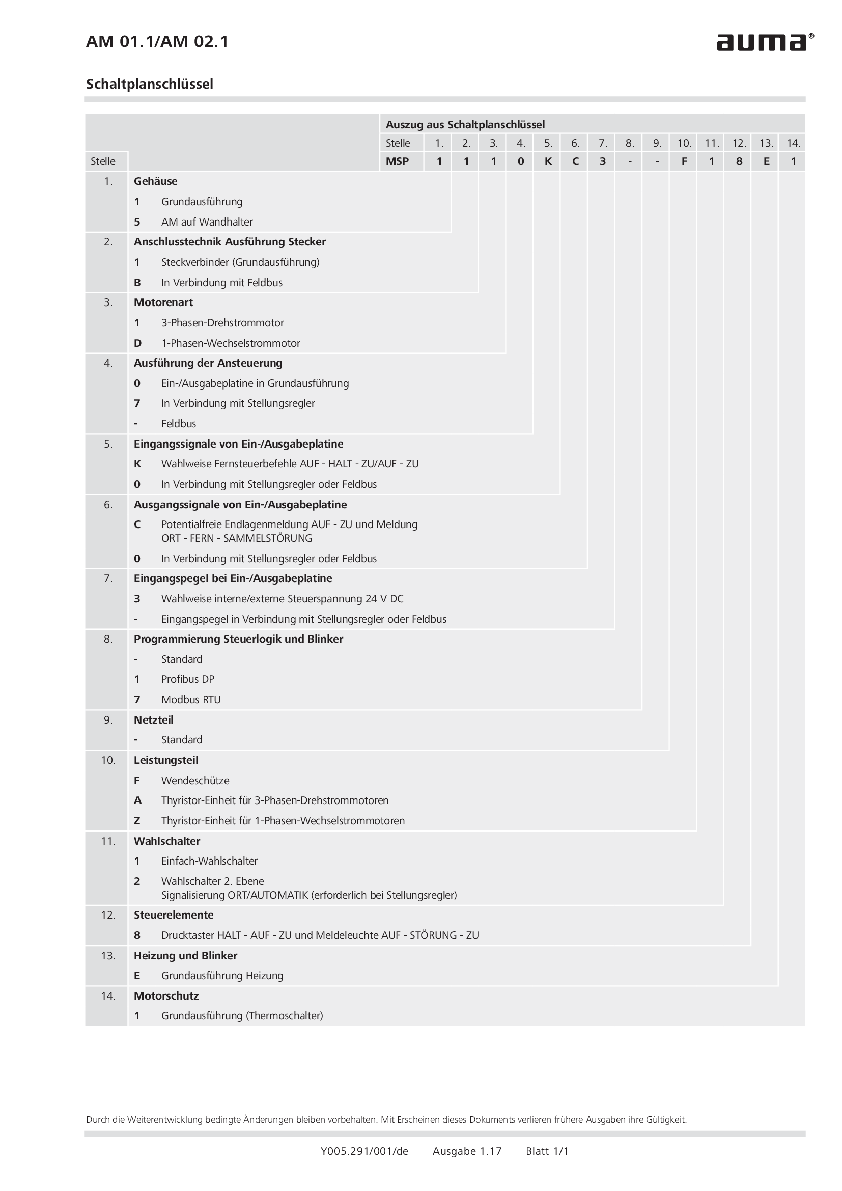
Wiring diagram code AM 01.1/AM 02.1
Wiring diagram
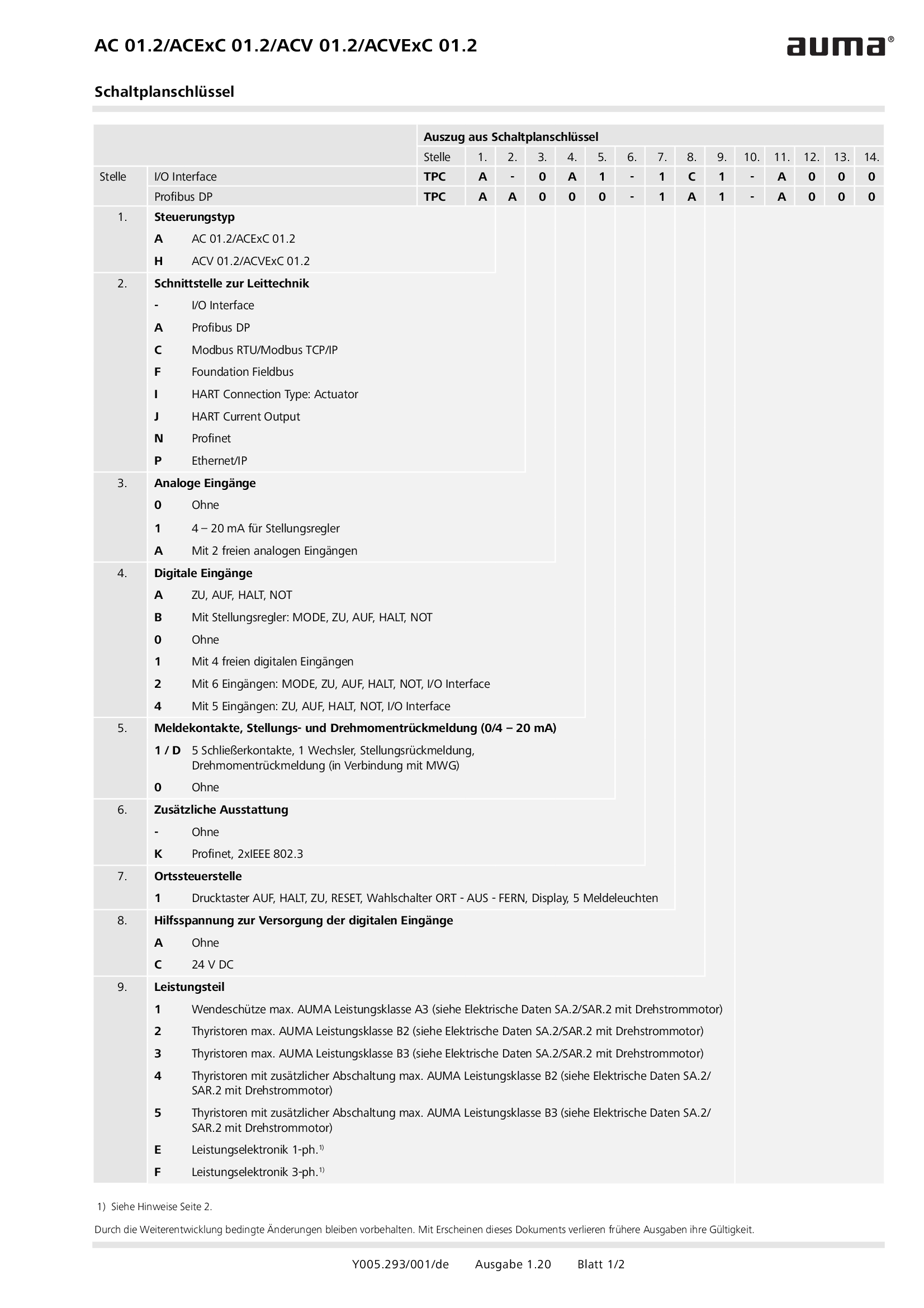
Wiring diagram code for AC 01.2/ACExC 01.2/ACV 01.2/ACVExC 01.2
Wiring diagram
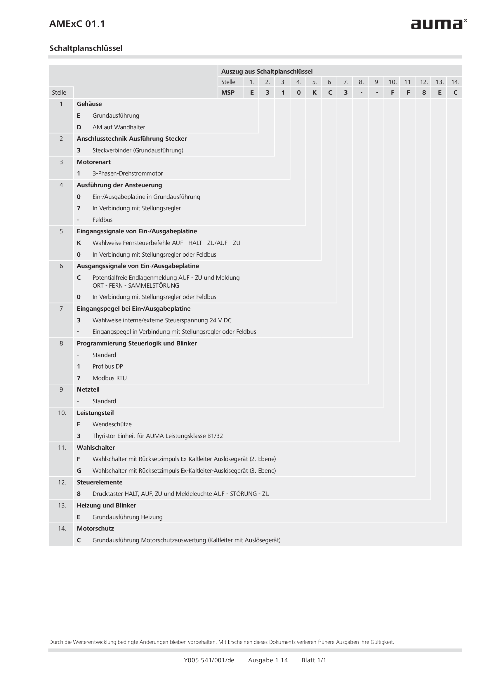
Wiring diagram code for AMExC 01.1
Wiring diagram


