Результаты поиска для
"Supplement Special version for counterclockwise closing"
Wiring diagram

AV2HRT: AUMATIC ACVExC 01.2 position feedback (potentiometer in actuator), basic version, HART, 1-ph; 220 V - 240 V
Wiring diagram

AV2HRT: AUMATIC ACVExC 01.2 position feedback (potentiometer in actuator), basic version, HART, 3-ph; 380 V - 480 V
Wiring diagram

AV2HRTCO: AUMATIC ACV 01.2 position feedback (potentiometer in actuator), basic version, HART Current Output, 1-ph; 220 V - 240 V
Wiring diagram

AV2HRTCO: AUMATIC ACV 01.2 position feedback (potentiometer in actuator), basic version, HART Current Output, 3-ph; 380 V- 480 V
Wiring diagram

AV2HRTCO: AUMATIC ACVExC 01.2 position feedback (potentiometer in actuator), basic version, HART Current Output, 1-ph; 220 V - 240 V
Wiring diagram

AV2HRTCO: AUMATIC ACVExC 01.2 position feedback (potentiometer in actuator), basic version, HART Current Output, 3-ph; 38 V - 480 V
Wiring diagram

AV2HRTCO: AUMATIC ACVExC 01.2 position feedback (potentiometer in actuator), basic version, HART Current Output, 3-ph; 380 V - 480 V
Wiring diagram

AV2MB: AUMATIC ACV 01.2 position feedback signal (potentiometer in actuator), basic version, Modbus, 1-ph; 220 V- 240 V
Wiring diagram

AV2MB: AUMATIC ACV 01.2 position feedback signal (potentiometer in actuator), basic version, Modbus, 3-ph; 380 V - 480 V
Wiring diagram

AV2MB: AUMATIC ACVExC 01.2 position feedback (potentiometer in actuator), basic version, Modbus RTU, 1-ph; 220 V - 240 V
Wiring diagram

AV2MB: AUMATIC ACVExC 01.2 position feedback (potentiometer in actuator), basic version, Modbus RTU, 3ph; 220 V - 240 V
Wiring diagram

AV2MB: AUMATIC ACVExC 01.2 position feedback (potentiometer in actuator), basic version, Modbus RTU, 3ph; 380 V - 480 V
Wiring diagram

AV2MBTCP: AUMATIC ACV 01.2 position feedback (potentiometer in actuator), basic version, Modbus TCP/IP, 1-ph; 220 V - 240 V
Wiring diagram

AV2MBTCP: AUMATIC ACV 01.2 position feedback (potentiometer in actuator), basic version, Modbus TCP/IP, 3-ph; 380 V - 480 V
Wiring diagram

AV2MBTCP: AUMATIC ACVExC 01.2 position feedback (ptentiometer in actuator), basic version Modbus TCP/IP, 1-ph; 220 V - 240 V
Wiring diagram

AV2MBTCP: AUMATIC ACVExC 01.2 position feedback (ptentiometer in actuator), basic version Modbus TCP/IP, 3-ph; 380 V - 480 V
Wiring diagram

AV4DP: AUMATIC ACV 01.2 positioner and position feedback signal 0/4 – 20 mA (potentiometer in actuator), basic version, MODE, CLOSE, OPEN, STOP, EMERGENCY, I/O (24 V DC), 6 programmable output contacts, Profibus, 1-ph; 220 V - 240 V
Wiring diagram

AV4DP: AUMATIC ACV 01.2 positioner and position feedback signal 0/4 – 20 mA (potentiometer in actuator), basic version, MODE, CLOSE, OPEN, STOP, EMERGENCY, I/O (24 V DC), 6 programmable output contacts, Profibus, 3-ph; 380 V - 480 V
Wiring diagram

AV4DP: AUMATIC ACVExC 01.2 positioner und position feedback signal 0/4 - 20 mA (potentiometer in actuator), basic version, MODE, CLOSE, OPEN, STOP, EMERGENCY, I/O ( 24 V DC), 6 programmable output contacts, Profibus DP, 1-ph; 220 V - 240 V
Wiring diagram

AV4DP: AUMATIC ACVExC 01.2 positioner und position feedback signal 0/4 - 20 mA (potentiometer in actuator), basic version, MODE, CLOSE, OPEN, STOP, EMERGENCY, I/O ( 24 V DC), 6 programmable output contacts, Profibus DP, 3-ph; 380 V - 480 V
Wiring diagram

AV4FF: AUMATIC ACExC 01.2 positioner and position feedback signal 0/4 - 20 mA (potentiometer in actuator), basic version, MODE, CLOSE, OPEN, STOP, EMERGENCY, I/O ( 24 V DC), 6 programmable output contacts, Foundation Fieldbus FF, 1-ph; 220 V - 240 V
Wiring diagram

AV4FF: AUMATIC ACExC 01.2 positioner and position feedback signal 0/4 - 20 mA (potentiometer in actuator), basic version, MODE, CLOSE, OPEN, STOP, EMERGENCY, I/O ( 24 V DC), 6 programmable output contacts, Foundation Fieldbus FF, 3-ph; 380 V - 480 V
Wiring diagram

AV4FF: AUMATIC ACV 01.2 positioner and position feedback signal 0/4 – 20 mA (potentiometer in actuator), basic version, MODE, CLOSE, OPEN, STOP, EMERGENCY, I/O (24 V DC), 6 programmable output contacts, Foundation Fieldbus, 1-ph; 220 V - 240 V
Wiring diagram

AV4FF: AUMATIC ACV 01.2 positioner and position feedback signal 0/4 – 20 mA (potentiometer in actuator), basic version, MODE, CLOSE, OPEN, STOP, EMERGENCY, I/O (24 V DC), 6 programmable output contacts, Foundation Fieldbus, 3-ph; 380 V - 480 V
Wiring diagram

AV4HRT: AUMATIC ACV 01.2 positioner and position feedback signal 0/4 – 20 mA (potentiometer in actuator), basic version, MODE, CLOSE, OPEN, STOP, EMERGENCY, I/O (24 V DC), 6 programmable output contacts, HART, 1-ph; 220 V - 240 V
Wiring diagram

AV4HRT: AUMATIC ACV 01.2 positioner and position feedback signal 0/4 – 20 mA (potentiometer in actuator), basic version, MODE, CLOSE, OPEN, STOP, EMERGENCY, I/O (24 V DC), 6 programmable output contacts, HART, 3-ph; 380 V - 480 V
Wiring diagram

AV4HRT: AUMATIC ACVExC 01.2 positioner and position feedback signal 0/4 - 20 mA (potentiometer in actuator), basic version, MODE, CLOSE, OPEN, STOP, EMERGENCY; I/O (24 V DC), 6 programmable output contacts, HART, 1-ph; 220 V - 240 V
Wiring diagram

AV4HRT: AUMATIC ACVExC 01.2 positioner and position feedback signal 0/4 - 20 mA (potentiometer in actuator), basic version, MODE, CLOSE, OPEN, STOP, EMERGENCY; I/O (24 V DC), 6 programmable output contacts, HART, 3-ph; 380 V - 480 V
Wiring diagram

AV4HRTCO: AUMATIC ACV 01.2 positioner and position feedback signal 0/4 – 20 mA (potentiometer in actuator), basic version, MODE, CLOSE, OPEN, STOP, EMERGENCY, I/O (24 V DC), 6 programmable output contacts, HART, 1-ph; 220 V - 240 V
Wiring diagram

AV4HRTCO: AUMATIC ACV 01.2 positioner and position feedback signal 0/4 – 20 mA (potentiometer in actuator), basic version, MODE, CLOSE, OPEN, STOP, EMERGENCY, I/O (24 V DC), 6 programmable output contacts, HART, 3-ph; 380 V - 480 V
Wiring diagram

AV4HRTCO: AUMATIC ACVExC 01.2 positioner and position feedback signal 0/4 - 20 mA (potentiometer in actuator), basic version, MODE, CLOSE, OPEN, STOP, EMERGENCY, I/O (24 V DC), 6 programmable output contacts, HART Current output, 1-ph; 220 V - 240 V
Wiring diagram

AV4HRTCO: AUMATIC ACVExC 01.2 positioner and position feedback signal 0/4 - 20 mA (potentiometer in actuator), basic version, MODE, CLOSE, OPEN, STOP, EMERGENCY, I/O (24 V DC), 6 programmable output contacts, HART Current output, 3-ph; 380 V - 480 V
Wiring diagram

AV4MB: AUMATIC ACV 01.2 positioner and position feedback signal 0/4 – 20 mA (potentiometer in actuator), basic version, MODE, CLOSE, OPEN, STOP, EMERGENCY, I/O (24 V DC), 6 programmable output contacts, Modbus, 1-ph; 220 V - 240 V
Wiring diagram

AV4MB: AUMATIC ACV 01.2 positioner and position feedback signal 0/4 – 20 mA (potentiometer in actuator), basic version, MODE, CLOSE, OPEN, STOP, EMERGENCY, I/O (24 V DC), 6 programmable output contacts, Modbus, 3-ph; 380 V - 480 V
Wiring diagram

AV4MB: AUMATIC ACVExC 01.2 positionier and position feedback signal 0/4 - 20 mA (potentiometer in actuator), basic version, MODE, CLOSE, OPEN, STOP, EMERGENCY, I/O (24 V DC), 6 programmable output contacts, Modbus RTU, 1-ph; 220 V - 240 V
Wiring diagram

AV4MB: AUMATIC ACVExC 01.2 positionier and position feedback signal 0/4 - 20 mA (potentiometer in actuator), basic version, MODE, CLOSE, OPEN, STOP, EMERGENCY, I/O (24 V DC), 6 programmable output contacts, Modbus RTU, 3-ph; 380 V - 480 V
Wiring diagram

AV4MBTCP: AUMATIC ACV 01.2 positioner and position feedback signal 0/4 – 20 mA (potentiometer in actuator), basic version, MODE, CLOSE, OPEN, STOP, EMERGENCY, I/O (24 V DC), 6 programmable output contacts, Modbus TCP/IP, 1-ph; 220 V - 240 V
Wiring diagram

AV4MBTCP: AUMATIC ACV 01.2 positioner and position feedback signal 0/4 – 20 mA (potentiometer in actuator), basic version, MODE, CLOSE, OPEN, STOP, EMERGENCY, I/O (24 V DC), 6 programmable output contacts, Modbus TCP/IP, 3-ph; 380 V - 480 V
Wiring diagram

AV4MBTCP: AUMATIC ACVExC 01.2 positioner and position feedbak signal 0/4 - 20 mA (potentiometer in actuator), basic version, MODE, CLOSE, OPEN, STOP, EMERGENCY, I/O (24 V DC), 6 programmable output contacts, Modbus TCP/IP 1-ph; 220 V - 240 V
Wiring diagram

AV4MBTCP: AUMATIC ACVExC 01.2 positioner and position feedbak signal 0/4 - 20 mA (potentiometer in actuator), basic version, MODE, CLOSE, OPEN, STOP, EMERGENCY, I/O (24 V DC), 6 programmable output contacts, Modbus TCP/IP 3-ph; 380 V - 480 V
Wiring diagram
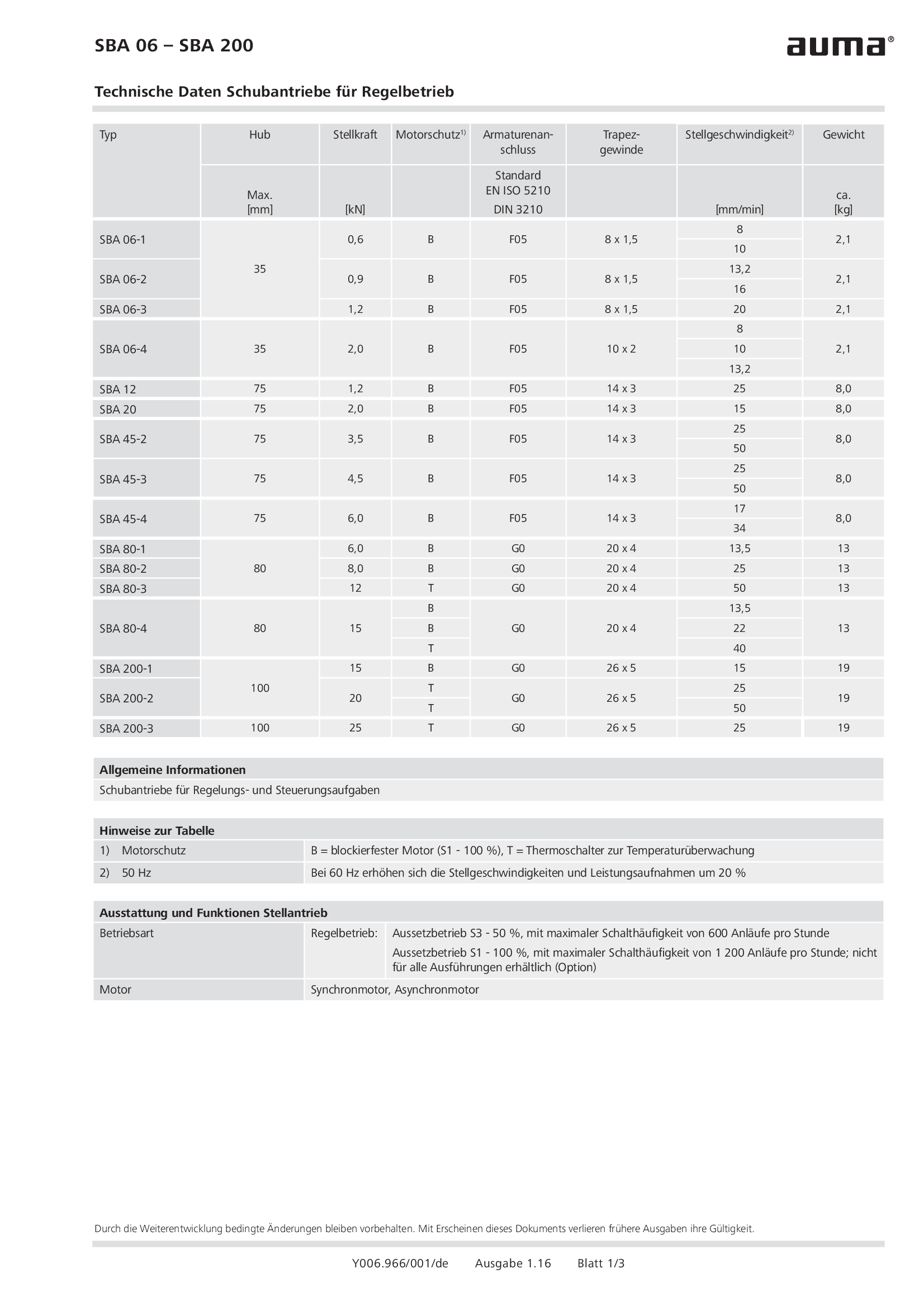
Linear actuators SBA 06 - 200 for modulating duty
Wiring diagram
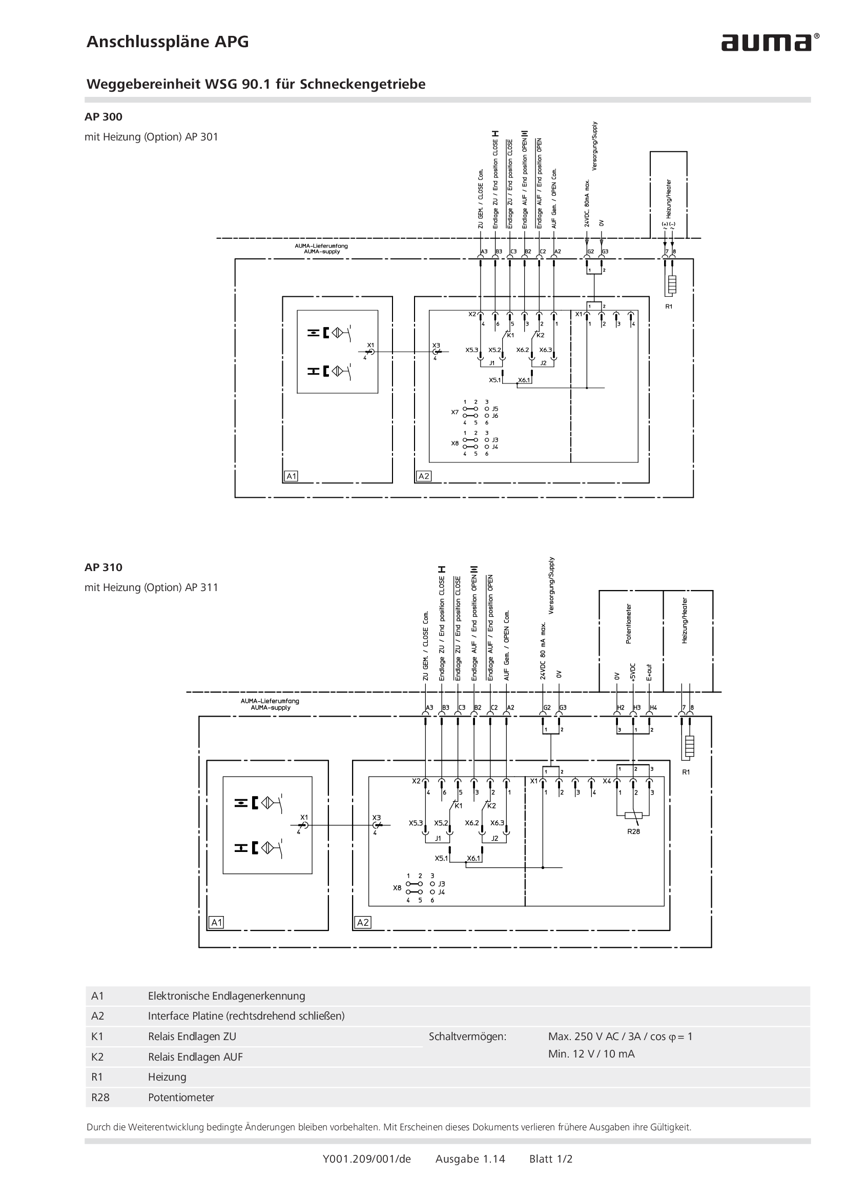
Overview terminal plans APG Valve position indicator WSG 90.1 for worm gearboxes
Wiring diagram

Part-turn actuators SGC/SGCR, Valve actuators SVC/SVCR (basic version)
Wiring diagram

Part-turn actuators SGM/SGMR, Valve actuators SVM/SVMR (basic version)
Wiring diagram

Selection for wiring diagram for ACV 01.2
Wiring diagram
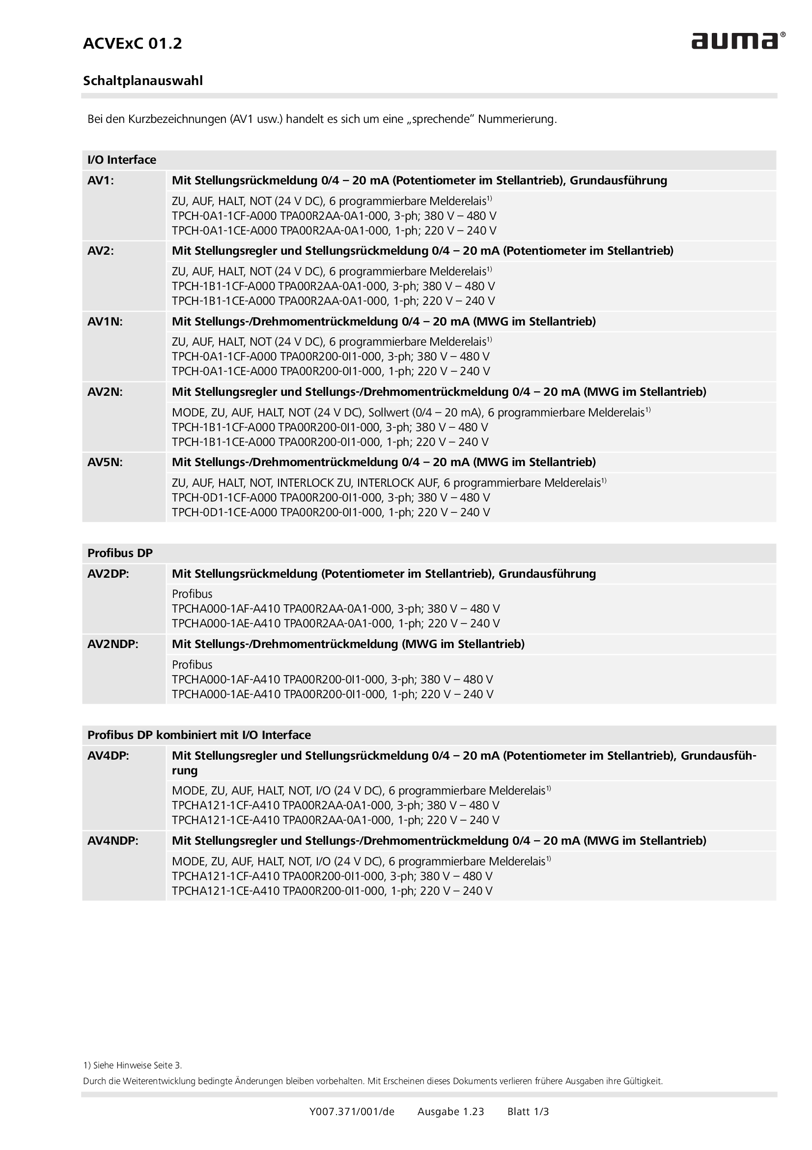
Selection for wiring diagram for ACVExC 01.2
Wiring diagram
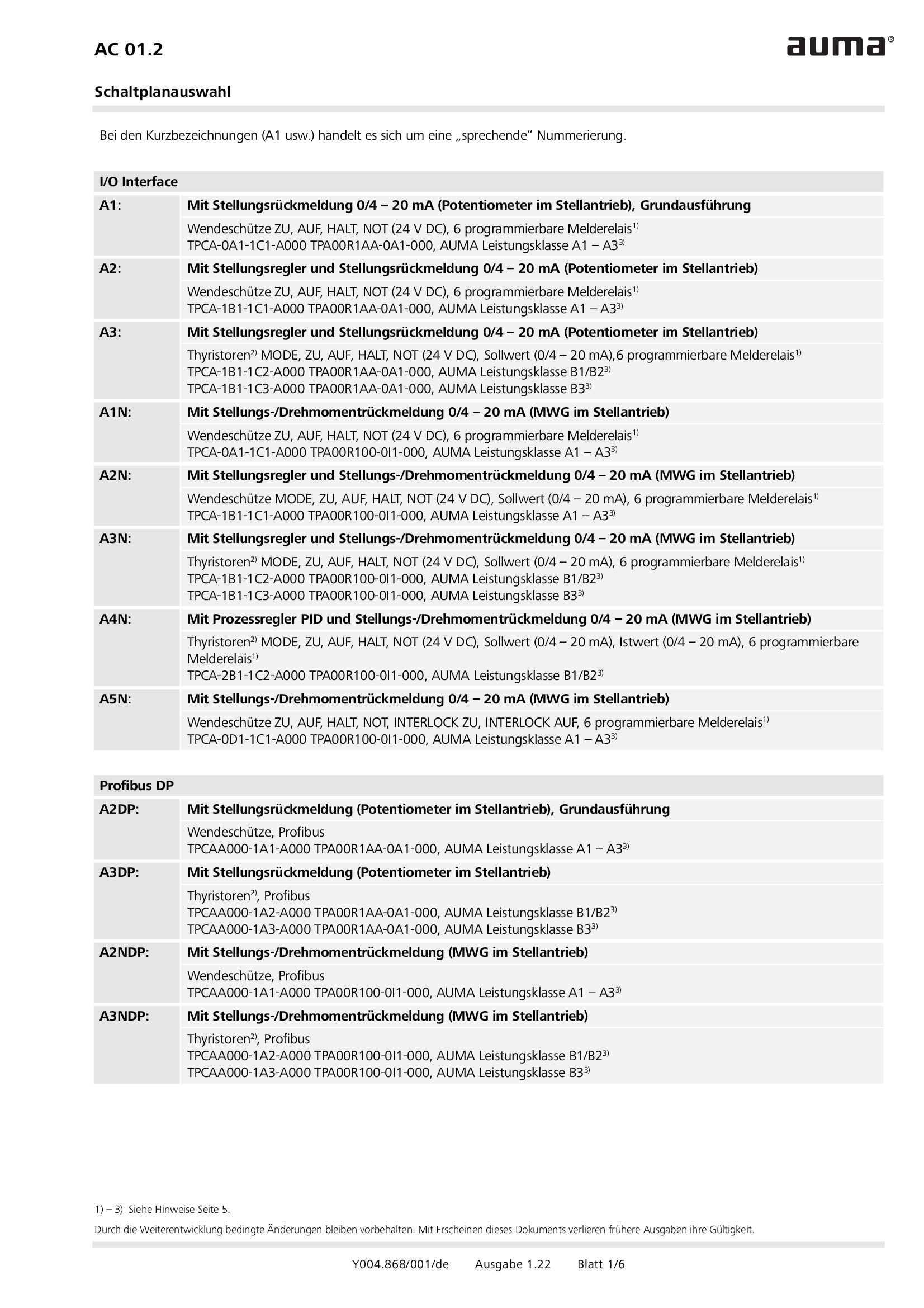
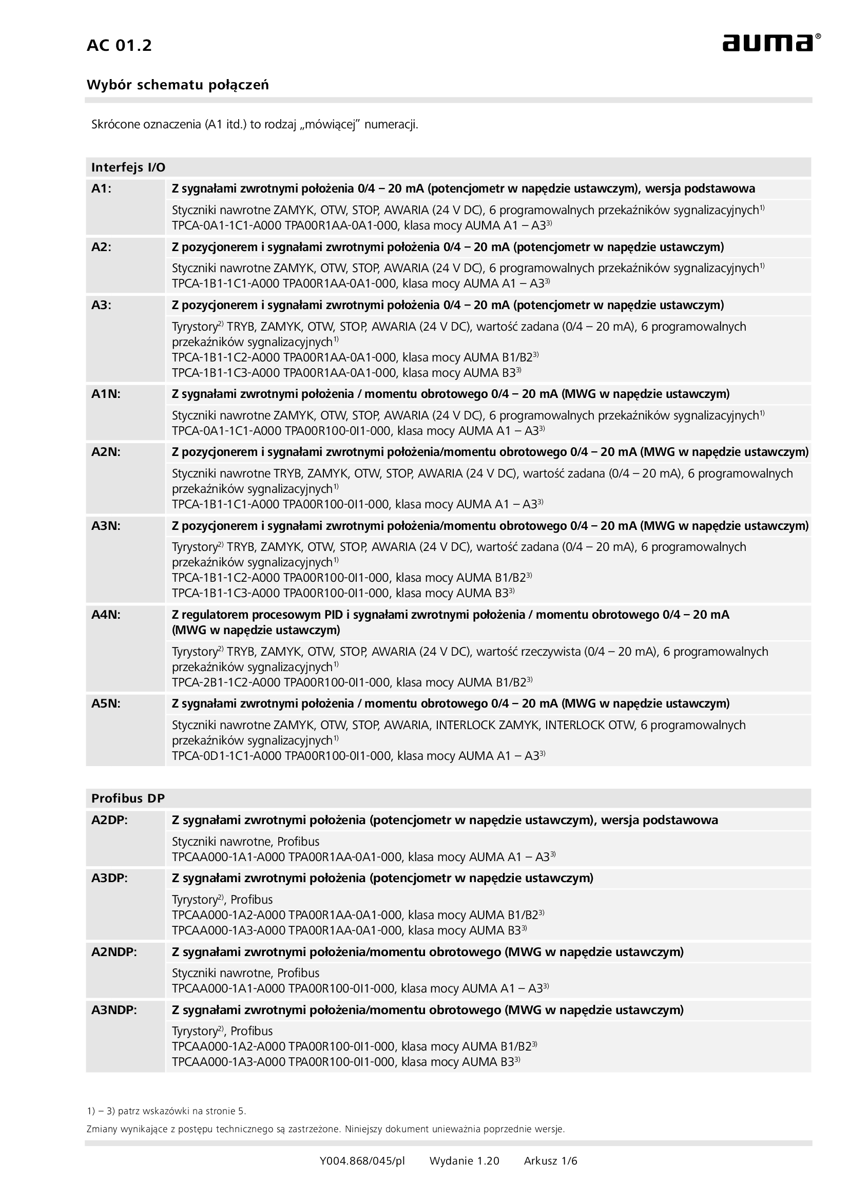
Selection for wiring diagram for AUMATIC AC 01.2
Wiring diagram
Selection for wiring diagram for AUMATIC AC 01.2/ACExC 01.2
Wiring diagram
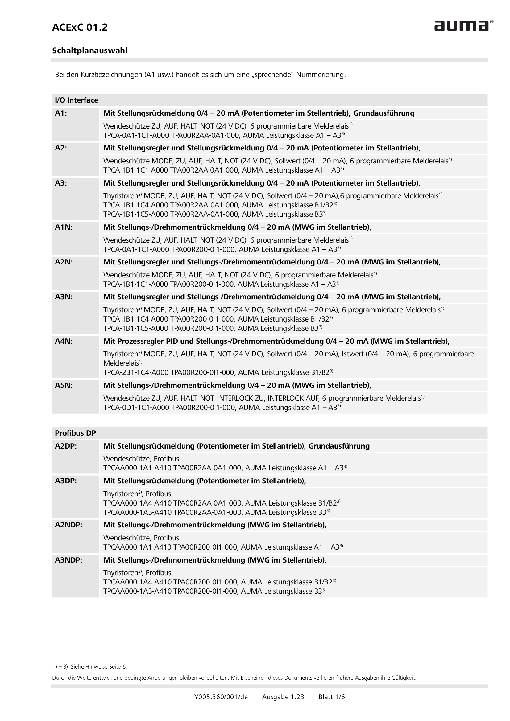
Selection for wiring diagram for AUMATIC ACExC 01.2
Wiring diagram
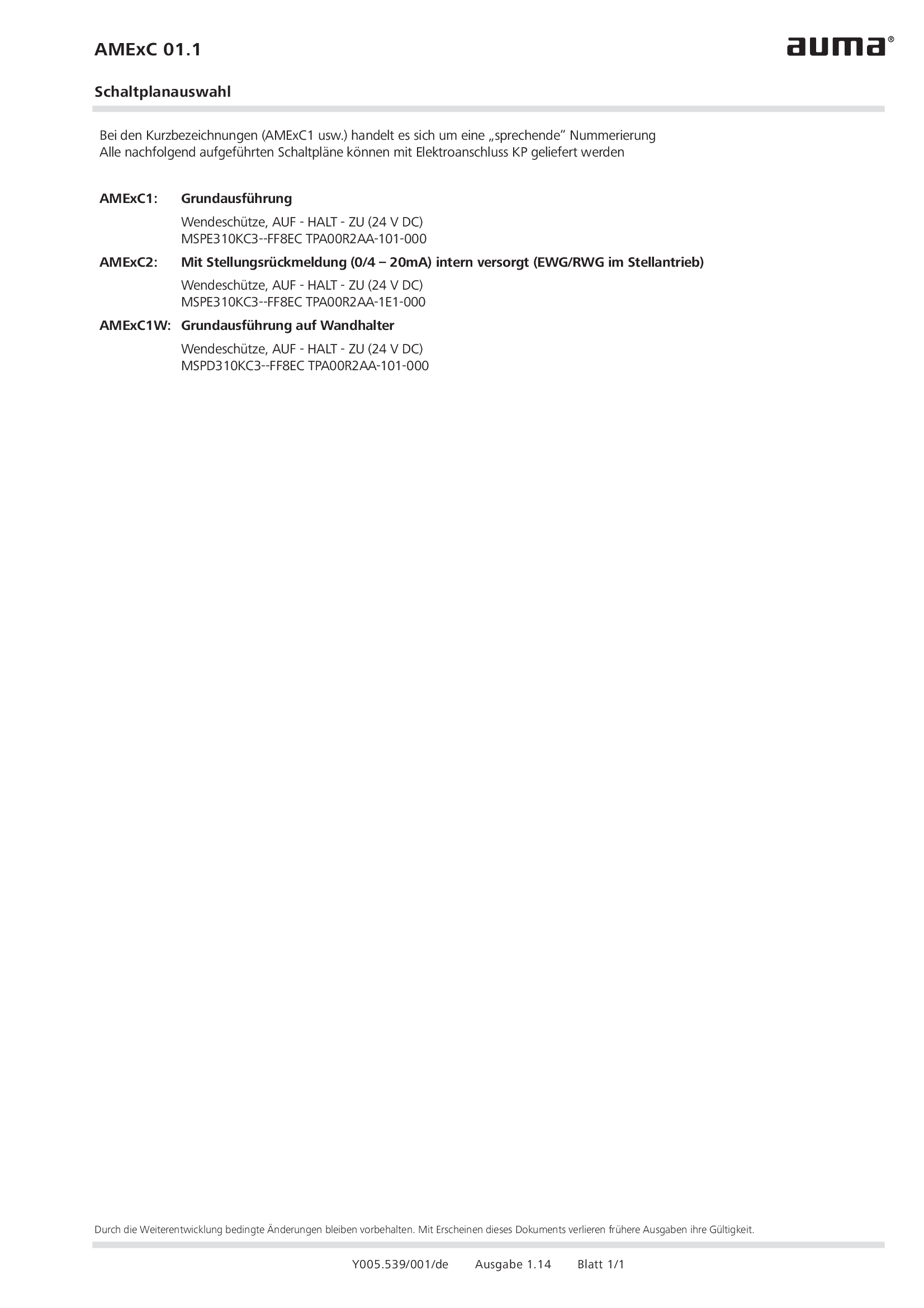
Selection of wiring diagrams for AUMA MATIC AMExC
Wiring diagram
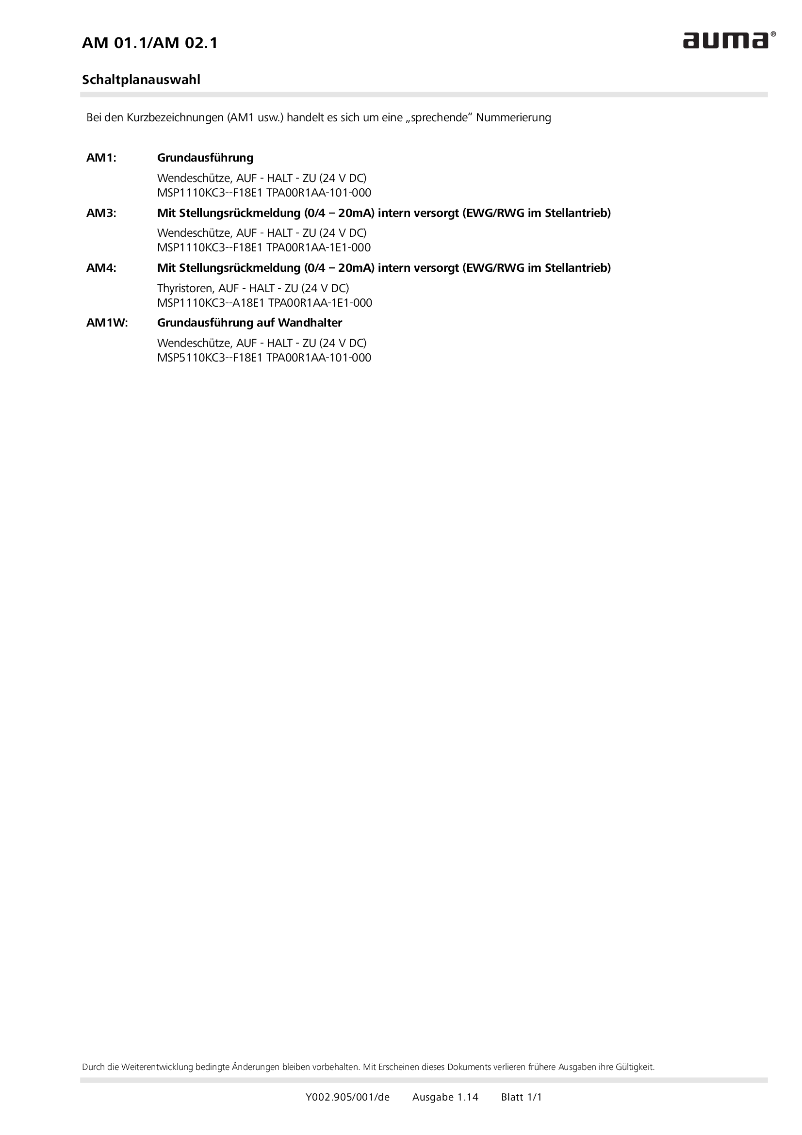
Selection of wiring diagrams for MATIC AM 01.1/AM 02. 1
Wiring diagram
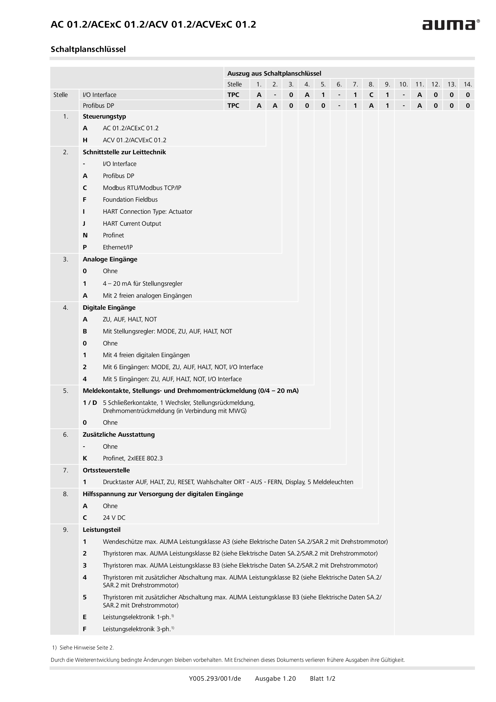
Wiring diagram code for AC 01.2/ACExC 01.2/ACV 01.2/ACVExC 01.2
Wiring diagram
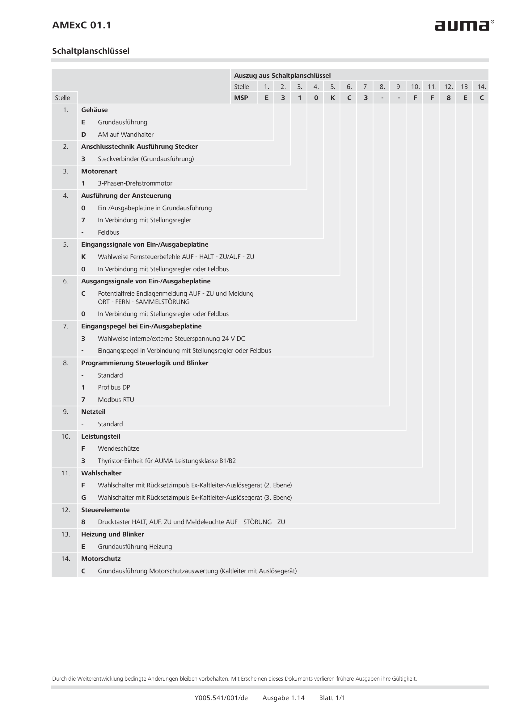
Wiring diagram code for AMExC 01.1
Wiring diagram