Результаты поиска для
"Declaration of Incorporation and Conformity for FQMEx 05.1, FQMEx 07.1, FQMEx 10.1, FQMEx 12.1"
Technical data
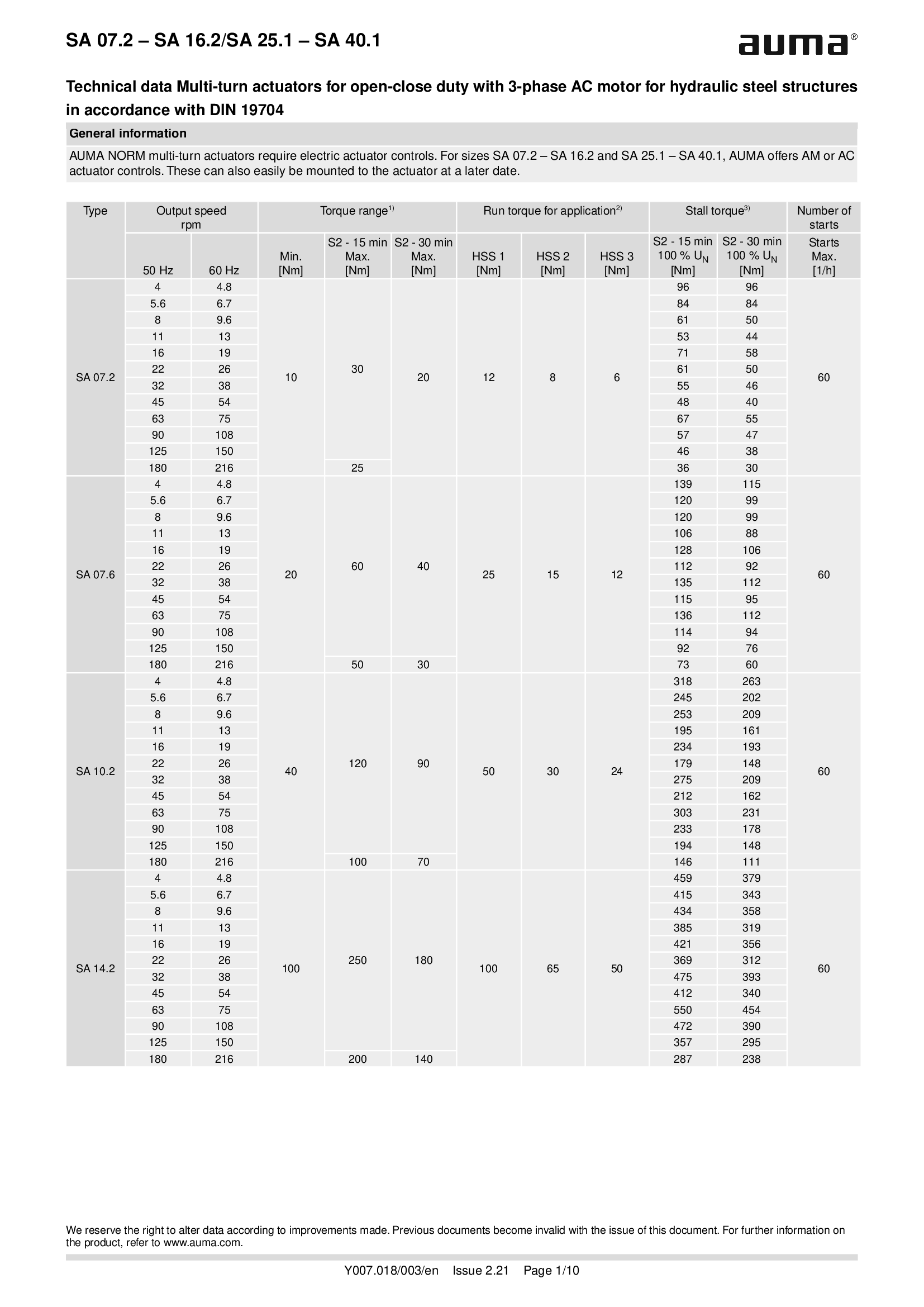
Multi-turn actuators SA 07.2 - 16.2/SA 25.1 - SA 40.1, open-close duty, 3-phase AC, for hydraulic steel structures
Technical data

Multi-turn actuators SA 07.2-UW - SA 16.2-UW, open-close duty, 3-phase AC, for continuous underwater use
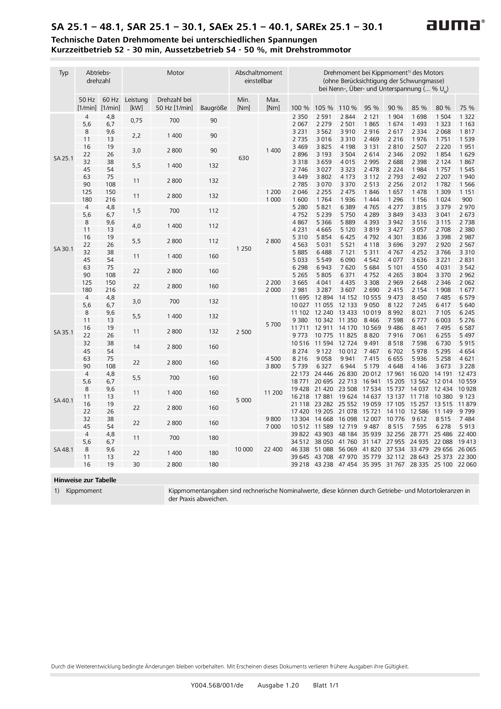
Technical data

Multi-turn actuators SA 25.1 - 48.1/SAEx 25.1 - 40.1, Torques for differential voltages, Short-time duty S2 - 15 min
Technical data
Multi-turn actuators SA 25.1 - 48.1/SAEx 25.1 - 40.1, Torques for differential voltages, Short-time duty S2 - 30 min
Technical data
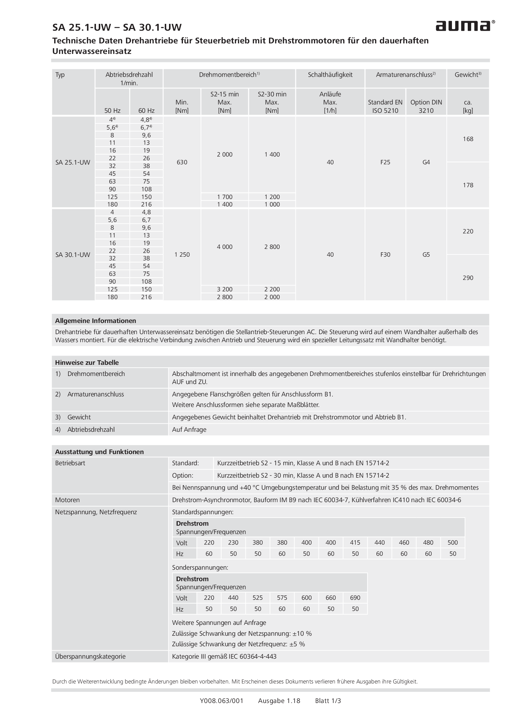
Multi-turn actuators SA 25.1-UW - SA 30.1-UW, open-close duty, 3-phase AC, for continuous underwater use
Technical data
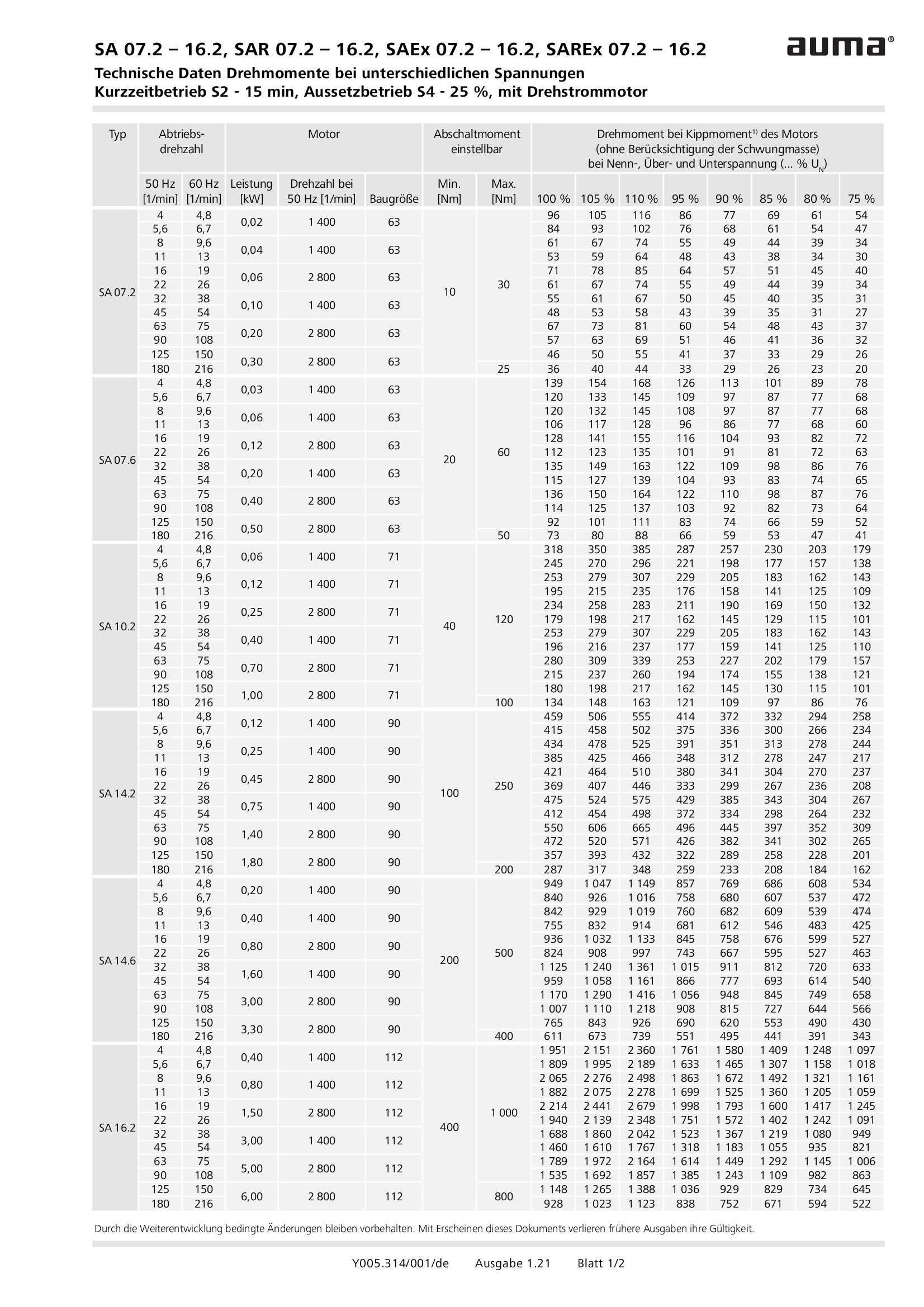
Multi-turn actuators SA/SAR 07.2 - 16.2 / SAEx/SAREx 07.2 - 16.2, Torques for differential voltages, Short-time duty S2 - 15 min, Intermittent duty S4 - 25 %
Technical data
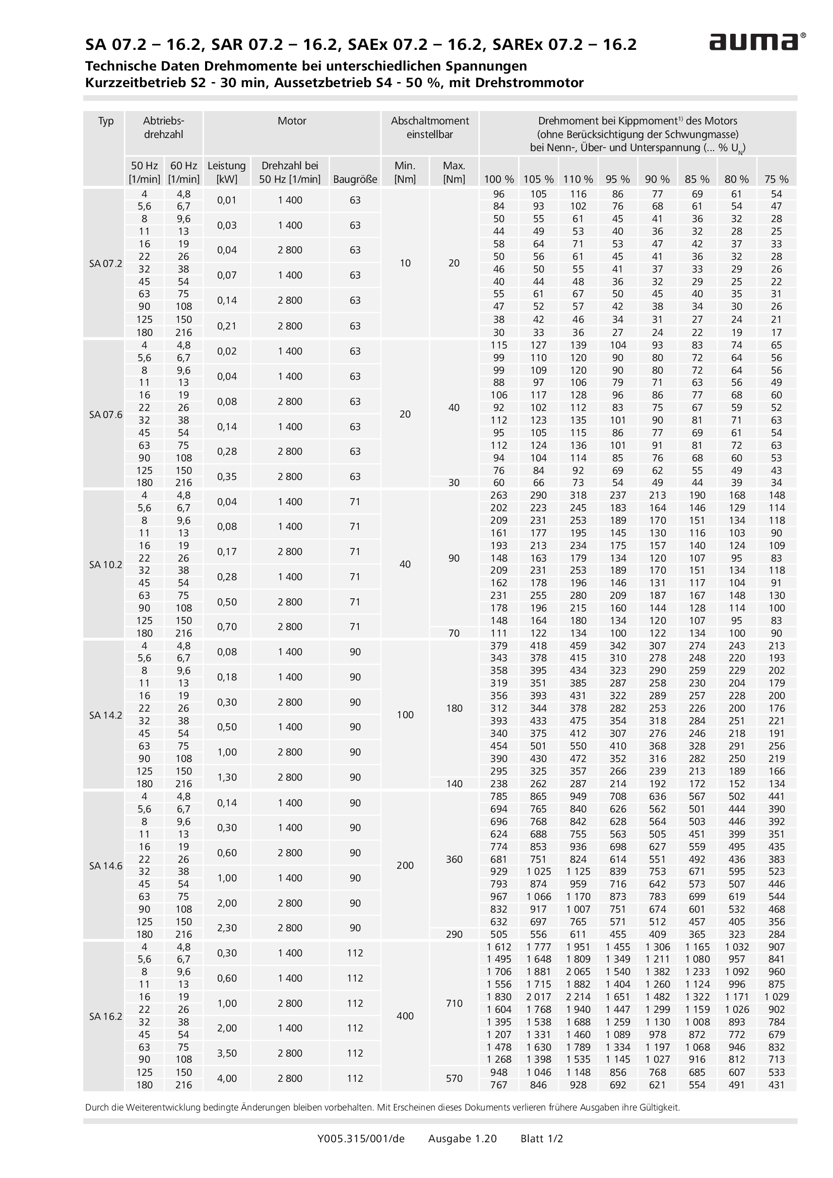
Multi-turn actuators SA/SAR 07.2 - 16.2 / SAEx/SAREx 07.2 - 16.2, Torques for differential voltages, Short-time duty S2 - 30 min, Intermittent duty S4 -50 %
Technical data

Multi-turn actuators SAEx 07.2 - 07.6, open-close duty, DC motors of type range VK
Technical data

Multi-turn actuators SAEx 07.2-UW - SAEx 16.2-UW, open-close duty, 3-phase AC, for continuous underwater use
Technical data
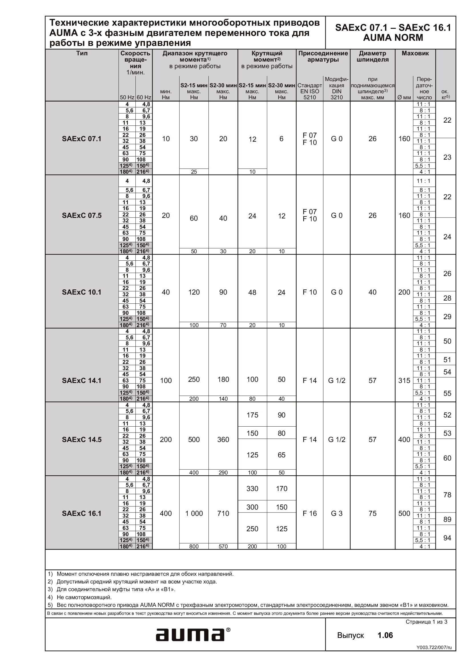
Multi-turn actuators SAExC 07.1 - 16.1, open-close duty, 3-phase AC
Technical data
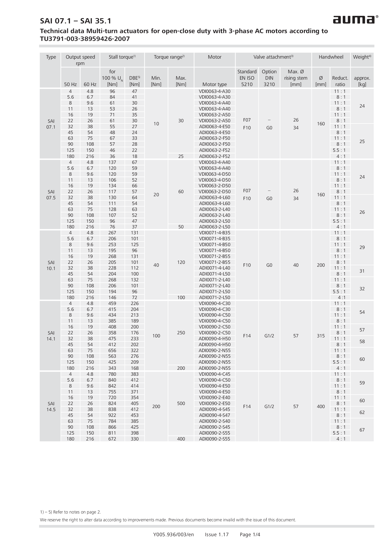
Multi-turn actuators SAI 07.1 - 35.1 , open-close duty, nuclear power plants, TU3791-003-38959426-2007
Technical data
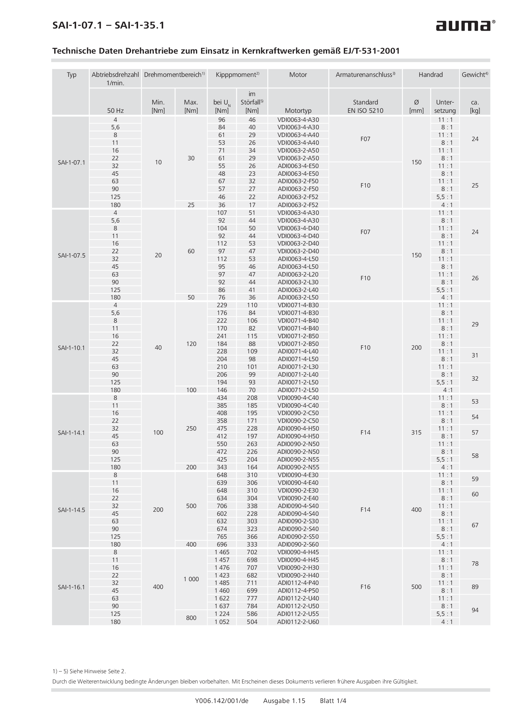
Multi-turn actuators SAI-1-07.1 - 35.1, open-close duty, nuclear power plants, EJ/T-531-2001
Technical data
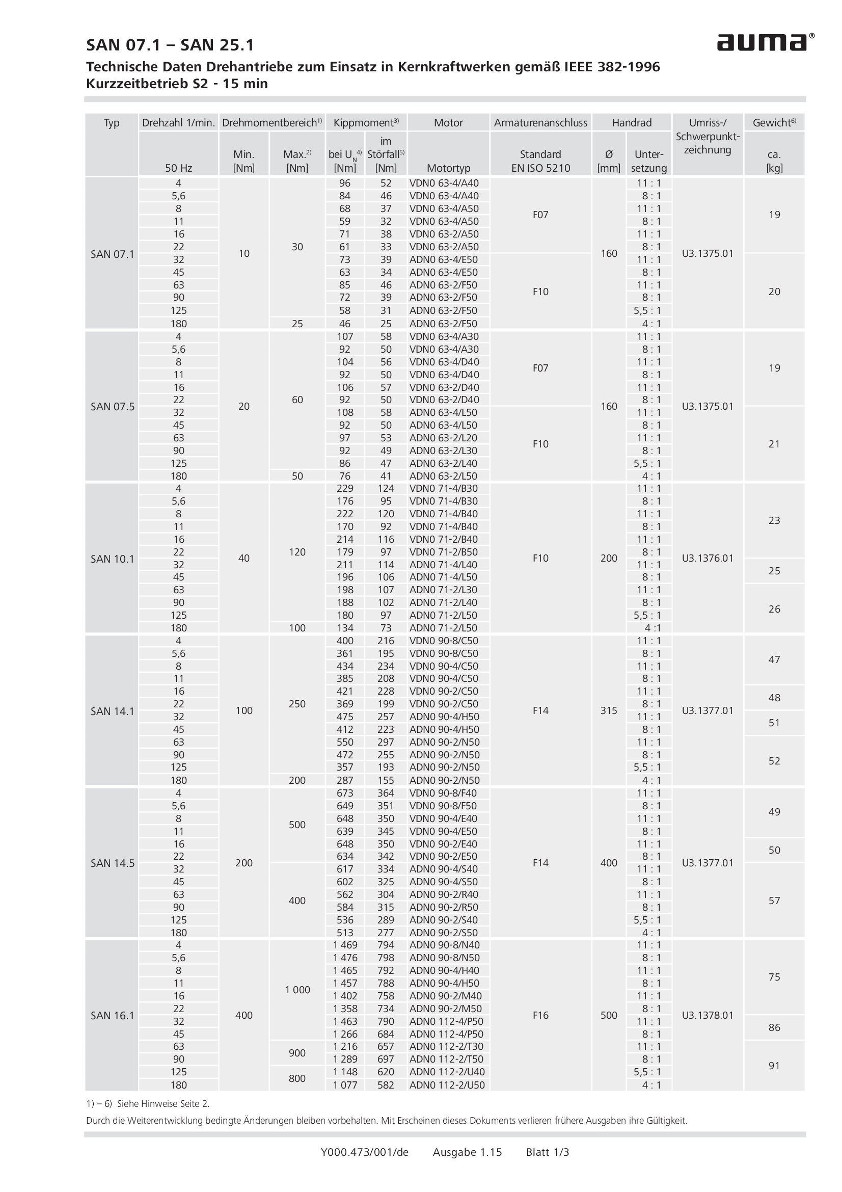
Multi-turn actuators SAN 07.1 - 25.1 , open-close duty, nuclear power plants, IEEE 382-1996
Technical data
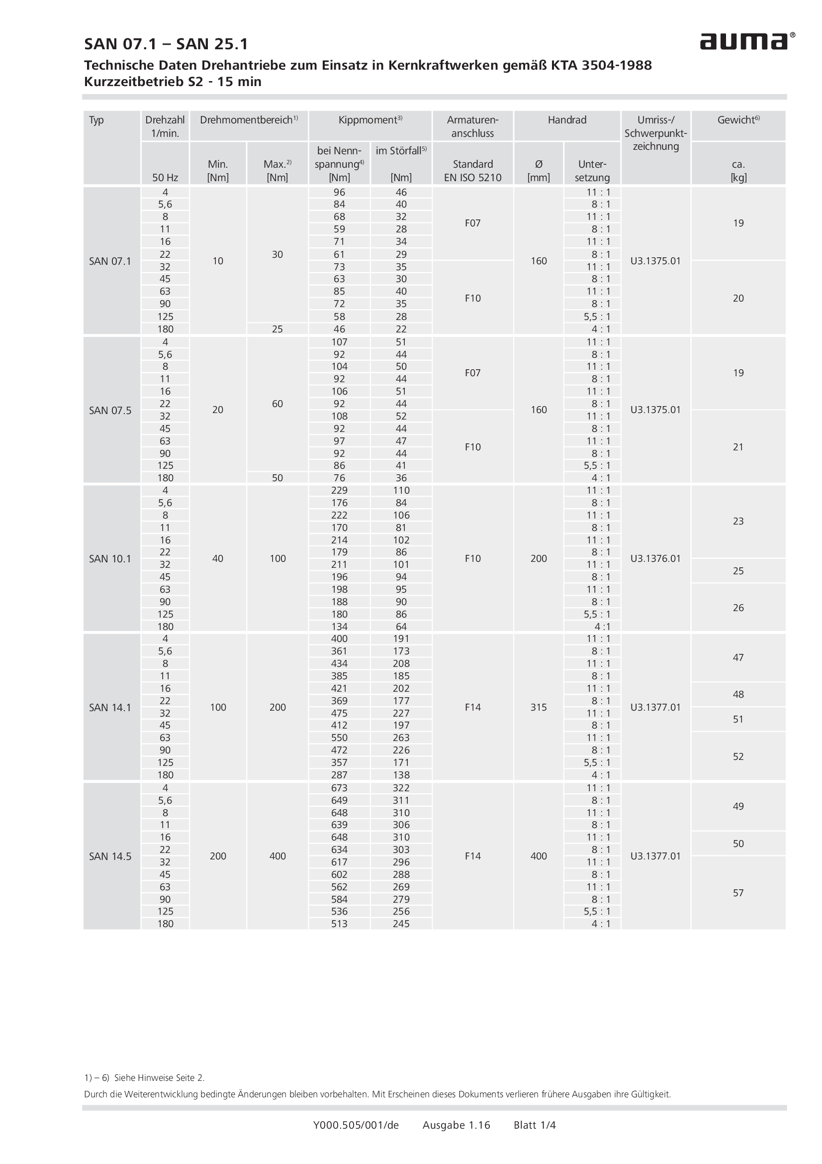
Multi-turn actuators SAN 07.1 - 25.1, open-close duty, nuclear power plants, KTA 3504-1988
Technical data

Multi-turn actuators SAN-1-07.1 - 35.1 , open-close duty, nuclear power plants, EJ/T-531-2001
Technical data

Multi-turn actuators SAR 07.1 - 14.5, modulating duty, DC
Technical data
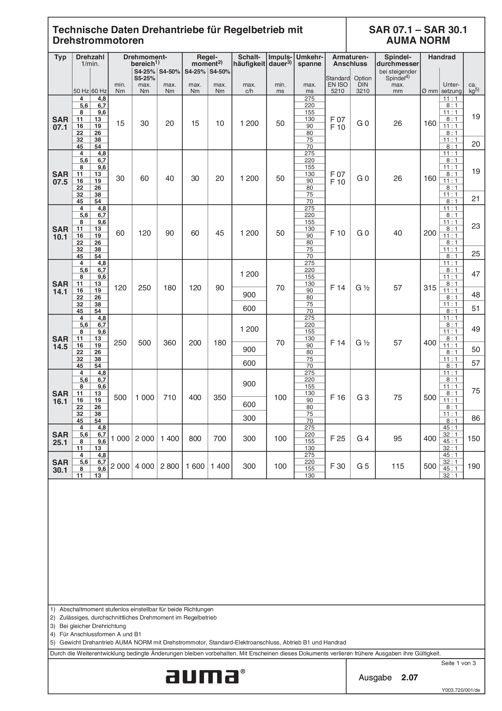
Multi-turn actuators SAR 07.1 - 30.1, modulating duty, 3-phase AC
Technical data

Multi-turn actuators SAR 07.2-UW - SAR 16.2-UW, modulatingn duty, 3-phase AC, for continuous underwater use
Technical data

Multi-turn actuators SAR 25.1-UW - SAR 30.1-UW, modulatingn duty, 3-phase AC, for continuous underwater use
Technical data

Multi-turn actuators SAREx 07.2-UW - SAREx 16.2-UW, modulatingn duty, 3-phase AC, for continuous underwater use
Technical data

Multi-turn actuators SARI 07.1 - 30.1 , modulating duty, nuclear power plants, TU3791-003-38959426-2007
Technical data

Multi-turn actuators SARV 07.2-UW - 16.2-UW, modulating duty, for continuous underwater use
Technical data

Multi-turn actuators SAV 07.2-UW - 16.2-UW, open-close duty, for continuous underwater duty
Technical data

Multi-turn actuators TR-M30X - M1000X, Torques for differential voltages, Short-time duty S2 - 15 min, Intermittent duty S4 -25 %
Technical data

Multi-turn actuators TR-M30X - M1000X, Torques for differential voltages, Short-time duty S2 - 30 min, Intermittent duty S4 -50 %
Technical data

Multi-turn gearboxes GP 10.1 – GP 30.1
Technical data

Multi-turn gearboxes GST 10.1 - 40.1
Technical data

Nuclear switches for actuators
Technical data
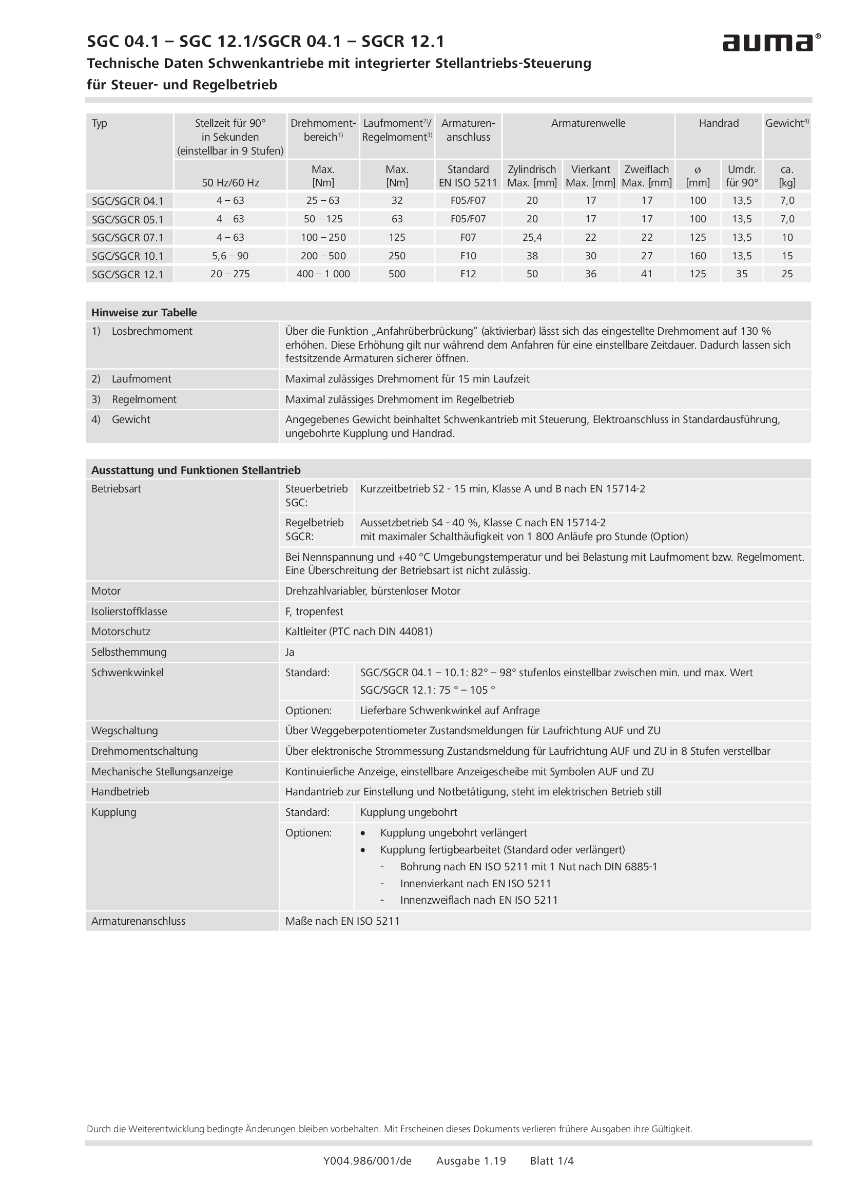
Part-turn actuators SGC/SGCR 04.1 - 12.1
Technical data
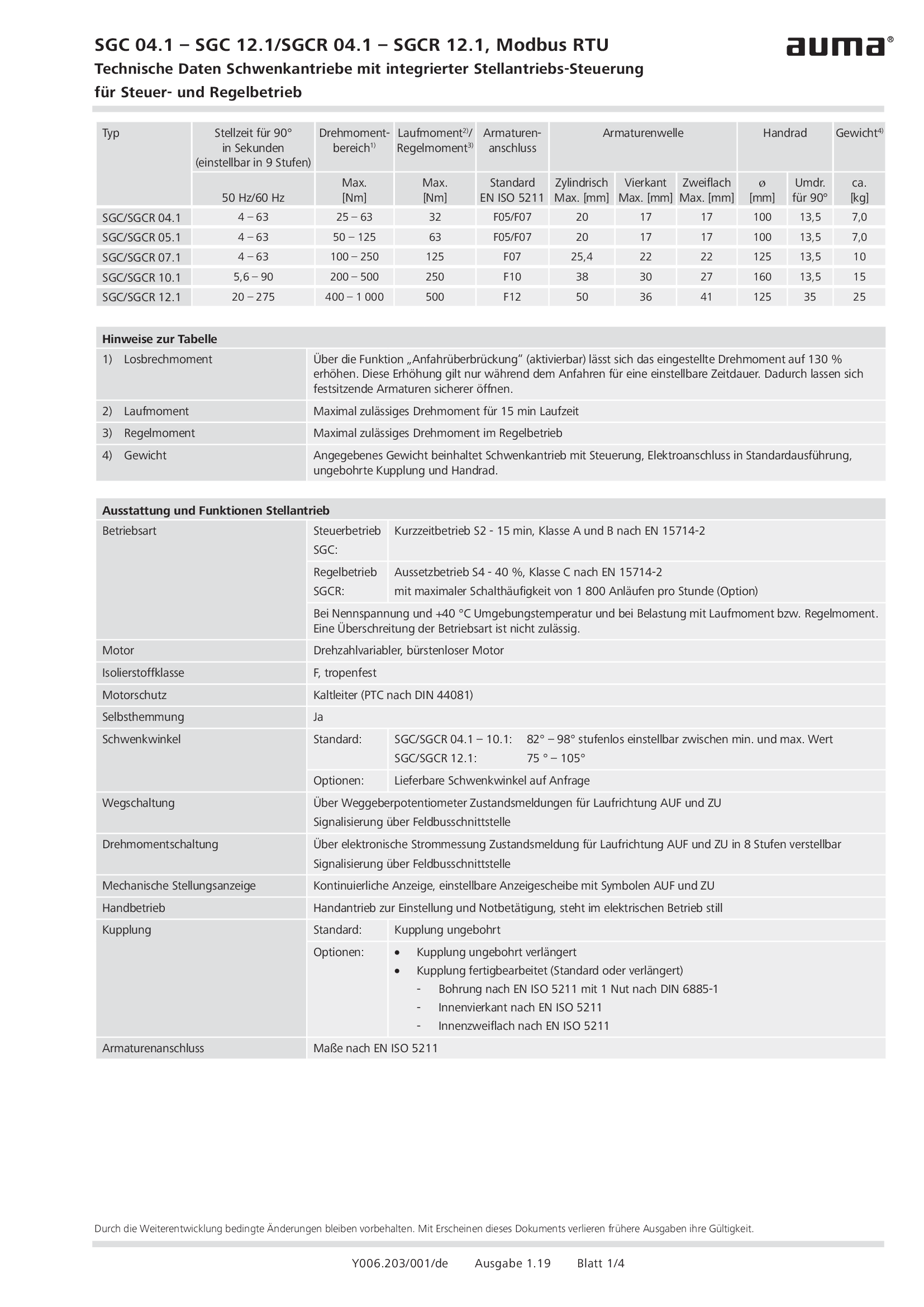
Part-turn actuators SGC/SGCR 04.1 - 12.1, Modbus RTU
Technical data

Part-turn actuators SGC/SGCR 04.1 - 12.1, Profibus DP
Technical data

Part-turn actuators SQ/SQR 05.2 - 14.2 / SQEx/SQREx 05.2 - 14.2, Torques for differential voltages, Short-time duty S2 - 15 min, Intermittent duty S4 - 25 %
Technical data
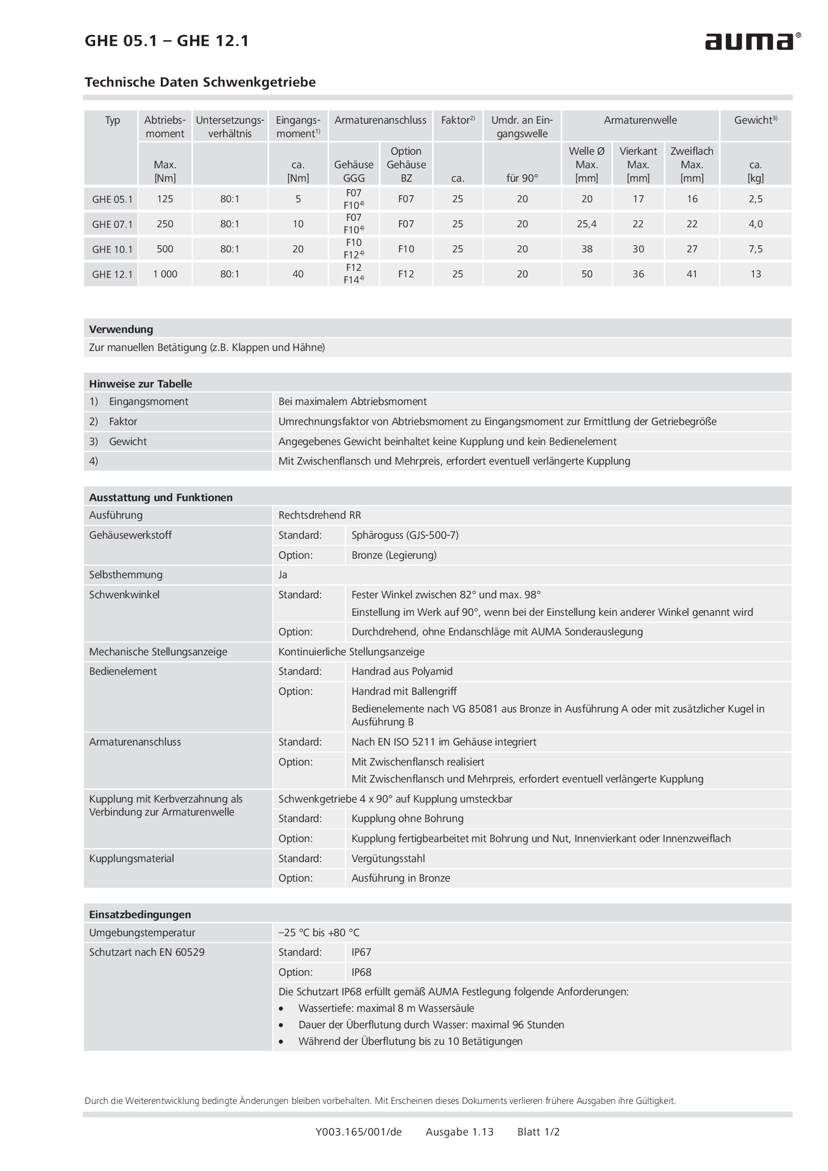
Part-turn gearboxes GHE 05.1 - 12.1
Technical data
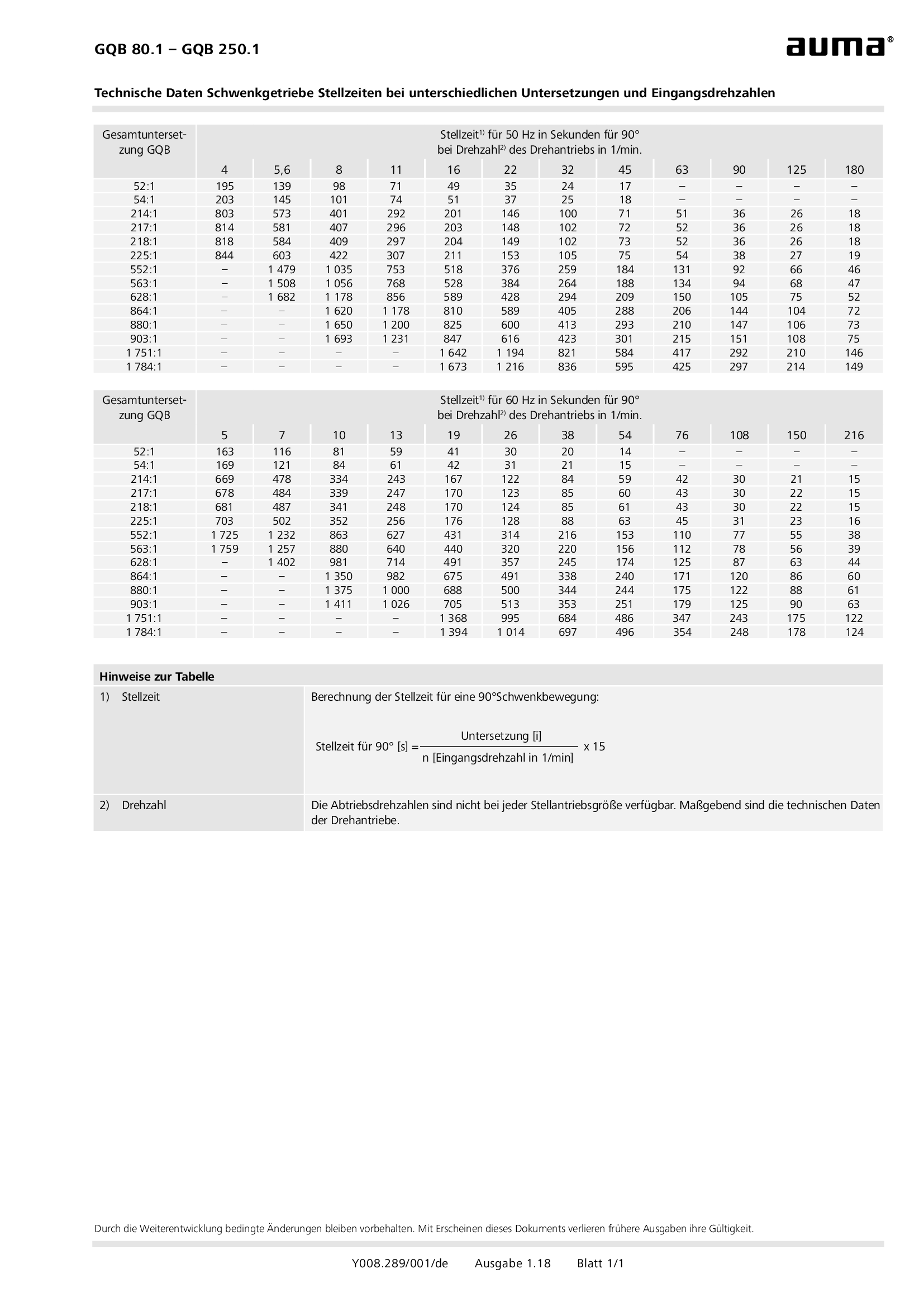
Part-turn gearboxes GQB 80.1 - 250.1 Operating times for different reduction ratios and input speeds
Technical data

Part-turn gearboxes GS 315 - 500, modulating duty and shorter operating time
Technical data
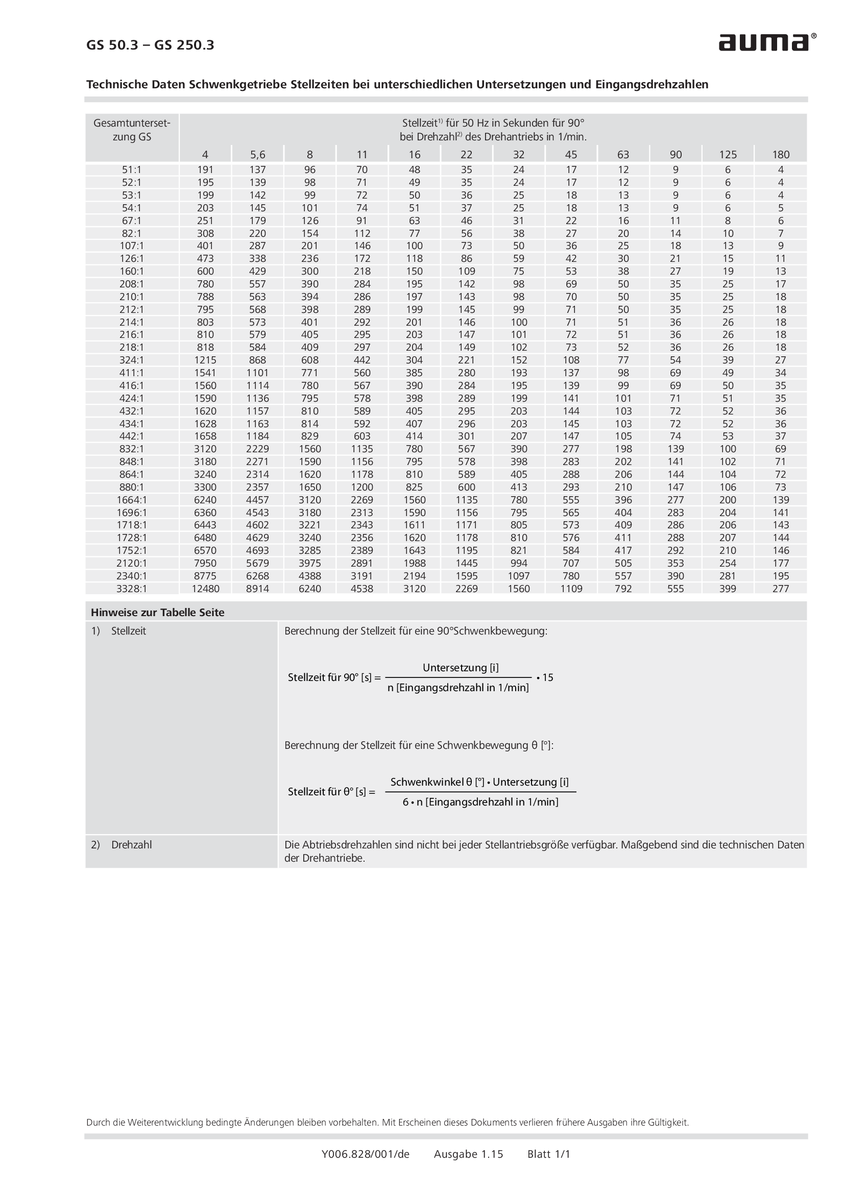
Part-turn gearboxes GS 50.3 - 250.3, Operating times for different reduction ratios and input speeds
Technical data
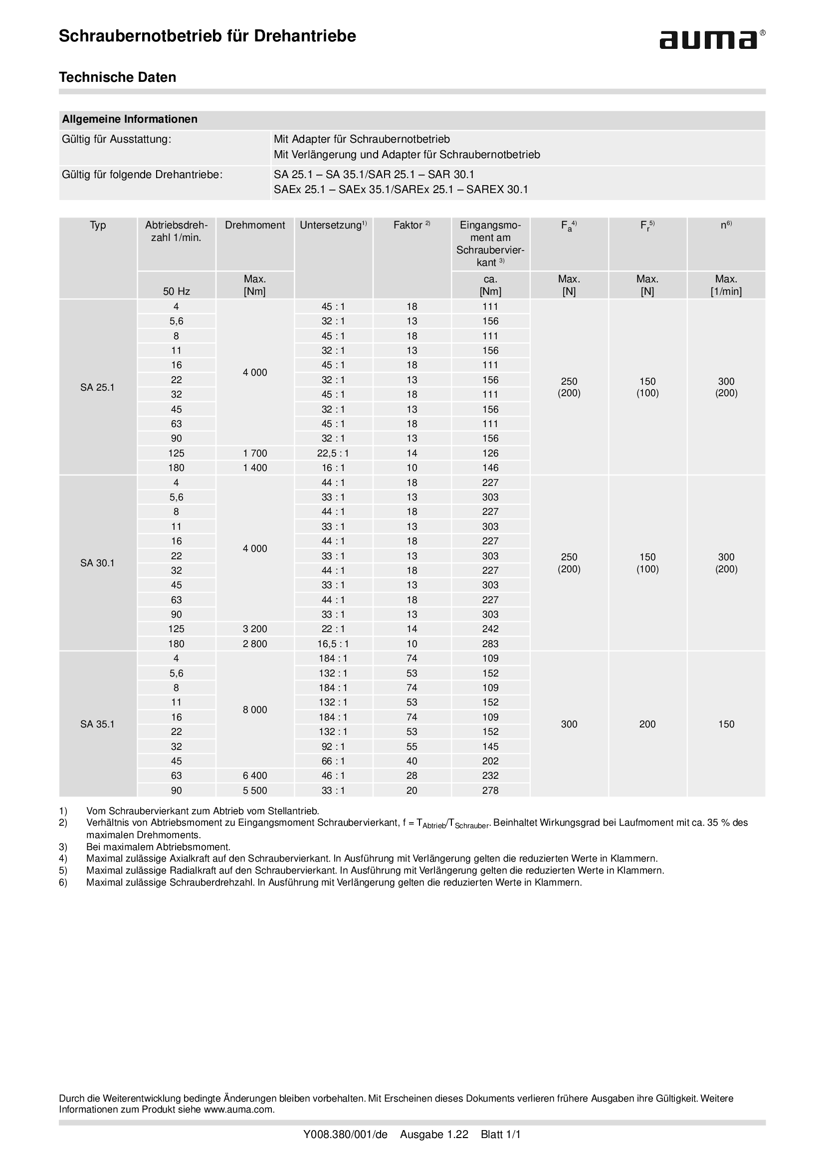
Power tool for emergency operation for multi-turn actuators SA .1
Technical data
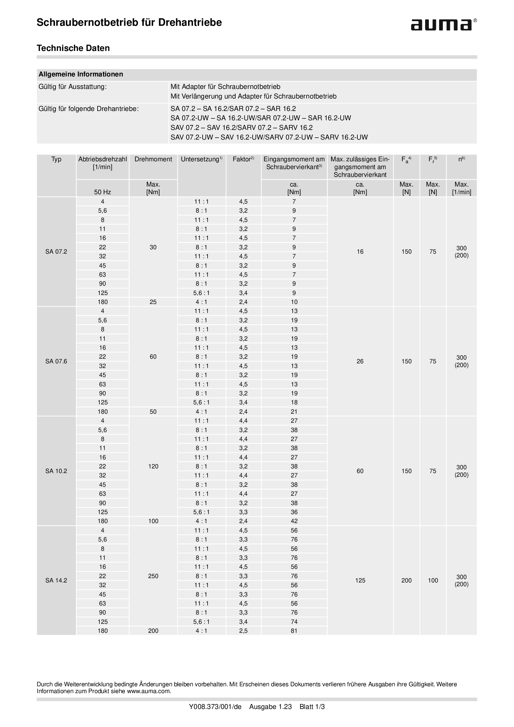
Power tool for emergency operation for multi-turn actuators SA .2
Technical data
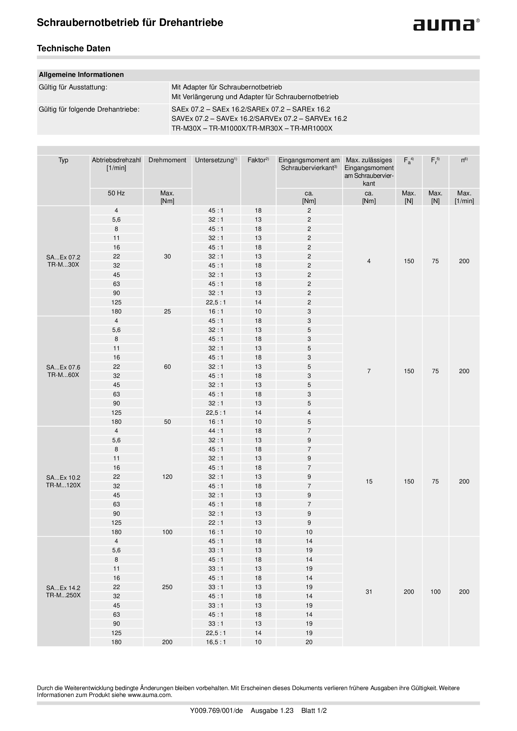
Power tool for emergency operation for multi-turn actuators SAEx .2 and TIGRON
Technical data
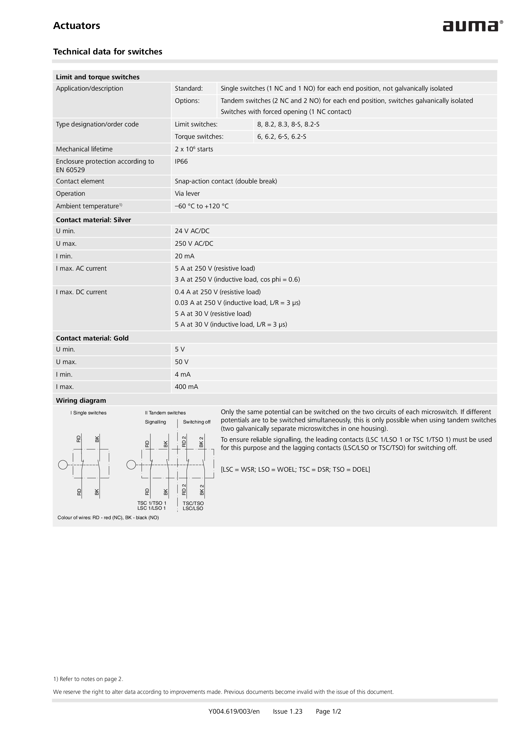
Switches for actuators
Technical data

Switches in flameproof enclosure for actuators
Technical data
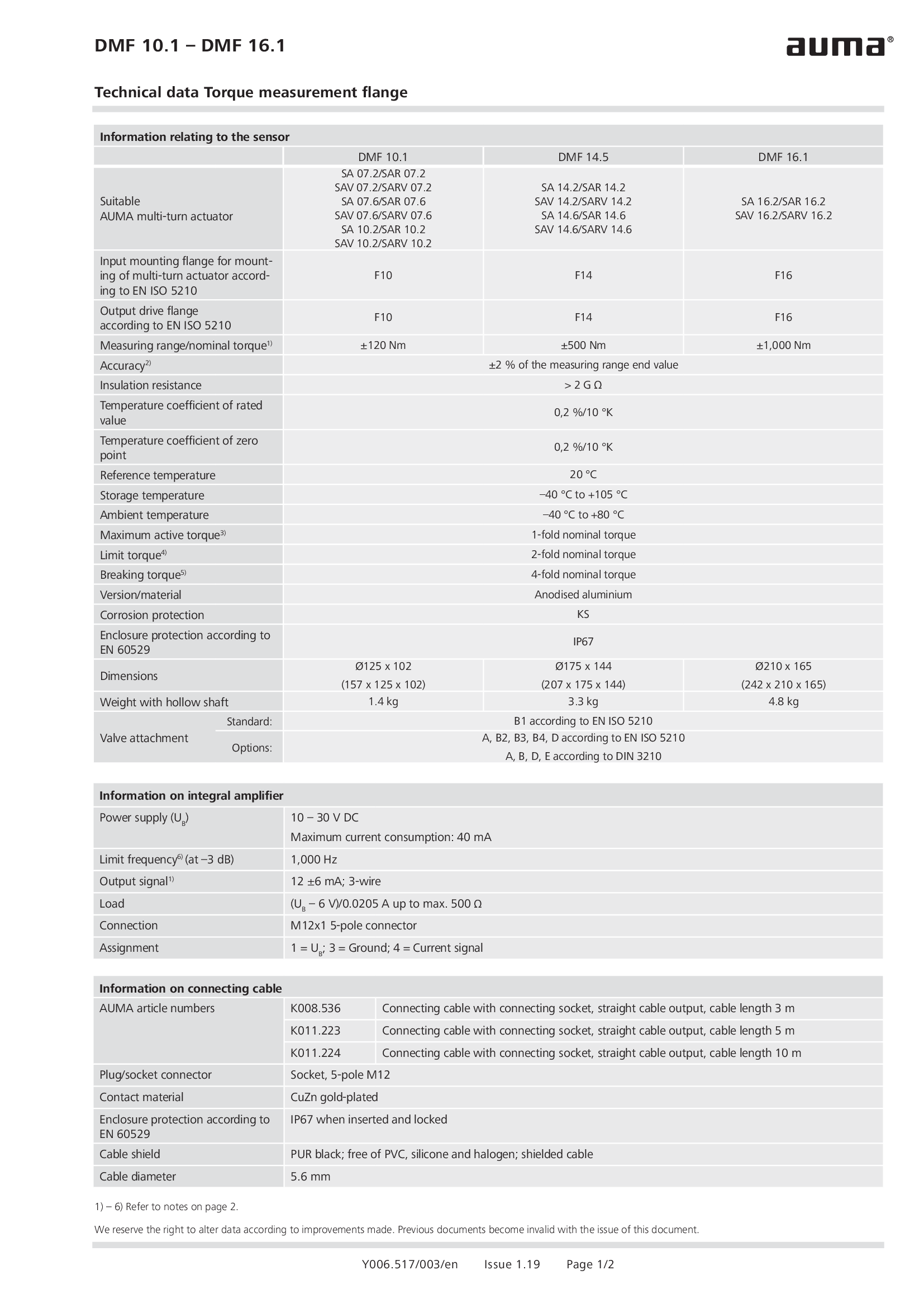
Torque measurement flange DMF 10.1 - 16.1
Technical data

Valve actuators SV 05.1 - 07.1 MEC 02.1
Technical data
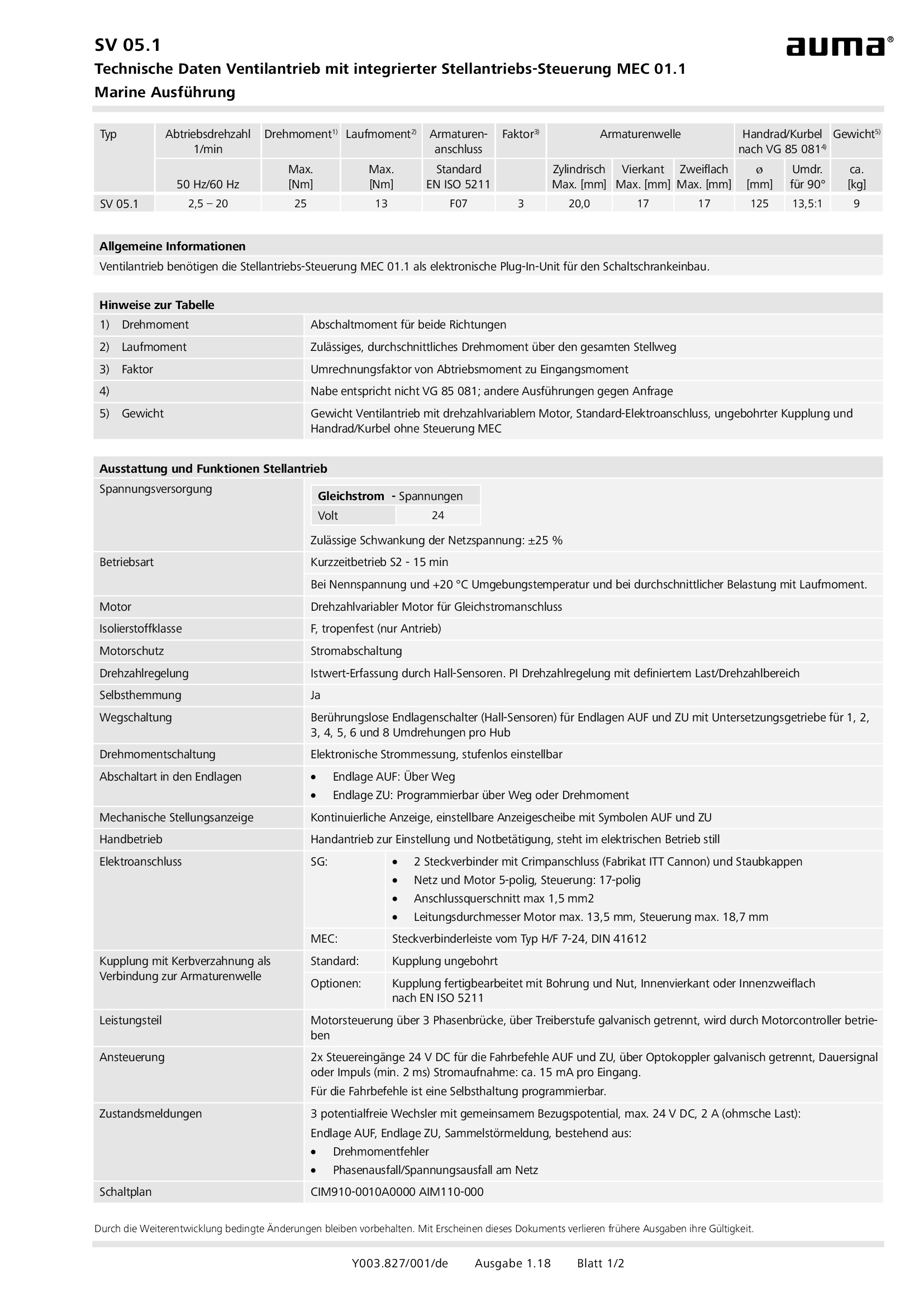
Valve actuators SV 05.1 - 07.1 MEC 02.1, military ship building (navy)
Technical data

Valve actuators SV 05.1 - 07.1 MEC 03.1
Technical data

Valve actuators SVC/SVCR 05.1 - 07.5
Technical data

Valve actuators SVC/SVCR 05.1 - 07.5, Modbus RTU
Technical data

Valve actuators SVC/SVCR 05.1 - 07.5, Profibus DP
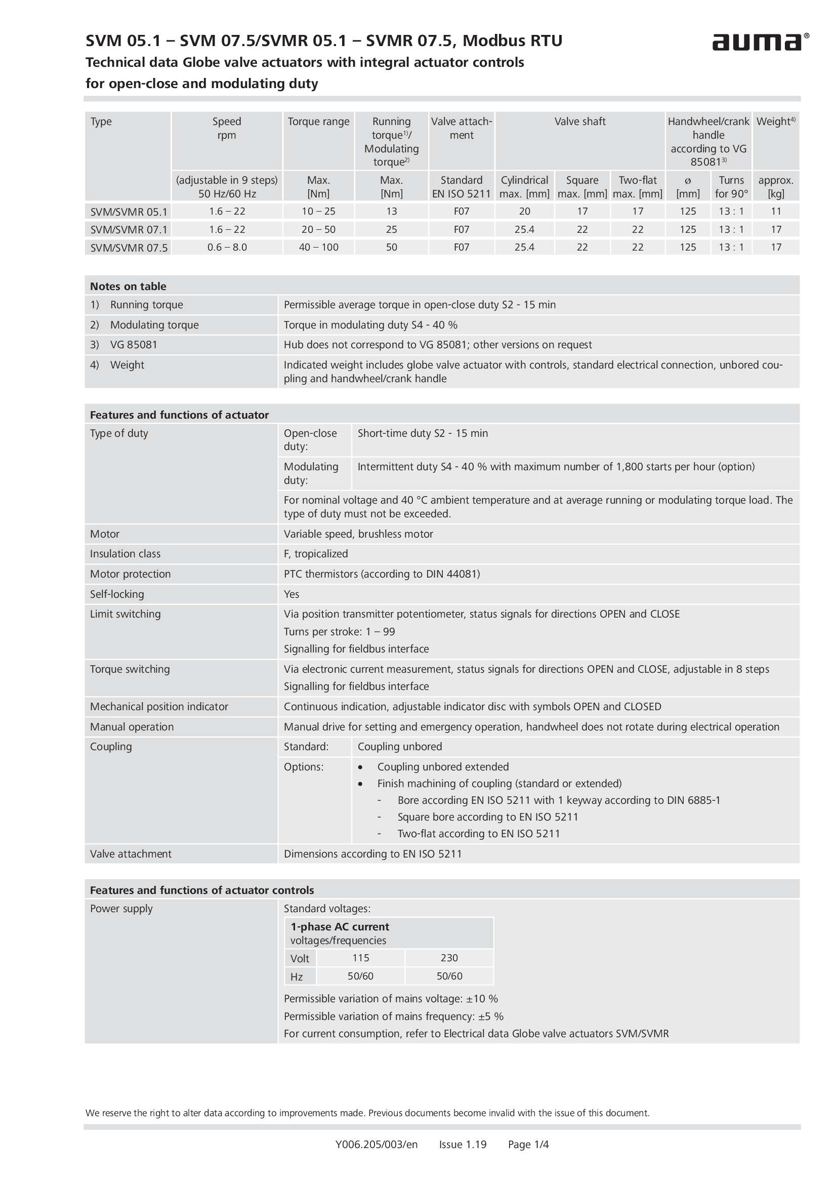
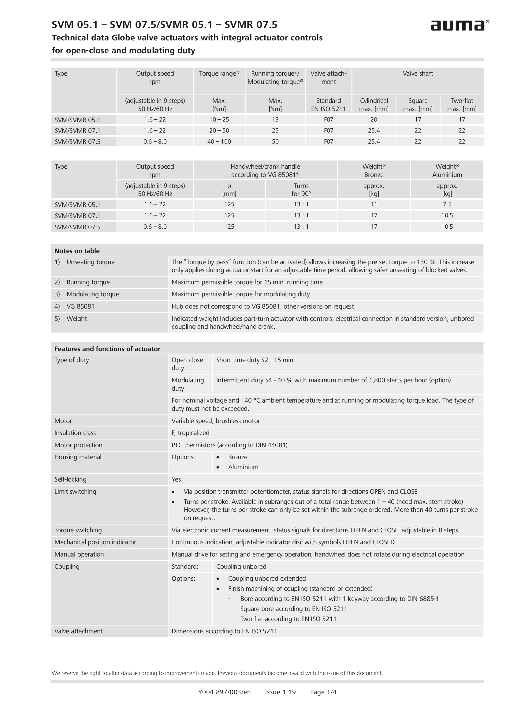
Technical data
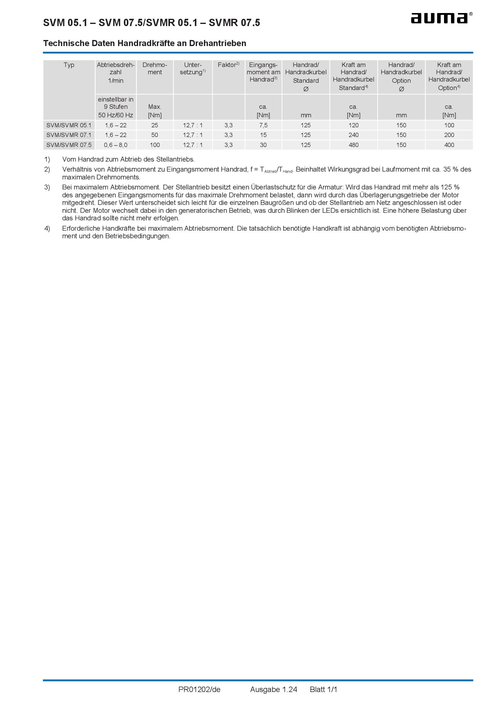
Valve actuators SVM/SVMR 05.1 - 07.5, Handwheel forces
Technical data
Valve actuators SVM/SVMR 05.1 - 07.5, Modbus RTU, military ship building (navy)
Technical data

Valve actuators SVM/SVMR 05.1 - 07.5, Profibus DP, military ship building (navy)
Technical data
Valve actuators SVM/SVMR 05.1 - 07.5, military ship building (navy)
Technical data
Technical description
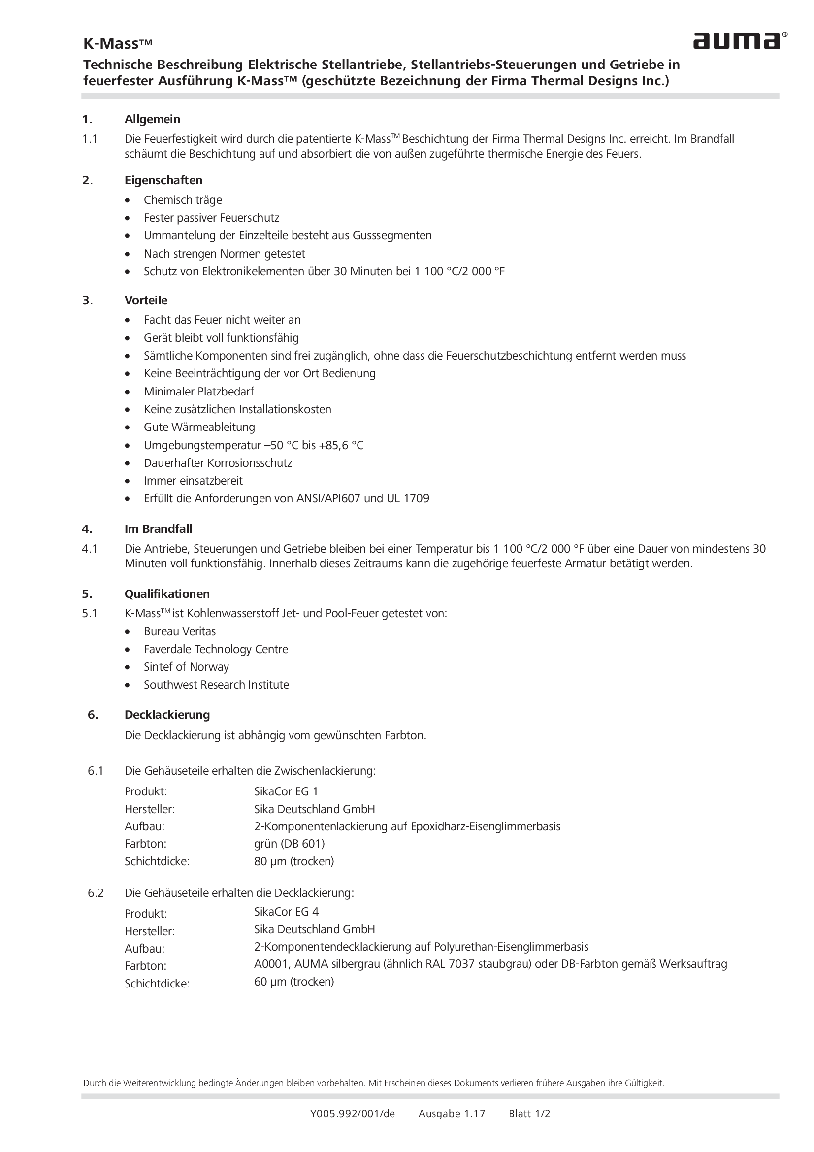
Coating for actuators, actuator controls and gearboxes in fireproof version K-Mass
Technical description
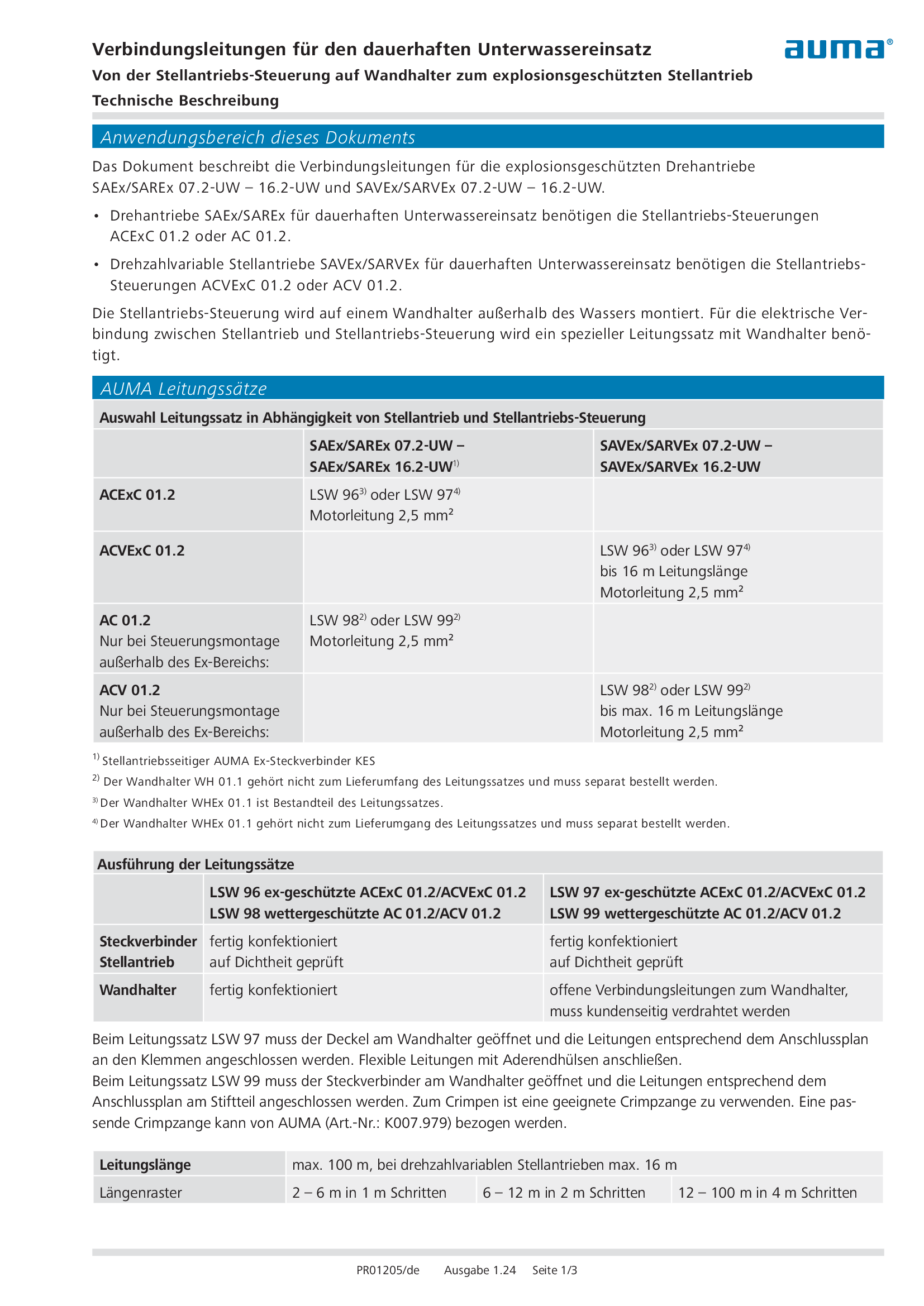
Connecting cable for continuous underwater use (explosion-proof actuator)
Technical description
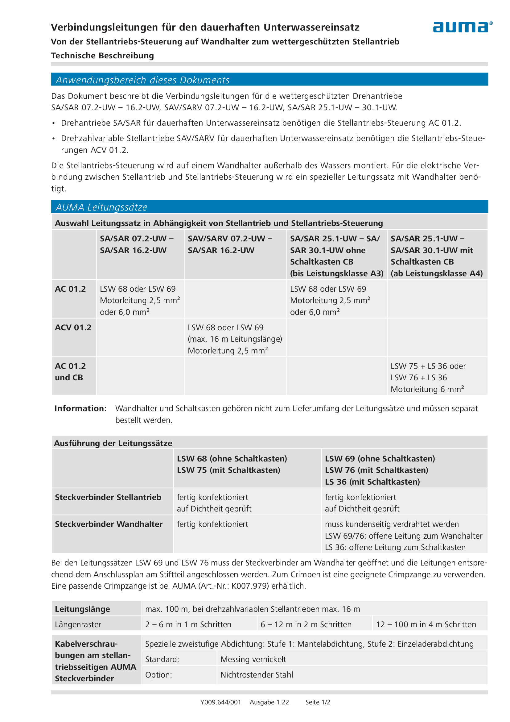
Connecting cable for continuous underwater use (weatherproof actuator)
Technical description
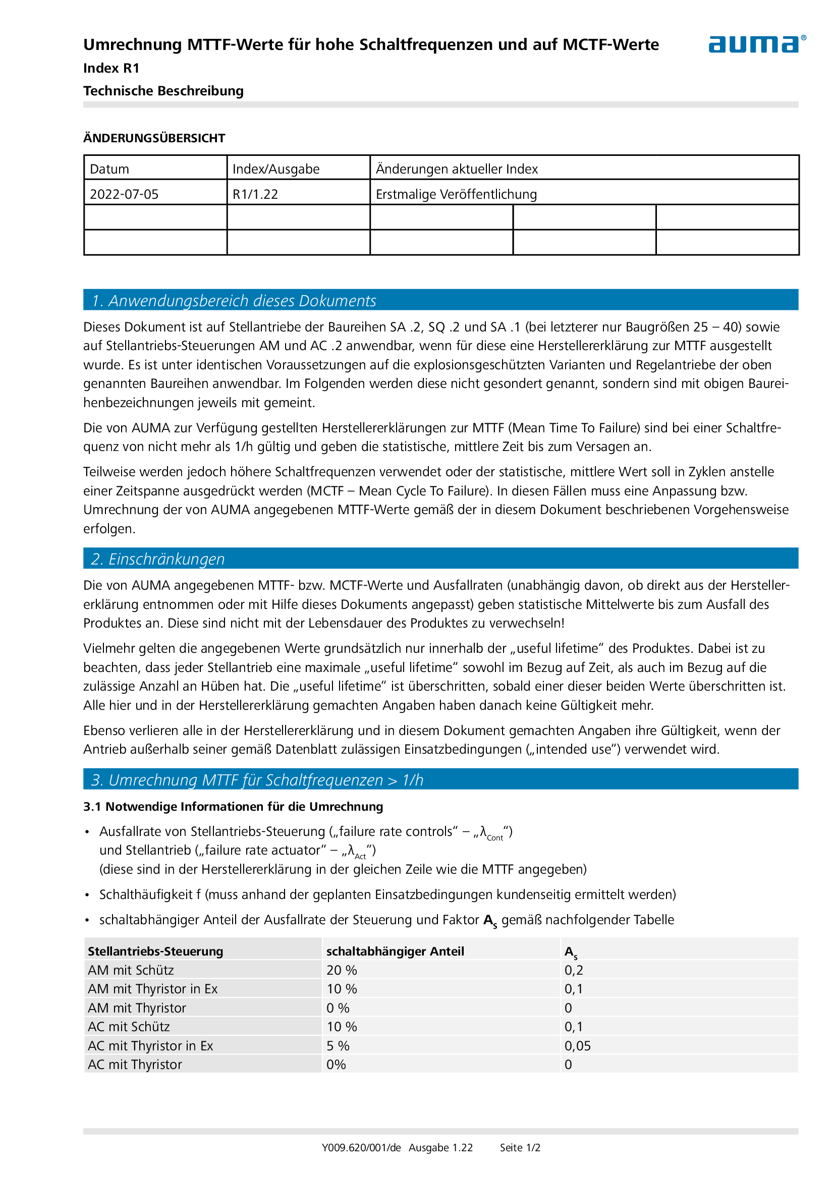
Conversion of MTTF values for high numbers of starts and to MCTF values
Technical description
Corrosion protection KX according LV P1.001 for SAUDI ARAMCO Projects
Technical description
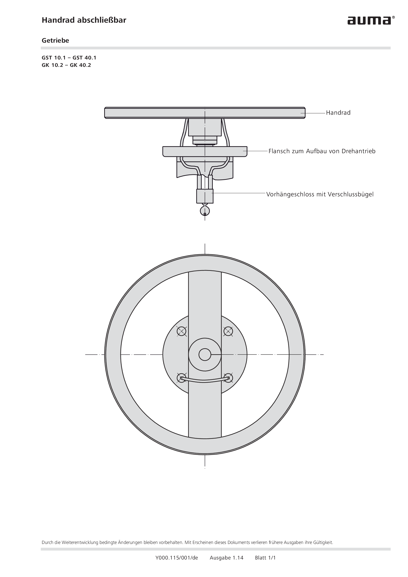
Handwheel lockable gearboxes GST 10.1 – GST 40.1, GK 10.2 – GK 40.2
Technical description
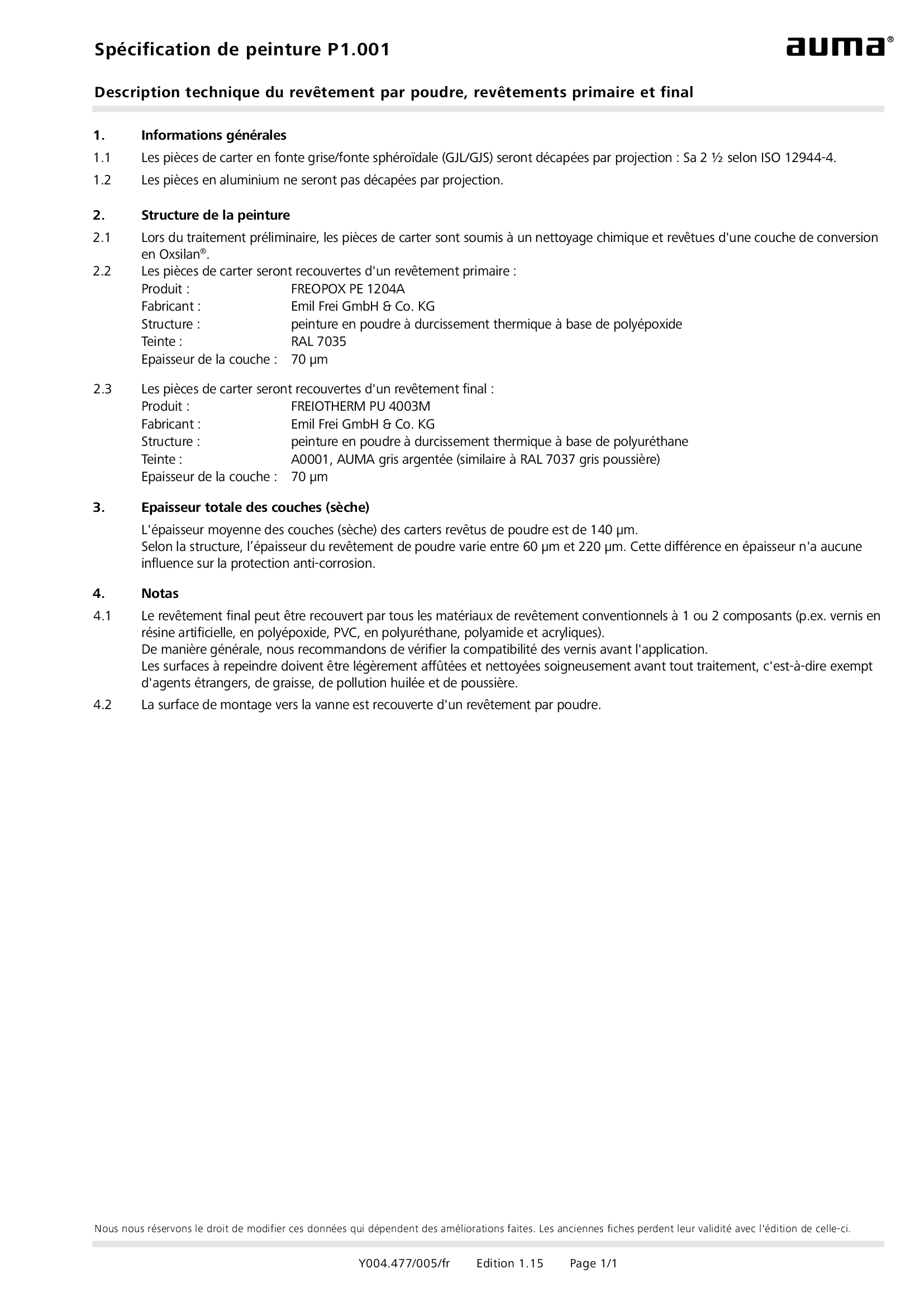
Painting specification P1.001 Powder coating, primer coating and finsh coating
Technical description
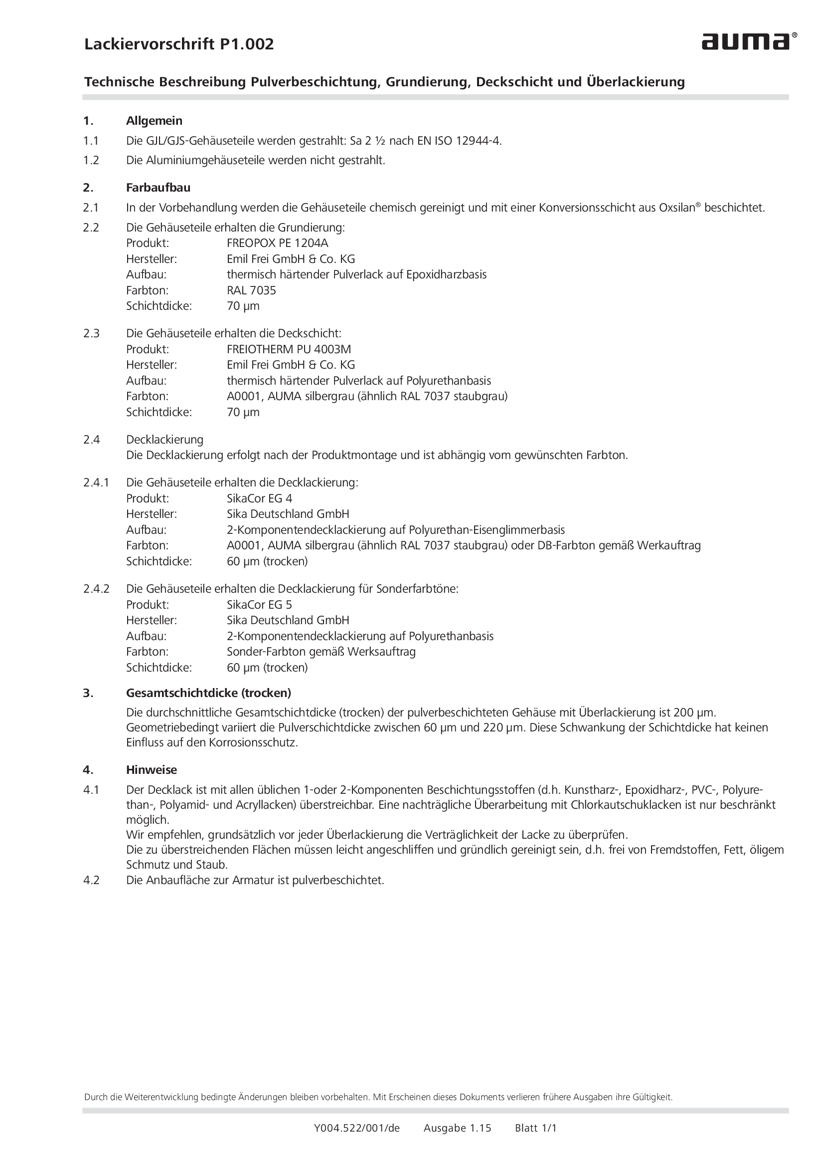
Painting specification P1.002 Powder coating, primer coating, finish coating and additional painting
Technical description
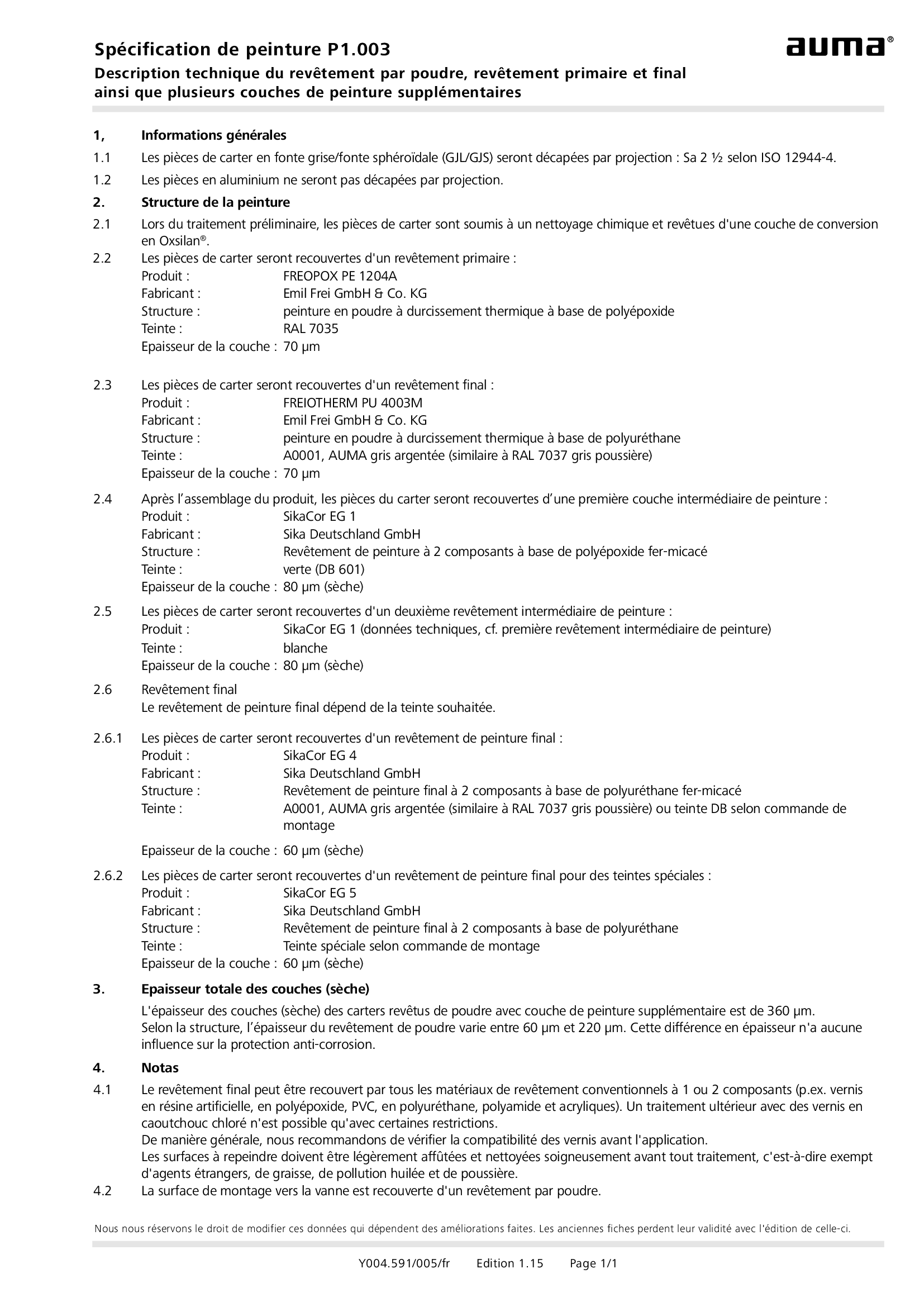
Painting specification P1.003 Powder coating, primer coating, finish coating and multi-layer painting
Technical description
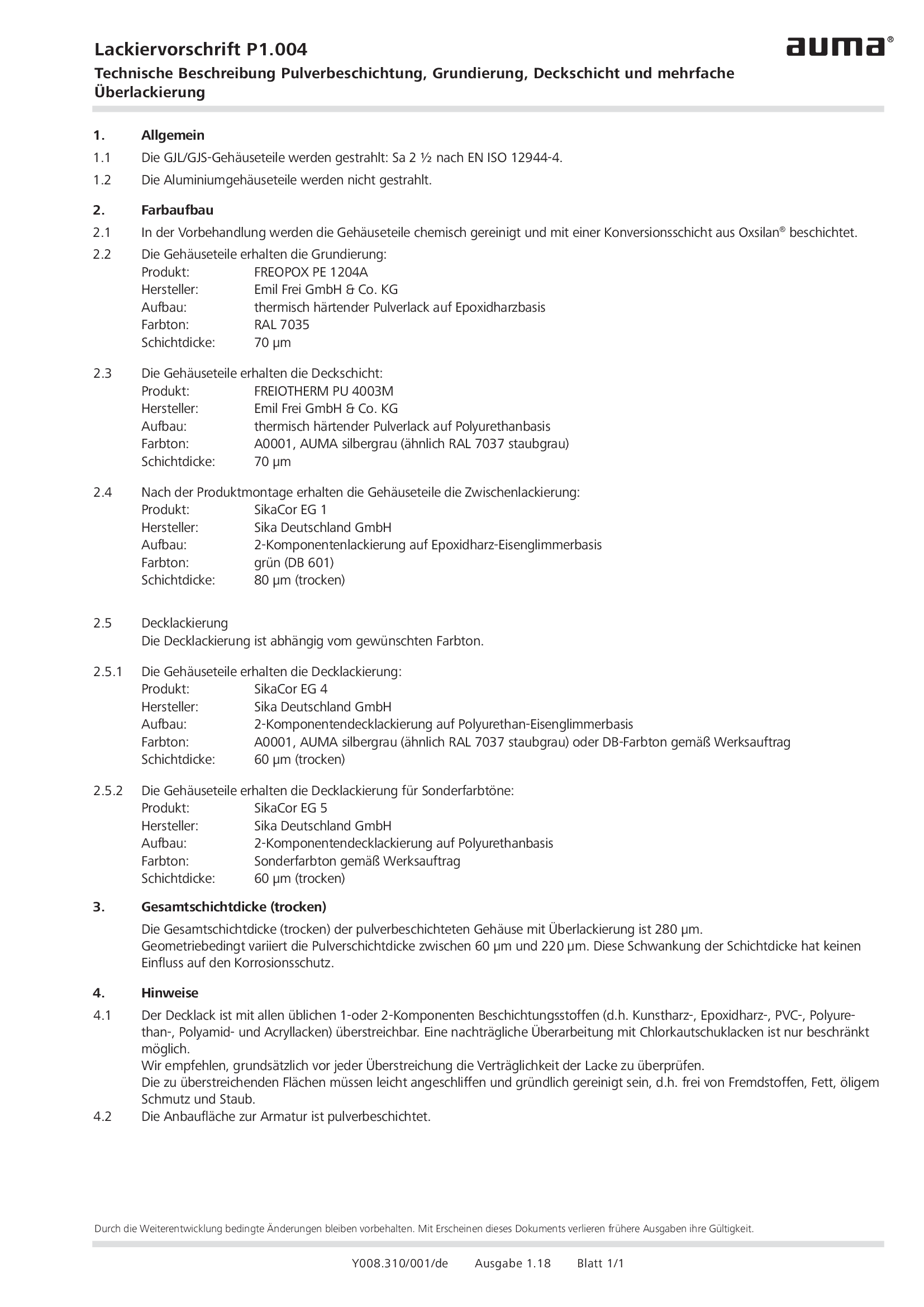
Painting specification P1.004 Powder coating, primer coating, finish coating and multi-layer painting
Technical description
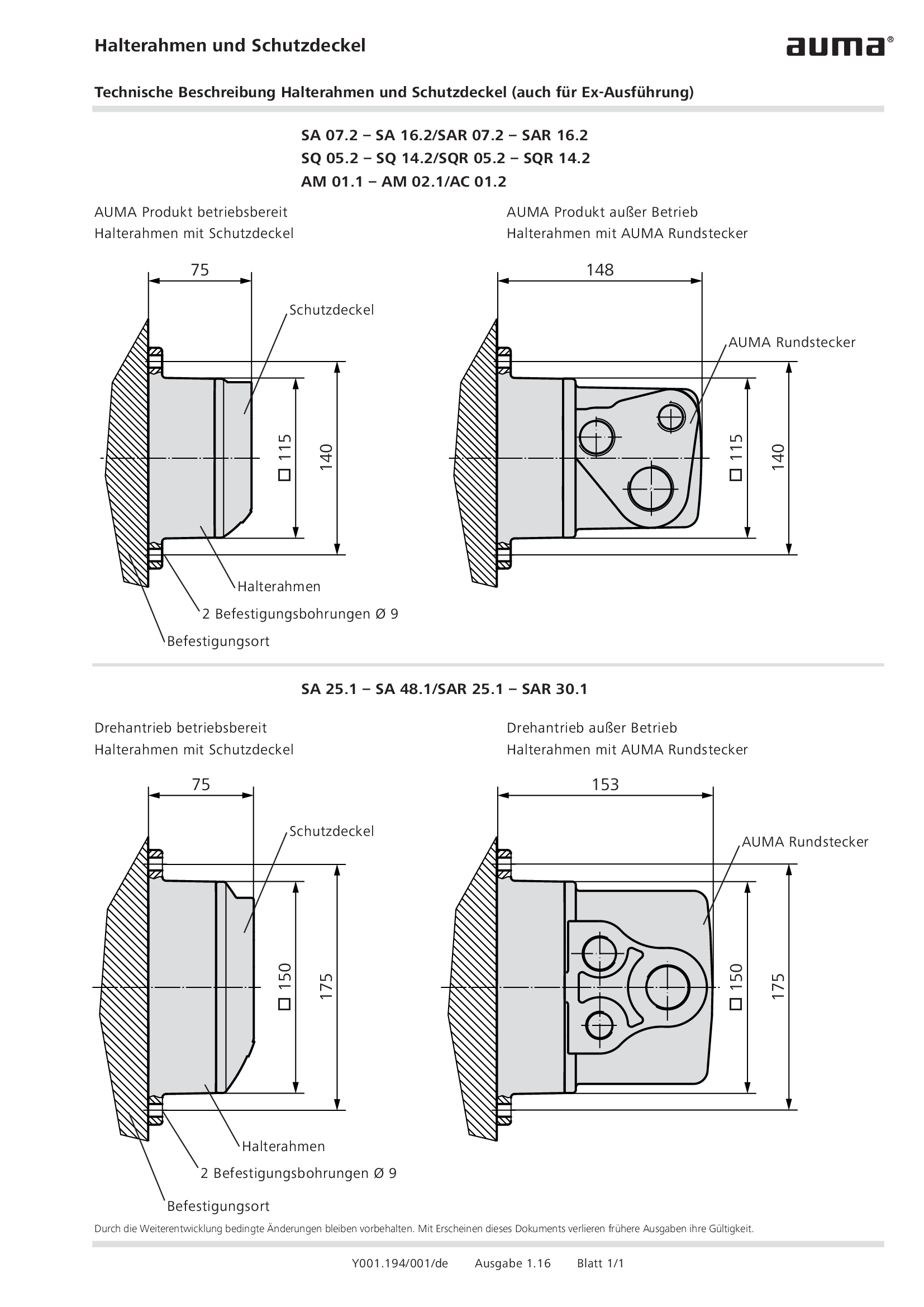
Parking frame and protection cover
Technical description
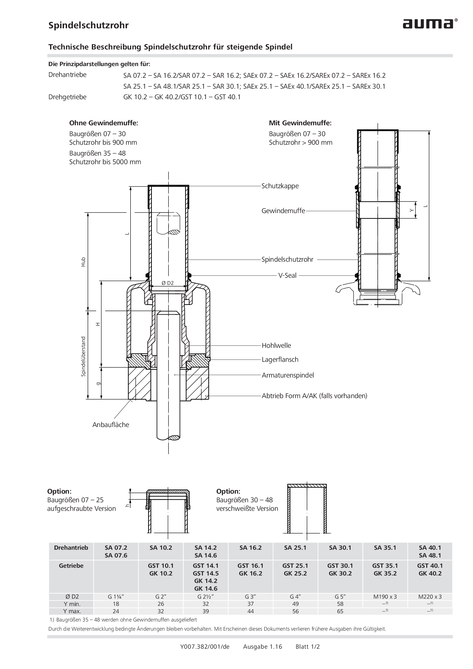
Stem protection tube for rising stem
Technical description
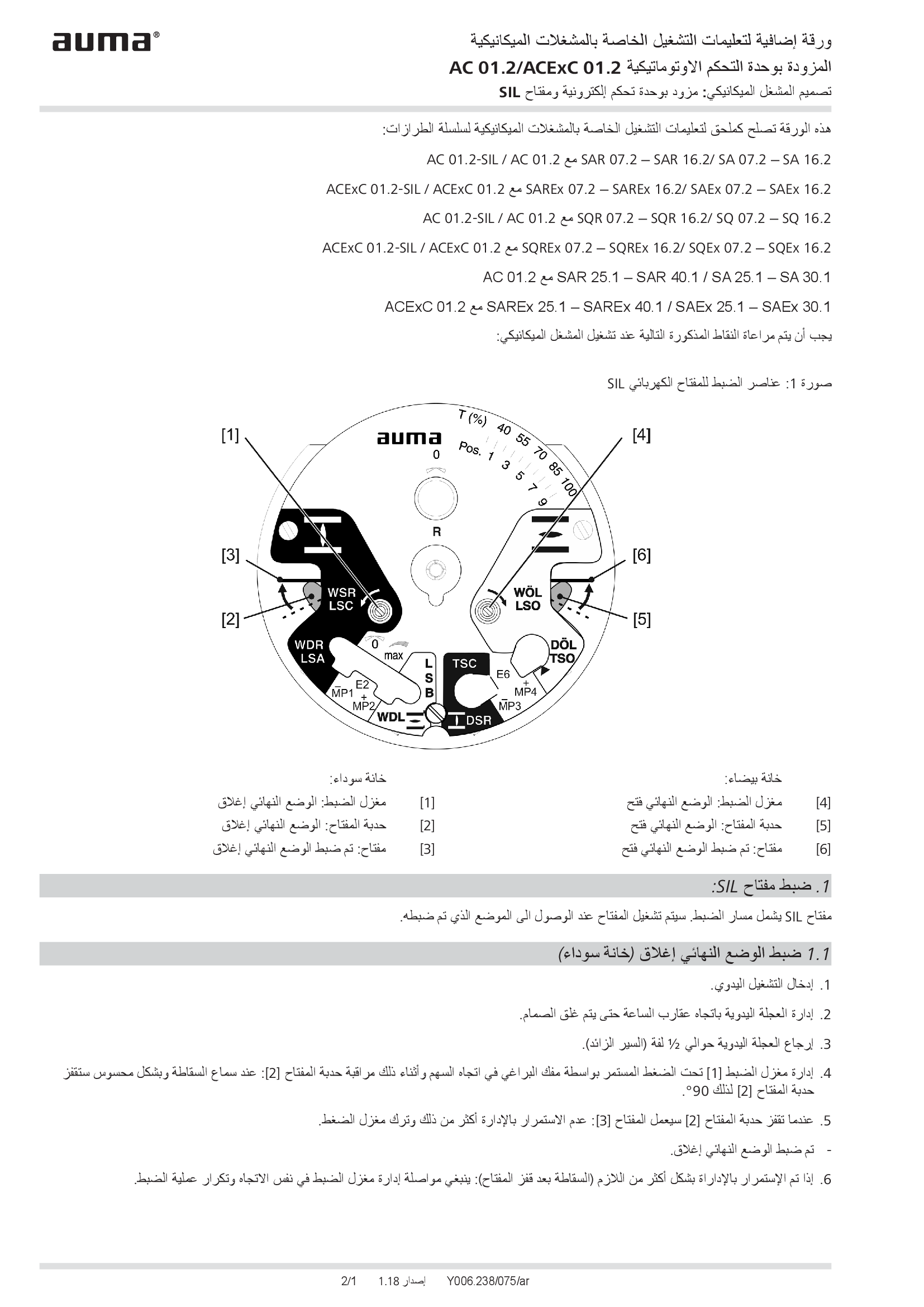
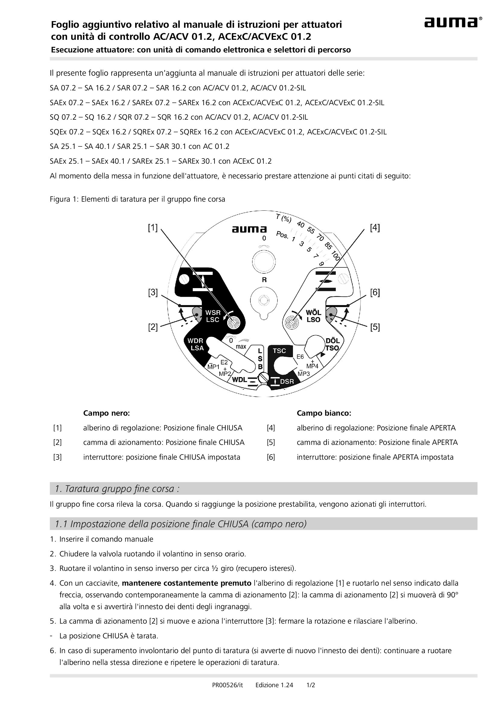
Supplement AUMATIC AC 01.2/ACExC 01.2, version actuators: with elektronic control unit (MWG) and SIL limit switching
Technical description
Supplement AUMATIC AC 01.2/ACExC 01.2, version actuators: with elektronic control unit (MWG) and limit switching
Technical description
Wiring diagram

A2: AUMATIC AC 01.2 positioner and postition feedback signal 0/4 - 20 mA (potentiometer in actuator), reversing contactors OPEN, STOP, CLOSE, EMERGENCY, MODE (24 V DC), 6 programmable output contacts, AUMA power class A1 - A3
Wiring diagram

A2: AUMATIC ACExC 01.2 positioner and position feedback signal 0/4 - 20 mA (potentiometer in actuator), reversing contactors MODE, CLOSE, OPEN, STOP, EMERGENCY (24 V DC), setpoint (0/4 - 20 mA), 6 programmable output contacts, AUMA power class A1 -
Wiring diagram

A2N: AUMATIC AC 01.2 positioner and position/torque feedback signal 0/4 - 20 mA (MWG in actuator), , reversing contactors OPEN, STOP, CLOSE, EMERGENCY, MODE (24 V DC), 6 programmable output contacts, AUMA power class A1 - A3
Wiring diagram

A2N: AUMATIC ACExC 01.2 positioner and position/torque feedback signal 0/4 - 20 mA (MWG in actuator), reversing contactors MODE, CLOSE, OPEN, STOP, EMERGENCY (24 V DC), 6 programmable output contacts, AUMA power class A1 - A3
Wiring diagram

A3: AUMATIC AC 01.2 positioner and position feedback signal 0/4 - 20 mA (potentiometer in actuator), thyristors OPEN, STOP, CLOSE, EMERGENCY, MODE (24 V DC), 6 programmable output contacts, AUMA power class B1/B2
Wiring diagram

A3: AUMATIC AC 01.2 positioner and position feedback signal 0/4 - 20 mA (potentiometer in actuator), thyristors OPEN, STOP, CLOSE, EMERGENCY, MODE (24 V DC), 6 programmable output contacts, AUMA power class B3
Wiring diagram

A3: AUMATIC ACExC 01.2 positioner and position feedback signal 0/4 - 20 mA (potentiometer in actuator), thyristors MODE, CLOSE, OPEN, STOP, EMERGENCY (24 V DC), setpoint (0/4 - 20 mA) 6 programmable output contacts, AUMA power class B1/B2
Wiring diagram

A3: AUMATIC ACExC 01.2 positioner and position feedback signal 0/4 - 20 mA (potentiometer in actuator), thyristors MODE, CLOSE, OPEN, STOP, EMERGENCY (24 V DC), setpoint (0/4 - 20 mA) 6 programmable output contacts, AUMA power class B3
Wiring diagram

A3N: AUMATIC AC 01.2 positioner and position/torque feedback signal 0/4 - 20 mA (MWG in actuator), thyristors OPEN, STOP, CLOSE, EMERGENCY, MODE (24 V DC), 6 programmable output contacts, AUMA power class B1/B2
Wiring diagram

A3N: AUMATIC AC 01.2 positioner and position/torque feedback signal 0/4 - 20 mA (MWG in actuator), thyristors OPEN, STOP, CLOSE, EMERGENCY, MODE (24 V DC), 6 programmable output contacts, AUMA power class B3
Wiring diagram

A3N: AUMATIC ACExC 01.2 positioner and position/torque feedback signal 0/4 - 20 mA (MWG in actuator), thyristors MODE, CLOSE, OPEN, STOP, EMERGENCY (24 V DC), setpoint (0/4 - 20 mA), 6 programmable output contacts, AUMA power class B1/B2
Wiring diagram

A3N: AUMATIC ACExC 01.2 positioner and position/torque feedback signal 0/4 - 20 mA (MWG in actuator), thyristors MODE, CLOSE, OPEN, STOP, EMERGENCY (24 V DC), setpoint (0/4 - 20 mA), 6 programmable output contacts, AUMA power class B3
Wiring diagram

A4DP: AUMATIC AC 01.2 positioner and position feedback signal 0/4 - 20 mA (potentiometer in actuator),basic version, reversing contactors MODE, CLOSE, OPEN, STOP, EMERGENCY, I/O (24 V DC), Profibus DP, AUMA power class A1 - A3
Wiring diagram

A4DP: AUMATIC ACExC 01.2 positioner and position feedbacck signal 0/4 - 20 mA (potentiometer in actuator), basic version, reversing contactors MODE, CLOSE, OPEN, STOP, EMERGENCY, I/O (24 V DC), 6 programmable output contacts, Profibus, power class A
Wiring diagram

A4ENIP: AUMATIC AC 01.2 positioner and position feedback signal 0/4 - 20 mA (potentiometer in actuator), basic version, reversing contactors MODE, CLOSE, OPEN, STOP, EMERGENCY, I/O (24 V DC), 6 programmable output contacts Ethernet/IP, AUMA power class
Wiring diagram

A4ENIP: AUMATIC ACExC 01.2 positioner and position feedback signal 0/4 - 20 mA (poti in actuator), basic version, reversing contactors MODE, CLOSE, OPEN, STOP, EMERGENCY, I/O (24 V DC), 6 programmable output contacts, EtherNet/IP, AUMA power class A1-A3
Wiring diagram

A4FF: AUMATIC AC 01.2 positioner and position feedback signal 0/4 – 20 mA (potentiometer in actuator), basic version, Reversing contactors MODE, CLOSE, OPEN, STOP, EMERGENCY, I/O (24V DC), 6 programmable output contacts, FF, AUMA power classes A1-A3
Wiring diagram

A4FF: AUMATIC ACExC 01.2 positioner and position feedback signal 0/4-20 mA (poti in actuator), basic version, reversing contactors MODE, CLOSE, OPEN, STOP, EMERGENCY, I/O (24 V DC),6 prorammable output contact, Foundation Fieldbus, AUMA power class A1-A3
Wiring diagram

A4HRT: AUMATIC AC 01.2 positioner and position feedback signal 0/4-20mA (potentiometer in actuator), basic version, Reversing contactors MODE, CLOSE, OPEN, STOP, EMERGENCY, I/O (24V DC), 6 programmable output contacts, HART, AUMA power classes A1 – A3
Wiring diagram

A4HRTCO: AUMATIC AC 01.2 positioner and position feedback signal 0/4-20mA (potentiometer in actuator), basic version, Reversing contactors MODE, CLOSE, OPEN, STOP, EMERGENCY, I/O (24V DC), 6 programmable output contacts, HART, AUMA power classes A1-A3
Wiring diagram

A4MB: AUMATIC AC 01.2 positioner and position feedback signal 0/4 - 20 mA (potentiometer in actuator), basic version, reversing contactors MODE, CLOSE, OPEN, STOP, EMERGENCY, I/O (24 V DC), 6programmable output contacts, Modbus RTU, power class A1 - A3
Wiring diagram

A4MB: AUMATIC ACExC 01.2 positioner and position feedback signal 0/4 - 20 mA (potentiometer in actuator), basic version, reversing contactors MODE, CLOSE, OPEN, STOP, EMERGENCY, I/O(24 V DC), 6 programmable output contacts, Modbus, AUMA power class
Wiring diagram

A4N: AUMATIC AC 01.2 process controller and position/torque feedback signal 0/4 - 20 mA (MWG in actuator), thyristors CLOSE, OPEN, STOP, EMERGENCY, MODE (24 V DC), 6 programmable output contacts, AUMA power class B1/B2
Wiring diagram

A4NDP: AUMATIC AC 01.2 positioner and position/torque feedback signal 0/4 - 20 mA (MWG in actuator), reversing contactors MODE, CLOSE, OPEN, STOP, EMERGENCY, I/O (24 V DC), 6 programmable output contacts, Profibus DP, AUMA power class A1 - A3
Wiring diagram

A4NDP: AUMATIC ACExC 01.2 positioner and position/torque feedback signal 0/4 - 20 mA (MWG in actuator), reversing contactors MODE, CLOSE, OPEN, STOP, EMERGENCY, I/O (24 V DC), 6 programmable output contacts, Profibus, AUMA power class A1 - A3
Wiring diagram

A4NENIP: AUMATIC AC 01.2 positioner and position/torque feedbacksignal 0/4 - 20 mA (MWG in actuator), reversing contactors MODE, CLOSE, OPEN, STOP, EMERGENCY, I/O (24 v DC), 6 programmable output contacts, EtherNet/IP, AUMA power class A1 - A3
Wiring diagram

A4NENIP: AUMATIC ACExC 01.2 positioner and position/torque feedback signal 0/4 - 20 mA (MWG in actuator), reversing contactors MODE, CLOSE, OPEN, STOP, EMERGENCY, I/O (24 V DC), 6 programmable output contacts, EtherNet/IP, AUMA power class A1 - A3
Wiring diagram

A4NFF: AUMATIC ACExC 01.2 positioner and position/torque feedback signal 0/4 - 20 mA (MWG in actuator), reversing contactors MODE, CLOSE, OPEN, STOP, EMERGENCY, I/O (24 V DC), 6 programmable output contacts, Foundation Fieldbus, AUMA power class A1 - A3
Wiring diagram

A4NHRT: AUMATIC AC 01.2 positioner and position/torque feedback signal 0/4 – 20 mA (MWG in actuator), Reversing contactors MODE, CLOSE, OPEN, STOP, EMERGENCY, I/O (24 V DC), 6 programmable output contacts, HART, AUMA power classes A1 – A3
Wiring diagram

A4NHRT: AUMATIC ACExC 01.2 positioner and position/torque feedback signal 0/4 - 20 mA MWG in actuator), reversing contactors MODE, CLOSE, OPEN, STOP, EMERGENCY, I/O (24 V DC), 6 programmable output contacts, HART actuator, AUMA power class A1 - A3
Wiring diagram

A4NMB: AUMATIC AC 01.2 positioner and position/torque feedback signal 0/4 - 20 mA (MWG in actuator), reversing contactors MODE, CLOSE, OPEN, STOP, EMERGENCY, I/O (24 V DC), 6 programmable output contacts, Modbus RTU, AUMA power class A1 - A3
Wiring diagram

A4NMB: AUMATIC ACExC 01.2 positioner and position/torque feedback signal 0/4 - 20 mA (MWG in actuator), reversing contactors MODE, CLOSE, OPEN, STOP, EMERGENCY, I/O (24 V DC), 6 programmable output contacts, Modbus, AUMA power class A1 - A3
Wiring diagram

A4NMBTCP: AUMATIC AC 01.2 positioner and position/torque feedback signal 0/4 – 20 mA (MWG in actuator), Reversing contactors MODE, CLOSE, OPEN, STOP, EMERGENCY, I/O (24 V DC), 6 programmable output contacts, Modbus RTU, AUMA power classes A1 – A3
Wiring diagram

A4NMBTCP: AUMATIC ACExC 01.2 positioner and position/torque feedback signal 0/4 - 20 mA (MWG in actuator), reversing contactors MODE, CLOSE, OPEN, STOP, EMERGENCY, I/O (24 V DC), 6 programmable output contacts, Modbus TPC/IP, AUMA power class A1 - A3
Wiring diagram

A5DP: AUMATIC AC 01.2 positioner and position feedback signal 0/4 - 20 mA (potentiometer in actuator), thyristors MODE, CLOSE, OPEN, STOP, EMERGENCY, I/O (24 V DC), 6 programmable output contacts, Profibus DP, AUMA power class B1/B2
Wiring diagram

A5DP: AUMATIC AC 01.2 positioner and position feedback signal 0/4 - 20 mA (potentiometer in actuator), thyristors MODE, CLOSE, OPEN, STOP, EMERGENCY, I/O (24 V DC), 6 programmable output contacts, Profibus DP, AUMA power class B3
Wiring diagram

A5DP: AUMATIC ACExC 01.2 positioner and position feedback signal 0/4 - 20 mA (potentiometer in actuator), thyristors MODE, CLOSE, STOP, EMERGENCY, I/O (24 V DC), 6 programmable ouput contacts, Profibus, AUMA power class B1/B2
Wiring diagram

A5DP: AUMATIC ACExC 01.2 positioner and position feedback signal 0/4 - 20 mA (potentiometer in actuator), thyristors MODE, CLOSE, STOP, EMERGENCY, I/O (24 V DC), 6 programmable ouput contacts, Profibus, AUMA power class B3
Wiring diagram

A5ENIP: AUMATIC AC 01.2 positioner and position feedback signal 0/4 - 20 mA (potentiometer in actuator), Thyristors, MODE, CLOSE, OPEN, STOP, EMERGENCY, I/O (24 V DC), 6 programmable output contacts, EtherNet/IP, AUMA power class B1 / B2
Wiring diagram

A5ENIP: AUMATIC AC 01.2 positioner and position feedback signal 0/4 - 20 mA (potentiometer in actuator), Thyristors, MODE, CLOSE, OPEN, STOP, EMERGENCY, I/O (24 V DC), 6 programmable output contacts, EtherNet/IP, AUMA power class B3
Wiring diagram

A5ENIP: AUMATIC ACExC 01.2 positioner and position feedback signal 0/4 - 20 mA (potentiometer in actuator), Thyristors MODE, CLOSE, OPEN, STOP, EMERGENCY, I/O (24 V DC), 6 programmable output contacts, EtherNet/IP, AUMA power class B1/B2
Wiring diagram

A5ENIP: AUMATIC ACExC 01.2 positioner and position feedback signal 0/4 - 20 mA (potentiometer in actuator), Thyristors MODE, CLOSE, OPEN, STOP, EMERGENCY, I/O (24 V DC), 6 programmable output contacts, EtherNet/IP, AUMA power class B3
Wiring diagram

A5FF: AUMATIC AC 01.2 positioner and position feedback signal 0/4 – 20 mA (potentiometer in actuator), Thyristors MODE, CLOSE, OPEN, STOP, EMERGENCY, I/O (24 V DC), 6 programmable output contacts, Foundation Fieldbus, AUMA power class B1/B2
Wiring diagram

A5FF: AUMATIC AC 01.2 positioner and position feedback signal 0/4 – 20 mA (potentiometer in actuator), Thyristors MODE, CLOSE, OPEN, STOP, EMERGENCY, I/O (24 V DC), 6 programmable output contacts, Foundation Fieldbus, AUMA power class B3
Wiring diagram

A5FF: AUMATIC AC 01.2 positioner and position feedback signal 0/4 – 20 mA (potentiometer in actuator), Thyristors MODE, CLOSE, OPEN, STOP, EMERGENCY, I/O (24 V DC), 6 programmable output contacts,´Foundation Fieldbus, AUMA power class B1/B2
Wiring diagram

A5FF: AUMATIC ACExC 01.2 positioner and position feedback signal 0/4-20 mA (potentiometer in actuator), Thyristors MODE, CLOSE, OPEN, STOP, EMERGENCY, I/O (24 V DC), 6 programmable output contacts, Foundation Fieldbus FF, AUMA power class B1/B2
Wiring diagram

A5FF: AUMATIC ACExC 01.2 positioner and position feedback signal 0/4-20 mA (potentiometer in actuator), Thyristors MODE, CLOSE, OPEN, STOP, EMERGENCY, I/O (24 V DC), 6 programmable output contacts, Foundation Fieldbus FF, AUMA power class B3
Wiring diagram

A5HRT: AUMATIC AC 01.2 positioner and position feedback signal 0/4 – 20 mA (potentiometer in actuator), Thyristors MODE, CLOSE, OPEN, STOP, EMERGENCY, I/O (24 V DC), 6 programmable output contacts, HART, AUMA power class B1/B2
Wiring diagram

A5HRT: AUMATIC AC 01.2 positioner and position feedback signal 0/4 – 20 mA (potentiometer in actuator), Thyristors MODE, CLOSE, OPEN, STOP, EMERGENCY, I/O (24 V DC), 6 programmable output contacts, HART, AUMA power class B3
Wiring diagram

A5HRT: AUMATIC ACExC 01.2 positioner and position feedback signal 0/4 - 20 mA (potentiometer in actuator), Thyristors MODE, CCLOSE, OPEN, STOP, EMERGENCY, I/O ( 24 V DC), 6 programmable output contracts, HART actuator AUMA power class B1/B2
Wiring diagram

A5HRT: AUMATIC ACExC 01.2 positioner and position feedback signal 0/4 - 20 mA (potentiometer in actuator), Thyristors MODE, CCLOSE, OPEN, STOP, EMERGENCY, I/O ( 24 V DC), 6 programmable output contracts, HART actuator AUMA power class B3
Wiring diagram

A5MB: AUMATIC AC 01.2 positioner and position feedback signal 0/4 - 20 mA (potentiometer in actuator), thyristors MODE, CLOSE, OPEN, STOP, EMERGENCY, I/O (24 V DC), 6 prgrammable output contacts, Modbus RTU, AUMA power class B1/B2
Wiring diagram

A5MB: AUMATIC AC 01.2 positioner and position feedback signal 0/4 - 20 mA (potentiometer in actuator), thyristors MODE, CLOSE, OPEN, STOP, EMERGENCY, I/O (24 V DC), 6 prgrammable output contacts, Modbus RTU, AUMA power class B3
Wiring diagram

A5MB: AUMATIC ACExC 01.2 positioner and position feedback signal 0/4 - 20 mA (potentiometer in actuator), thyristors MODE, CLOSE, OPEN, STOP, EMERGENCY, I/O (24 V DC), 6 programmable output contacts, Modbus, AUMA power class B1/B2
Wiring diagram