Результаты поиска для
"Actuator controls AUMATIC ACVExC 01.2, Profibus DP"
Technical data
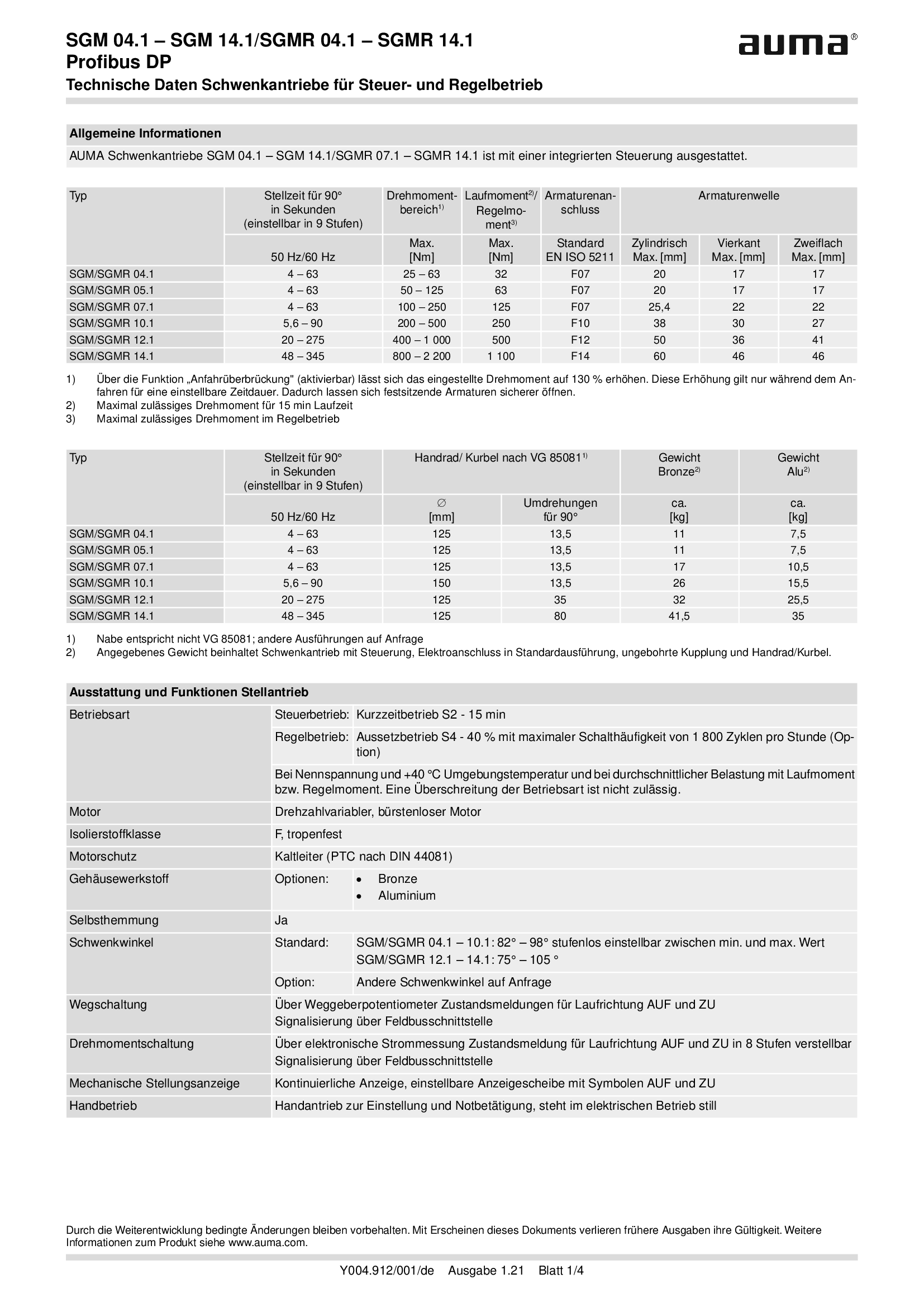
Part-turn actuators SGM/SGMR 04.1 - 14.1, Profibus DP, military ship building (navy)
Technical data
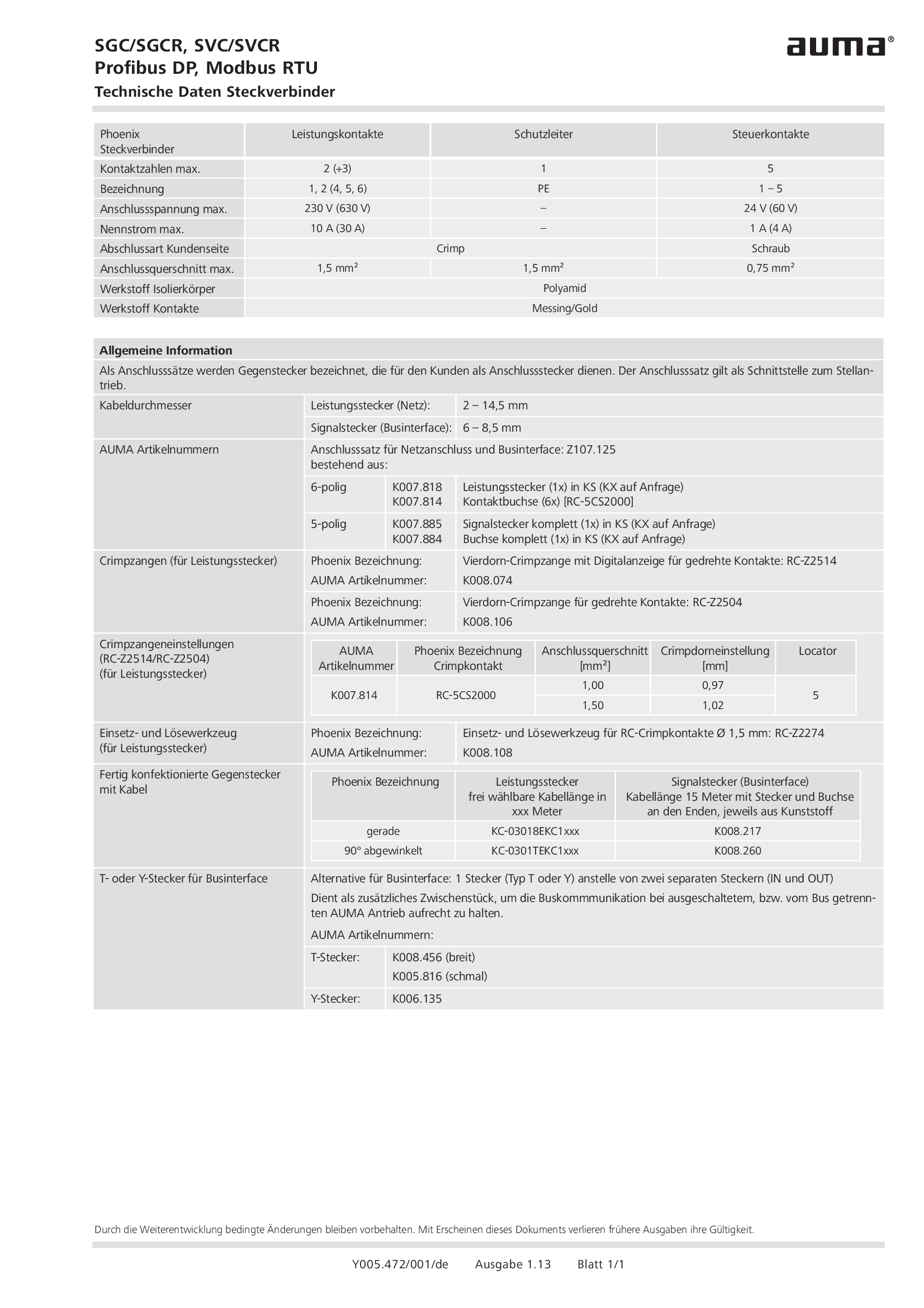
Plug/socket connector, SGC/SGCR, SVC/SVCR, Profibus DP, Modbus RTU
Technical data
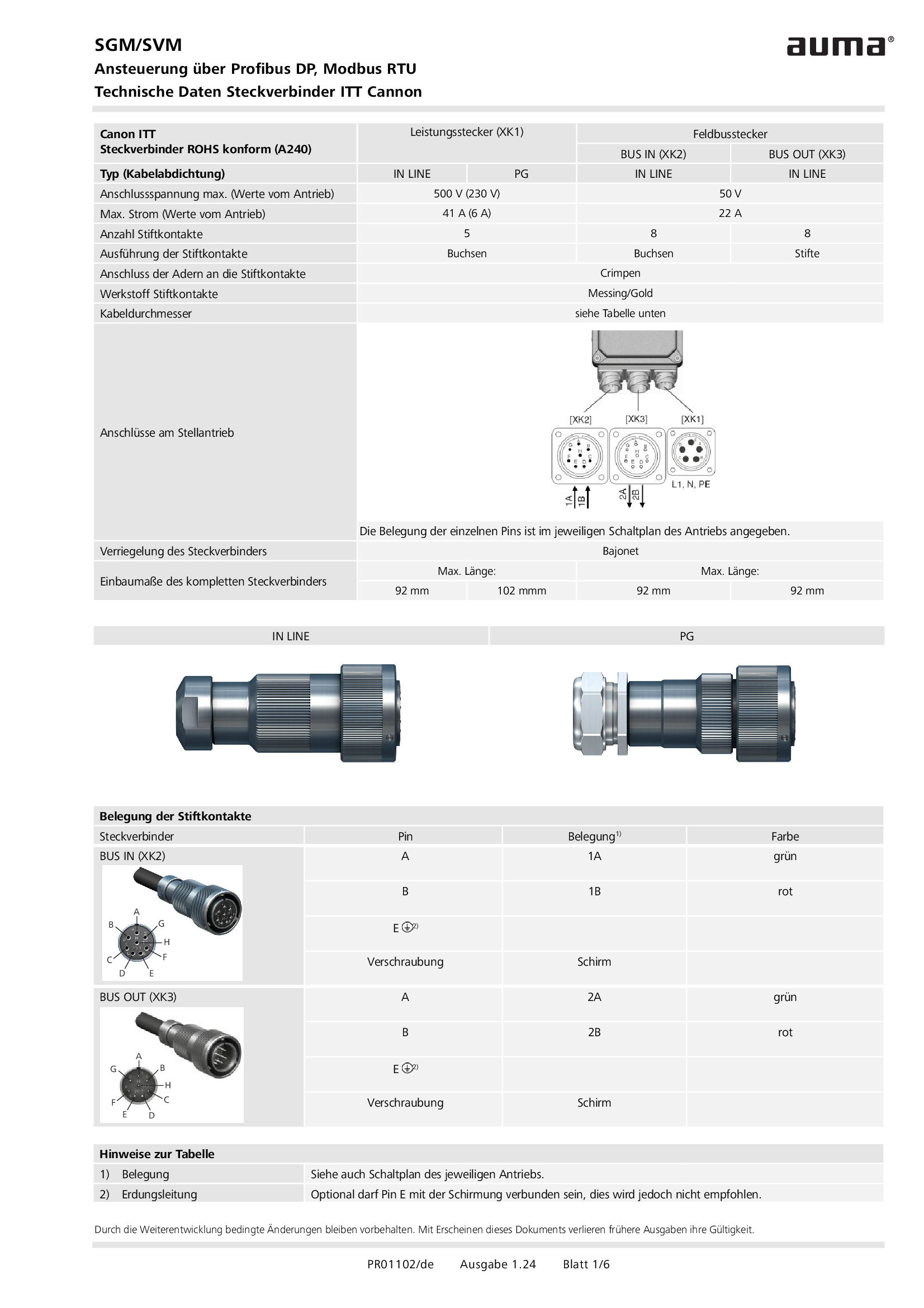
Plug/socket connector, SGM/SVM, Profibus DP, Modbus RTU, ITT Cannon
Technical data
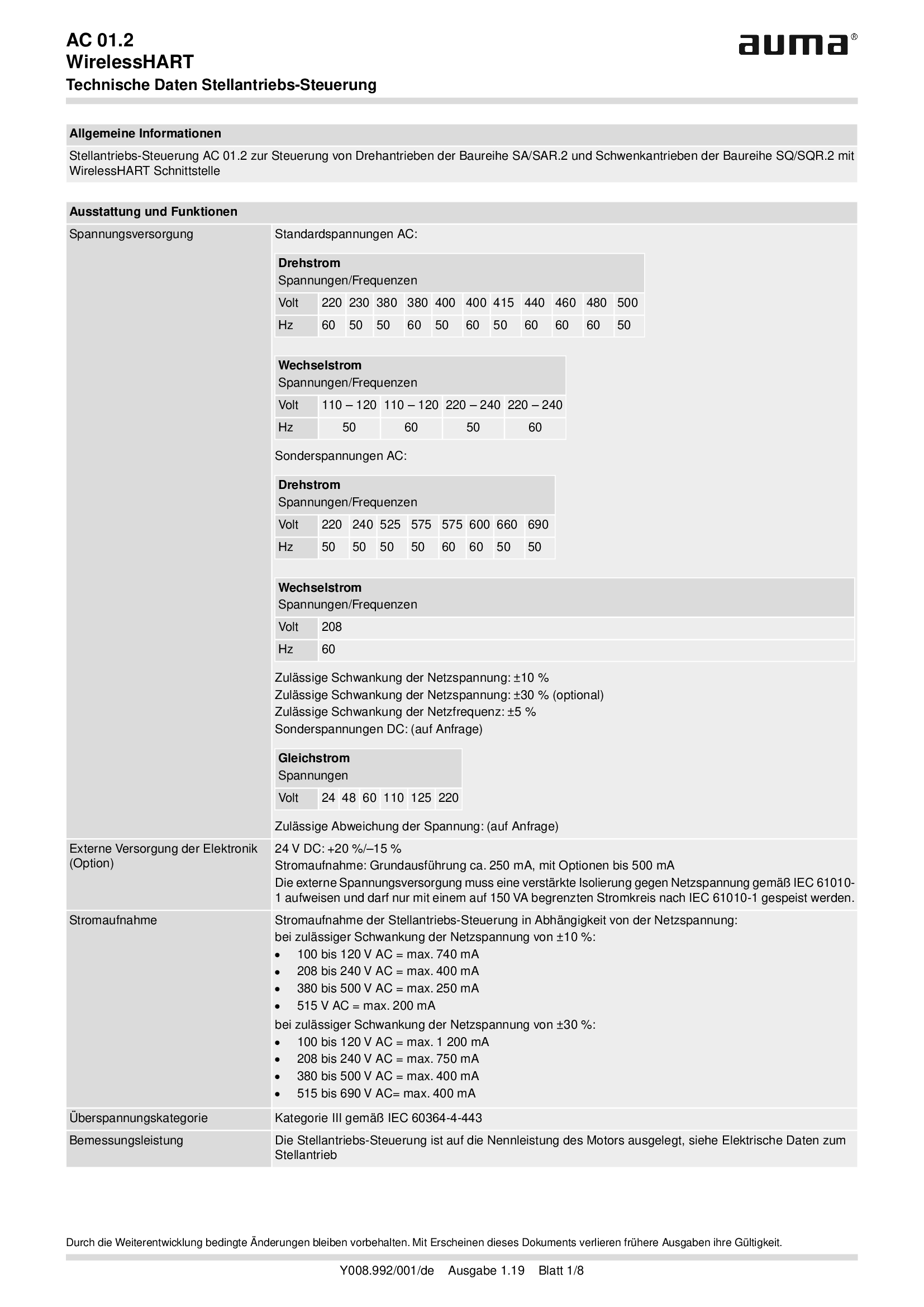
Stellantriebs-Steuerung AUMATIC AC 01.2, WirelessHART
Technical data

TIGRON, Profibus DP interface
Technical data

Valve actuators SVC/SVCR 05.1 - 07.5, Profibus DP
Technical data

Valve actuators SVM/SVMR 05.1 - 07.5, Profibus DP, military ship building (navy)
Technical data
Technical description
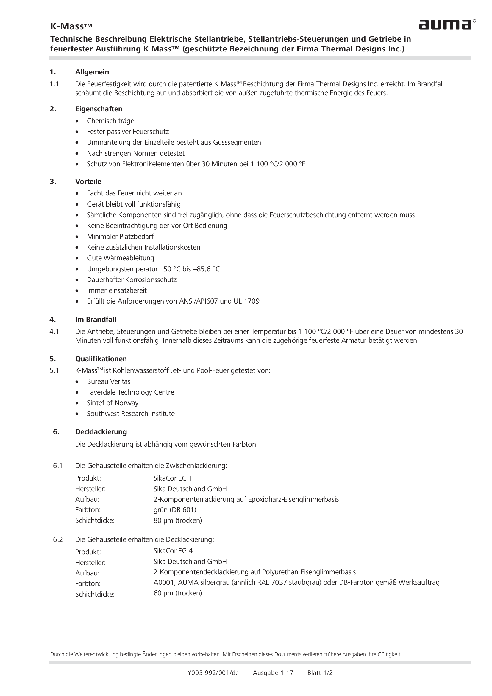
Coating for actuators, actuator controls and gearboxes in fireproof version K-Mass
Technical description
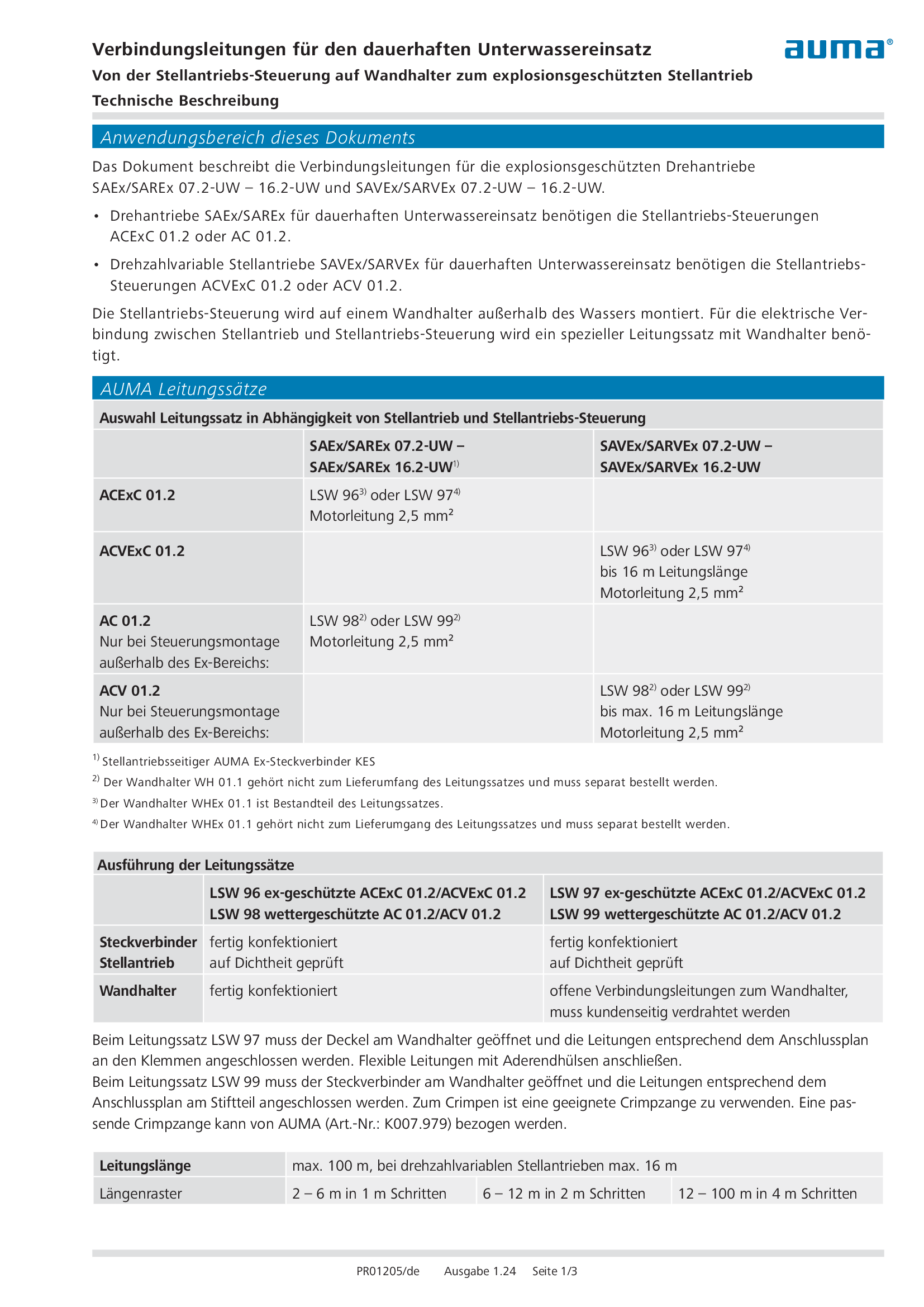
Connecting cable for continuous underwater use (explosion-proof actuator)
Technical description
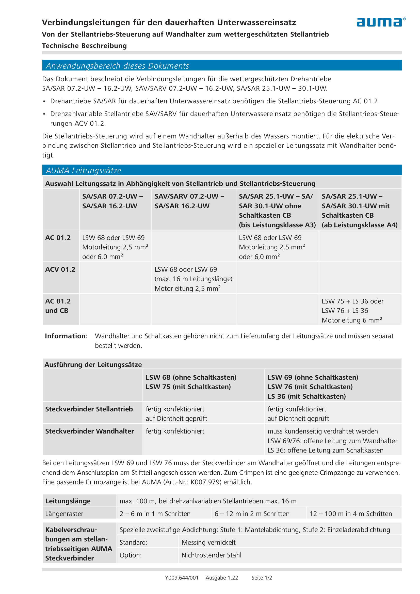
Connecting cable for continuous underwater use (weatherproof actuator)
Technical description
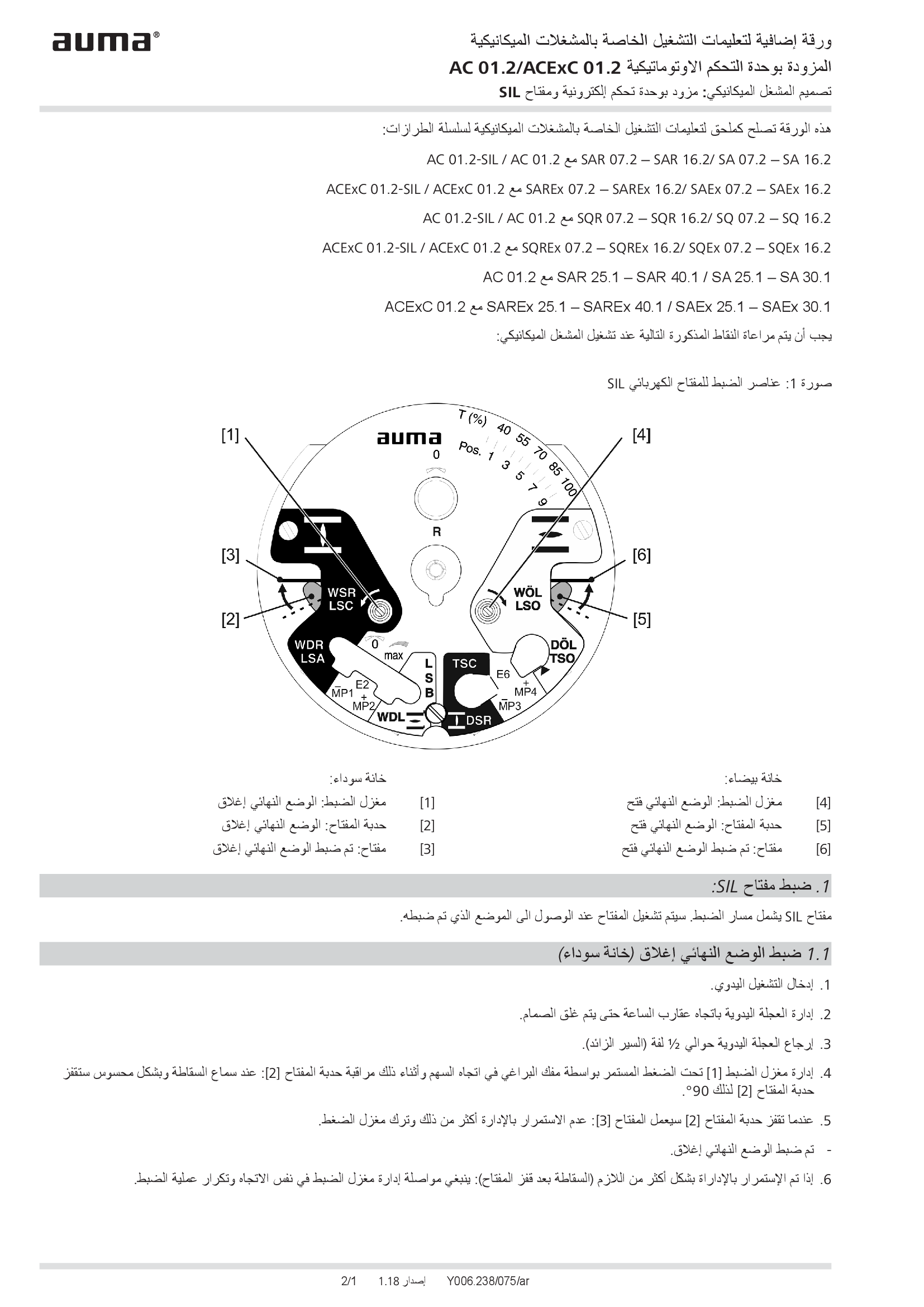
Supplement AUMATIC AC 01.2/ACExC 01.2, version actuators: with elektronic control unit (MWG) and SIL limit switching
Technical description
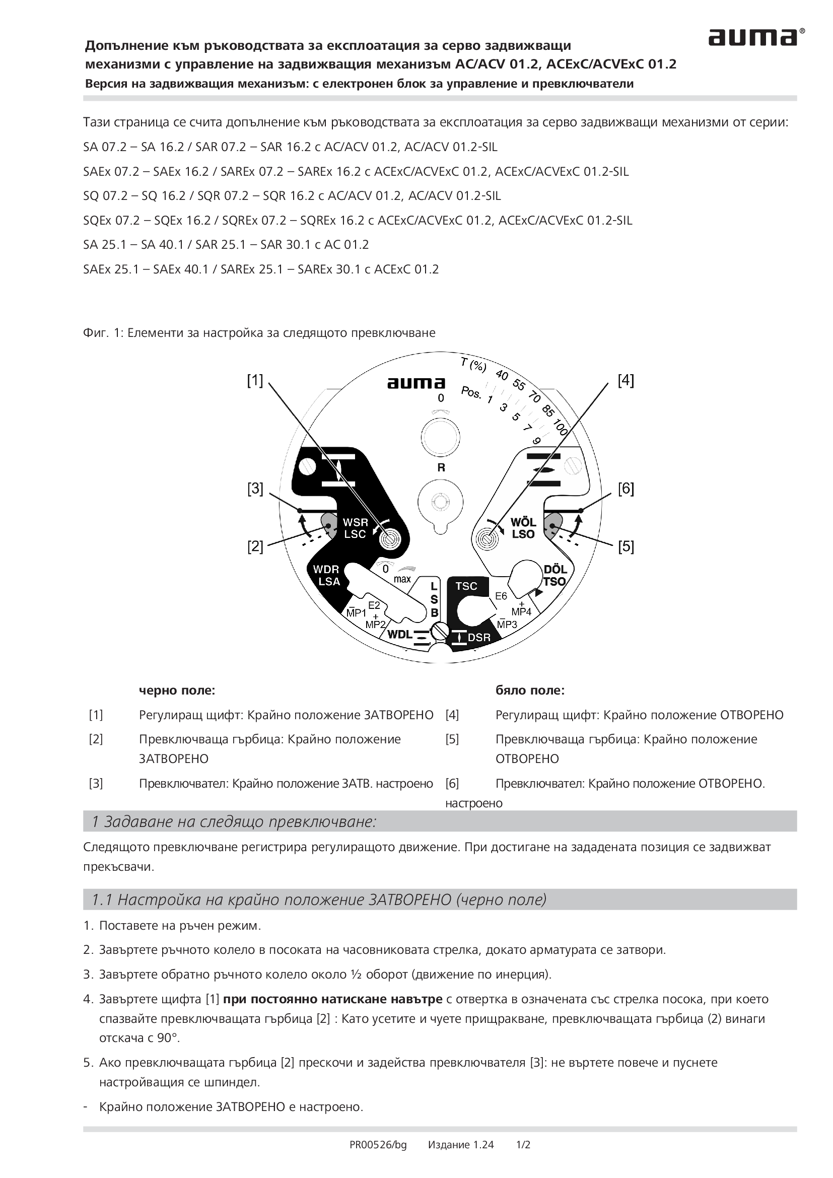
Supplement AUMATIC AC 01.2/ACExC 01.2, version actuators: with elektronic control unit (MWG) and limit switching
Technical description
Wiring diagram

A1: AUMATIC AC 01.2 position feedback signal 0/4 - 20 mA (potentiometer in actuator), basic version, reversing contactors OPEN, STOP, CLOSE, EMERGENCY (24 V DC), 6 programmable output contacts, AUMA power class A1 - A3
Wiring diagram

A1: AUMATIC ACExC 01.2 position feedback signal 0/4 - 20 mA (potentiometer in actuator),basic version, reversing contactors CLOSE, OPEN, STOP, EMERGENCY (24 V DC), 6 programmable output contacts, AUMA power class A1 - A3
Wiring diagram

A1N: AUMATIC AC 01.2 position/torque feedback signal 0/4 - 20 mA (MWG in actuator), reversing contactors OPEN, STOP, CLOSE, EMERGENCY (24 V DC), 6 programmable output contacts, AUMA power class A1 - A3
Wiring diagram

A1N: AUMATIC ACExC 01.2 position/torque feedback signal 0/4 - 20 mA (MWG in actuator), reversing contactors CLOSE, OPEN, STOP, EMERGENCY (24 V DC), 6 programmable output contacts, AUMA power class A1 - A3
Wiring diagram

A2: AUMATIC AC 01.2 positioner and postition feedback signal 0/4 - 20 mA (potentiometer in actuator), reversing contactors OPEN, STOP, CLOSE, EMERGENCY, MODE (24 V DC), 6 programmable output contacts, AUMA power class A1 - A3
Wiring diagram

A2: AUMATIC ACExC 01.2 positioner and position feedback signal 0/4 - 20 mA (potentiometer in actuator), reversing contactors MODE, CLOSE, OPEN, STOP, EMERGENCY (24 V DC), setpoint (0/4 - 20 mA), 6 programmable output contacts, AUMA power class A1 -
Wiring diagram

A2DP: AUMATIC AC 01.2 position feedback (potentiometer in actuator), basic version, reversing contactors, Profibus, AUMA power class A1 - A3
Wiring diagram

A2DP: AUMATIC ACExC 01.2 position feedback (potentiometer in actuator), basic version, reversing contactors, Profibus, AUMA power class A1 - A3
Wiring diagram

A2ENIP: AUMATIC AC 01.2 position feedback (potentiometer in actuator), basic version, reversing contactors, Ethernet/IP, AUMA power class A3 - A3
Wiring diagram

A2ENIP: AUMATIC ACExC 01.2 position feedback (potentiometer in actuator), basic version, reversing contactors, EtherNet/IP, AUMA power class A1 - A3
Wiring diagram

A2FF: AUMATIC AC 01.2 position feedback (potentiometer in actuator), basic version, Reversing contactors, Foundation Fieldbus FF, AUMA power classes A1 – A3
Wiring diagram

A2FF: AUMATIC ACExC 01.2 position feedback (potentiometer in actuator), basic version, reversing contactors, Foundation Fieldbus FF, AUMA power class A1 - A3
Wiring diagram

A2HRT: AUMATIC AC 01.2 position feedback (potentiometer in actuator), basic version, Reversing contactors, HART actuatorAUMA power classes A1 – A3
Wiring diagram

A2HRT: AUMATIC ACExC 01.2 position feedback (potentiometer in actuator), reversing contactors, HART actuator, AUMA power class A1 - A3
Wiring diagram

A2HRTCO: AUMATIC AC 01.2 position feedback (potentiometer in actuator), basic version, Reversing contactors, HART Current Output, AUMA power classes A1 – A3
Wiring diagram

A2HRTCO: AUMATIC ACExC 01.2 position feedback (potentiometer in actuator), basic version, reversing contactors, HART current output, AUMA power class A1 - A3
Wiring diagram

A2MB: AUMATIC AC 01.2 position feedback (potentiometer in actuator), basic version, reversing contactors, Modbus RTU, AUMA power class A1 - A3
Wiring diagram

A2MB: AUMATIC ACExC 01.2 position feedback (potentiometer in acuator), basic version, reversing contactors, Modbus, AUMA power class A1 - A3
Wiring diagram

A2MBTCP: AUMATIC AC 01.2 position feedback (potentiometer in actuator), basic version, Reversing contactors, Modbus TCP/IP, AUMA power classes A1 – A3
Wiring diagram

A2MBTCP: AUMATIC AC 01.2 position/torque feedback (MWG in actuator), Reversing contactors, Modbus TCP/IP, AUMA power classes A1 – A3
Wiring diagram

A2MBTCP: AUMATIC ACExC 01.2 position feedback (potentiometer in actuator), basic version, reversing contactors, Modbus TCP/IP, AUMA power class A1 - A3
Wiring diagram

A2N: AUMATIC AC 01.2 positioner and position/torque feedback signal 0/4 - 20 mA (MWG in actuator), , reversing contactors OPEN, STOP, CLOSE, EMERGENCY, MODE (24 V DC), 6 programmable output contacts, AUMA power class A1 - A3
Wiring diagram

A2N: AUMATIC ACExC 01.2 positioner and position/torque feedback signal 0/4 - 20 mA (MWG in actuator), reversing contactors MODE, CLOSE, OPEN, STOP, EMERGENCY (24 V DC), 6 programmable output contacts, AUMA power class A1 - A3
Wiring diagram

A2NDP: AUMATIC AC 01.2 position/torque feedback (MWG in actuator), reversing contactors, Profibus, AUMA power class A1 - A3
Wiring diagram

A2NDP: AUMATIC ACExC 01.2 position/torque feedback (MWG in actuator), reversing contactors, Profibus, AUMA power class A1 - A3
Wiring diagram

A2NENIP: AUMATIC AC 01.2, position/torque feedback (MWG in actuator, reversing contactors, Ethernet/IP, AUMA power class A1 - A 3
Wiring diagram

A2NENIP: AUMATIC ACExC 01.2 position/torque feedback (MWG in actuator), reversing contactors, EtherNet/IP, AUMA power class A1 - A3
Wiring diagram

A2NFF: AUMATIC AC 01.2 position/torque feedback (MWG in actuator), Reversing contactors, Foundation Fieldbus FF, AUMA power classes A1 – A3
Wiring diagram

A2NFF: AUMATIC ACExC 01.2 Stellungs-/Drehmomentrückmeldung (MWG im Stellanrieb), Schütze, Foundation Fieldbus FF, AUMA Leisungsklasse A1 - A3
Wiring diagram

A2NFF: AUMATIC ACExC 01.2 position/torque feedback (MWG in actuator), reversing contactors, Foundation Fieldbus FF, AUMA power class A1 - A3
Wiring diagram

A2NHRT: AUMATIC AC 01.2 position/torque feedback (MWG in actuator), Reversing contactors, HART actuator, AUMA power classes A1 – A3
Wiring diagram

A2NHRT: AUMATIC ACExC 01.2 position/torque feedback (MWG in actuator), reversing contactors, HART actuator, AUMA power class A1 - A3
Wiring diagram

A2NHRTCO: AUMATIC AC 01.2 position/torque feedback (MWG in actuator), Reversing contactors, HART Current Output, AUMA power classes A1 – A3
Wiring diagram

A2NHRTCO:AUMATIC ACExC 01.2 position/torque feedback (MWG in actuator), reversing contactors, HART current output, AUMA power class A1 - A3
Wiring diagram

A2NMB: AUMATIC AC 01.2 position/torque feedback (MWG in actuator), reversing contactors, Modbus RTU, AUMA power class A1 - A3
Wiring diagram

A2NMB: AUMATIC ACExC 01.2 position/torque feedback (MWG in actuator), reversing contactors, Modbus, AUMA power class A1 - A3
Wiring diagram

A2NMBTCP: AUMATIC ACExC 01.2 position/torque feedback (MWG in actuator), reversing contactors, Modbus TCP/IP, AUMA power class A1 - A3
Wiring diagram

A3: AUMATIC AC 01.2 positioner and position feedback signal 0/4 - 20 mA (potentiometer in actuator), thyristors OPEN, STOP, CLOSE, EMERGENCY, MODE (24 V DC), 6 programmable output contacts, AUMA power class B1/B2
Wiring diagram

A3: AUMATIC AC 01.2 positioner and position feedback signal 0/4 - 20 mA (potentiometer in actuator), thyristors OPEN, STOP, CLOSE, EMERGENCY, MODE (24 V DC), 6 programmable output contacts, AUMA power class B3
Wiring diagram

A3: AUMATIC ACExC 01.2 positioner and position feedback signal 0/4 - 20 mA (potentiometer in actuator), thyristors MODE, CLOSE, OPEN, STOP, EMERGENCY (24 V DC), setpoint (0/4 - 20 mA) 6 programmable output contacts, AUMA power class B1/B2
Wiring diagram

A3: AUMATIC ACExC 01.2 positioner and position feedback signal 0/4 - 20 mA (potentiometer in actuator), thyristors MODE, CLOSE, OPEN, STOP, EMERGENCY (24 V DC), setpoint (0/4 - 20 mA) 6 programmable output contacts, AUMA power class B3
Wiring diagram

A3DP: AUMATIC AC 01.2 position feedback (potentiometer in actuator), thyristors, Profibus, AUMA power class B1/B2
Wiring diagram

A3DP: AUMATIC AC 01.2 position feedback (potentiometer in actuator), thyristors, Profibus, AUMA power class B2
Wiring diagram

A3DP: AUMATIC ACExC 01.2 position feedback (potentiometer in actuator), thyristors, Profibus, AUMA power class B1/B2
Wiring diagram

A3DP: AUMATIC ACExC 01.2 position feedback (potentiometer in actuator), thyristors, Profibus, AUMA power class B3
Wiring diagram

A3ENIP: AUATIC AC 01.2 postition feedback (potentiometer in actuator), Thyristors, EtherNet/IP, AUMA power class B1/B2
Wiring diagram

A3ENIP: AUATIC AC 01.2 postition feedback (potentiometer in actuator), Thyristors, EtherNet/IP, AUMA power class B3
Wiring diagram

A3ENIP: AUATIC ACExC 01.2 position feedback (potentiometer in actuator), Thyristors, EtherNet/IP, AUMA power class B1/B2
Wiring diagram

A3ENIP: AUATIC ACExC 01.2 position feedback (potentiometer in actuator), Thyristors, EtherNet/IP, AUMA power class B3
Wiring diagram

A3FF: AUMATIC AC 01.2 position feedback (potentiometer in actuator), Thyristors, Foundation Fieldbus FF, AUMA power class B1/B2
Wiring diagram

A3FF: AUMATIC AC 01.2 position feedback (potentiometer in actuator), Thyristors, Foundation Fieldbus FF, AUMA power class B3
Wiring diagram

A3FF: AUMATIC ACExC 01.2 position feedback (potentiometer in actuator), Thyristors, Foundation Fieldbus FF, AUMA power class B1/B2
Wiring diagram

A3FF: AUMATIC ACExC 01.2 position feedback (potentiometer in actuator), Thyristors, Foundation Fieldbus FF, AUMA power class B3
Wiring diagram

A3HRT: AUMATIC AC 01.2 position feedback (potentiometer in actuator), Thyristors, HART actuator, AUMA power class B1/B2
Wiring diagram

A3HRT: AUMATIC AC 01.2 position feedback (potentiometer in actuator), Thyristors, HART actuator, AUMA power class B3
Wiring diagram

A3HRT: AUMATIC ACExC 01.2 position feedback (potentiometer in actuator) Thyristors, HART actuator, AUMA power class B1/B2
Wiring diagram

A3HRT: AUMATIC ACExC 01.2 position feedback (potentiometer in actuator) Thyristors, HART actuator, AUMA power class B3
Wiring diagram

A3HRTCO: AUMATIC AC 01.2 position feedback (potentiometer in actuator), Thyristors, HART Current Output, AUMA power class B1/B2
Wiring diagram

A3HRTCO: AUMATIC AC 01.2 position feedback (potentiometer in actuator), Thyristors, HART Current Output, AUMA power class B3
Wiring diagram

A3HRTCO: AUMATIC ACExC 01.2 position feedback (potentiometer in actuator), Thyristors, HART current output, AUMA power class B1/B2
Wiring diagram

A3HRTCO: AUMATIC ACExC 01.2 position feedback (potentiometer in actuator), Thyristors, HART current output, AUMA power class B3
Wiring diagram

A3MB: AUMATIC AC 01.2 position feedback (potentiometer in actuator), thyristors, Modbus, AUMA power class B1/B2
Wiring diagram

A3MB: AUMATIC AC 01.2 position feedback (potentiometer in actuator), thyristors, Modbus, AUMA power class B3
Wiring diagram

A3MB: AUMATIC ACExC 01.2 position feedback (potentiometer in actuator), thyristors, Modbus, AUMA power class B1/B2
Wiring diagram

A3MB: AUMATIC ACExC 01.2 position feedback (potentiometer in actuator), thyristors, Modbus, AUMA power class B3
Wiring diagram

A3MBTCP: AUMATIC AC 01.2 position feedback (potentiometer in actuator), Thyristors, Modbus TCP/IP, AUMA power class B1/B2
Wiring diagram

A3MBTCP: AUMATIC AC 01.2 position feedback (potentiometer in actuator), Thyristors, Modbus TCP/IP, AUMA power class B3
Wiring diagram

A3MBTCP: AUMATIC ACExC 01.2 position feedback (potentiometer in actuator), Thyristors, Modbus TCP/IP, AUMA power class B1/B2
Wiring diagram

A3MBTCP: AUMATIC ACExC 01.2 position feedback (potentiometer in actuator), Thyristors, Modbus TCP/IP, AUMA power class B3
Wiring diagram

A3N: AUMATIC AC 01.2 positioner and position/torque feedback signal 0/4 - 20 mA (MWG in actuator), thyristors OPEN, STOP, CLOSE, EMERGENCY, MODE (24 V DC), 6 programmable output contacts, AUMA power class B1/B2
Wiring diagram

A3N: AUMATIC AC 01.2 positioner and position/torque feedback signal 0/4 - 20 mA (MWG in actuator), thyristors OPEN, STOP, CLOSE, EMERGENCY, MODE (24 V DC), 6 programmable output contacts, AUMA power class B3
Wiring diagram

A3N: AUMATIC ACExC 01.2 positioner and position/torque feedback signal 0/4 - 20 mA (MWG in actuator), thyristors MODE, CLOSE, OPEN, STOP, EMERGENCY (24 V DC), setpoint (0/4 - 20 mA), 6 programmable output contacts, AUMA power class B1/B2
Wiring diagram

A3N: AUMATIC ACExC 01.2 positioner and position/torque feedback signal 0/4 - 20 mA (MWG in actuator), thyristors MODE, CLOSE, OPEN, STOP, EMERGENCY (24 V DC), setpoint (0/4 - 20 mA), 6 programmable output contacts, AUMA power class B3
Wiring diagram

A3NDP: AUMATIC AC 01.2 position/torque feedback (MWG in actuator), thyristors, Profibus, AUMA power class B1/B2
Wiring diagram

A3NDP: AUMATIC AC 01.2 position/torque feedback (MWG in actuator), thyristors, Profibus, AUMA power class B3
Wiring diagram

A3NDP: AUMATIC ACExC 01.2 position/torque feedback (MWG in actuator), thyristors, Profibus, AUMA power class B1/B2
Wiring diagram

A3NDP: AUMATIC ACExC 01.2 position/torque feedback (MWG in actuator), thyristors, Profibus, AUMA power class B3
Wiring diagram

A3NENIP: AUMATIC AC 01.2 position/torque feedback (MWG in actuator), Thyristors, Ethernet/IP, AUMA power class B1/B2
Wiring diagram

A3NENIP: AUMATIC AC 01.2 position/torque feedback (MWG in actuator), Thyristors, Ethernet/IP, AUMA power class B3
Wiring diagram

A3NENIP: AUMATIC ACExC 01.2 position/torque feedback (MWG in actuator), Thyristors, EtherNet/IP, AUMA power class B1/B2
Wiring diagram

A3NENIP: AUMATIC ACExC 01.2 position/torque feedback (MWG in actuator), Thyristors, EtherNet/IP, AUMA power class B3
Wiring diagram

A3NFF: AUMATIC AC 01.2 position/torque feedback (MWG in actuator), Thyristors, Foundation Fieldbus FF, AUMA power class B1/B2
Wiring diagram

A3NFF: AUMATIC AC 01.2 position/torque feedback (MWG in actuator), Thyristors, Foundation Fieldbus FF, AUMA power class B3
Wiring diagram

A3NFF: AUMATIC ACExC 01.2 position/torque feedback (MWG in actuator), Thyristors, Foundation Fieldbus FF, AUMA power class B1/B2
Wiring diagram

A3NFF: AUMATIC ACExC 01.2 position/torque feedback (MWG in actuator), Thyristors, Foundation Fieldbus FF, AUMA power class B3
Wiring diagram

A3NHRT: AUMATIC AC 01.2 position/torque feedback (MWG in actuator), Thyristors, HART actuator, AUMA power class B1/B2
Wiring diagram

A3NHRT: AUMATIC AC 01.2 position/torque feedback (MWG in actuator), Thyristors, HART actuator, AUMA power class B3
Wiring diagram

A3NHRT: AUMATIC ACExC 01.2 position/torque feedback (MWG in actuator), Thyristors, HART actuator, AUMA power class B1/B2
Wiring diagram

A3NHRT: AUMATIC ACExC 01.2 position/torque feedback (MWG in actuator), Thyristors, HART actuator, AUMA power class B3
Wiring diagram

A3NHRTCO: AUMATIC AC 01.2 position/torque feedback (MWG in actuator), Thyristors, HART actuator, AUMA power class B1/B2
Wiring diagram

A3NHRTCO: AUMATIC AC 01.2 position/torque feedback (MWG in actuator), Thyristors, HART actuator, AUMA power class B3
Wiring diagram

A3NHRTCO: AUMATIC ACExC 01.2 position/torque feedback (MWG in actuator), Thyristors, HART current output, AUMA power class B1/B2
Wiring diagram

A3NHRTCO: AUMATIC ACExC 01.2 position/torque feedback (MWG in actuator), Thyristors, HART current output, AUMA power class B3
Wiring diagram

A3NMB: AUMATIC AC 01.2 position/torque feedback (MWG in actuator), thyristors, Modbus RTU, AUMA power class B1/B2
Wiring diagram

A3NMB: AUMATIC AC 01.2 position/torque feedback (MWG in actuator), thyristors, Modbus RTU, AUMA power class B3
Wiring diagram

A3NMB: AUMATIC ACExC 01.2 position/torque feedback (MWG in actuator), thyristors, Modbus, AUMA power class B1/B2
Wiring diagram


