Wiring diagram

AV2HRTCO: AUMATIC ACV 01.2 position feedback (potentiometer in actuator), basic version, HART Current Output, 1-ph; 220 V - 240 V
Wiring diagram

AV2HRTCO: AUMATIC ACV 01.2 position feedback (potentiometer in actuator), basic version, HART Current Output, 3-ph; 380 V- 480 V
Wiring diagram

AV2HRTCO: AUMATIC ACVExC 01.2 position feedback (potentiometer in actuator), basic version, HART Current Output, 1-ph; 220 V - 240 V
Wiring diagram

AV2HRTCO: AUMATIC ACVExC 01.2 position feedback (potentiometer in actuator), basic version, HART Current Output, 3-ph; 38 V - 480 V
Wiring diagram

AV2HRTCO: AUMATIC ACVExC 01.2 position feedback (potentiometer in actuator), basic version, HART Current Output, 3-ph; 380 V - 480 V
Wiring diagram

AV2MB: AUMATIC ACV 01.2 position feedback signal (potentiometer in actuator), basic version, Modbus, 1-ph; 220 V- 240 V
Wiring diagram

AV2MB: AUMATIC ACV 01.2 position feedback signal (potentiometer in actuator), basic version, Modbus, 3-ph; 380 V - 480 V
Wiring diagram

AV2MB: AUMATIC ACVExC 01.2 position feedback (potentiometer in actuator), basic version, Modbus RTU, 1-ph; 220 V - 240 V
Wiring diagram

AV2MB: AUMATIC ACVExC 01.2 position feedback (potentiometer in actuator), basic version, Modbus RTU, 3ph; 220 V - 240 V
Wiring diagram

AV2MB: AUMATIC ACVExC 01.2 position feedback (potentiometer in actuator), basic version, Modbus RTU, 3ph; 380 V - 480 V
Wiring diagram

AV2MBTCP: AUMATIC ACV 01.2 position feedback (potentiometer in actuator), basic version, Modbus TCP/IP, 1-ph; 220 V - 240 V
Wiring diagram

AV2MBTCP: AUMATIC ACV 01.2 position feedback (potentiometer in actuator), basic version, Modbus TCP/IP, 3-ph; 380 V - 480 V
Wiring diagram

AV2MBTCP: AUMATIC ACVExC 01.2 position feedback (ptentiometer in actuator), basic version Modbus TCP/IP, 1-ph; 220 V - 240 V
Wiring diagram

AV2MBTCP: AUMATIC ACVExC 01.2 position feedback (ptentiometer in actuator), basic version Modbus TCP/IP, 3-ph; 380 V - 480 V
Wiring diagram

AV2N: AUMATIC ACVExC 01.2 positioner and position/torque feedback signal 0/4 - 20 mA (MWG in actuator), MODE, CLOSE, OPEN, STOP, EMERGENCY (24 V DC), setpoint (0/4 - 20 mA), 6 programmable output contacts, 1-ph 220 V - 240 V
Wiring diagram

AV2N: AUMATIC ACVExC 01.2 positioner and position/torque feedback signal 0/4 - 20 mA (MWG in actuator), MODE, CLOSE, OPEN, STOP, EMERGENCY (24 V DC), setpoint (0/4 - 20 mA), 6 programmable output contacts, 3-ph 380 V - 480 V
Wiring diagram

AV2NDP: AUMATIC ACV 01.2 position/torque feedback (MWG in actuator), Profibus, 1-ph; 220 V - 240 V
Wiring diagram

AV2NDP: AUMATIC ACV 01.2 position/torque feedback (MWG in actuator), Profibus, 3-ph; 380 V - 480 V
Wiring diagram

AV2NDP: AUMATIC ACVExC 01.2 position/torque feedback (MWG in actuator), Profibus, 1-ph; 220 V - 240 V
Wiring diagram

AV2NDP: AUMATIC ACVExC 01.2 position/torque feedback (MWG in actuator), Profibus, 3-ph; 380 V - 480 V
Wiring diagram

AV2NFF: AUMATIC ACV 01.2 position feedback/torque signal (potentiometer in actuator), Foundation Fieldbus FF, 1 ph; 220 V - 240 V
Wiring diagram

AV2NFF: AUMATIC ACV 01.2 position feedback/torque signal (potentiometer in actuator), Foundation Fieldbus FF, 3 ph; 380 V - 480 V
Wiring diagram

AV2NFF: AUMATIC ACVExC 01.2 position/torque feedback (MWG in actuator), Foundation Fieldbus FF, 1-ph; 220 V - 480 V
Wiring diagram

AV2NFF: AUMATIC ACVExC 01.2 position/torque feedback (MWG in actuator), Foundation Fieldbus FF, 3-ph; 380 V - 480 V
Wiring diagram

AV2NHRT: AUMATIC AC 01.2 position/torque feedback (MWG in actuator), HART actuator, 3-ph; 380 V - 480 V
Wiring diagram

AV2NHRT: AUMATIC ACV 01.2 position/torque feedback (MWG in actuator), HART actuator, 1-ph; 220 V - 240 V
Wiring diagram

AV2NHRT: AUMATIC ACVExC 01.2 position/torque feedback (MWG in actuator), HART, 1-ph; 220 V - 240 V
Wiring diagram

AV2NHRT: AUMATIC ACVExC 01.2 position/torque feedback (MWG in actuator), HART, 3-ph; 380 V - 480 V
Wiring diagram

AV2NHRTCO: AUMATIC ACV 01.2 position/torque feedback (MWG in actuator), HART Current Output, 1-ph; 220 V - 240 V
Wiring diagram

AV2NHRTCO: AUMATIC ACV 01.2 position/torque feedback (MWG in actuator), HART Current Output, 3-ph; 380 V - 480 V
Wiring diagram

AV2NHRTCO: AUMATIC ACVExC 01.2 position/torque feedback (MWG in actuator), HART Current Output, 1-ph; 220 V - 240 V
Wiring diagram

AV2NHRTCO: AUMATIC ACVExC 01.2 position/torque feedback (MWG in actuator), HART Current Output, 3-ph; 380 V - 480 V
Wiring diagram

AV2NMB: AUMATIC ACV 01.2 position/torque feedback (MWG in actuator), Modbus, 1-ph; 220 V- 240 V
Wiring diagram

AV2NMB: AUMATIC ACV 01.2 position/torque feedback (MWG in actuator), Modbus, 3-ph; 380 V - 480 V
Wiring diagram

AV2NMB: AUMATIC ACVExC 01.2 position/torque feedback (MWG in actuator), Modbus RTU, 1-ph; 220 V - 240 V
Wiring diagram

AV2NMB: AUMATIC ACVExC 01.2 position/torque feedback (MWG in actuator), Modbus RTU, 3-ph; 380 V - 480 V
Wiring diagram

AV2NMBTCP: AUMATIC ACV 01.2 position/torque feedback (MWG in actuator), Modbus TCP/IP, 1-ph; 220 V - 240 V
Wiring diagram

AV2NMBTCP: AUMATIC ACV 01.2 position/torque feedback (MWG in actuator), Modbus TCP/IP, 3-ph; 380 V - 480 V
Wiring diagram

AV2NMBTCP: AUMATIC ACVExC 01.2 position/torque feedback (MWG in actuator), Modbus TCP/IP, 1-ph; 220 V - 240 V
Wiring diagram

AV2NMBTCP: AUMATIC ACVExC 01.2 position/torque feedback (MWG in actuator), Modbus TCP/IP, 3-ph; 380 V - 480 V
Wiring diagram

AV2NPN: AUMATIC ACV 01.2 position/torque feedback (MWG in actuator), Profinet, 1-ph; 220 V - 240 V
Wiring diagram

AV2NPN: AUMATIC ACV 01.2 position/torque feedback (MWG in actuator), Profinet, 3-ph; 380 V - 480 V
Wiring diagram

AV2PN: AUMATIC ACV 01.2 position feedback (potentiometer in actuator), Profinet, 1-ph; 220 V - 240 V
Wiring diagram

AV2PN: AUMATIC ACV 01.2 position feedback (potentiometer in actuator), Profinet, 3-ph; 380 V - 480 V
Wiring diagram

AV4DP: AUMATIC ACV 01.2 positioner and position feedback signal 0/4 – 20 mA (potentiometer in actuator), basic version, MODE, CLOSE, OPEN, STOP, EMERGENCY, I/O (24 V DC), 6 programmable output contacts, Profibus, 1-ph; 220 V - 240 V
Wiring diagram

AV4DP: AUMATIC ACV 01.2 positioner and position feedback signal 0/4 – 20 mA (potentiometer in actuator), basic version, MODE, CLOSE, OPEN, STOP, EMERGENCY, I/O (24 V DC), 6 programmable output contacts, Profibus, 3-ph; 380 V - 480 V
Wiring diagram

AV4DP: AUMATIC ACVExC 01.2 positioner und position feedback signal 0/4 - 20 mA (potentiometer in actuator), basic version, MODE, CLOSE, OPEN, STOP, EMERGENCY, I/O ( 24 V DC), 6 programmable output contacts, Profibus DP, 1-ph; 220 V - 240 V
Wiring diagram

AV4DP: AUMATIC ACVExC 01.2 positioner und position feedback signal 0/4 - 20 mA (potentiometer in actuator), basic version, MODE, CLOSE, OPEN, STOP, EMERGENCY, I/O ( 24 V DC), 6 programmable output contacts, Profibus DP, 3-ph; 380 V - 480 V
Wiring diagram

AV4FF: AUMATIC ACExC 01.2 positioner and position feedback signal 0/4 - 20 mA (potentiometer in actuator), basic version, MODE, CLOSE, OPEN, STOP, EMERGENCY, I/O ( 24 V DC), 6 programmable output contacts, Foundation Fieldbus FF, 1-ph; 220 V - 240 V
Wiring diagram

AV4FF: AUMATIC ACExC 01.2 positioner and position feedback signal 0/4 - 20 mA (potentiometer in actuator), basic version, MODE, CLOSE, OPEN, STOP, EMERGENCY, I/O ( 24 V DC), 6 programmable output contacts, Foundation Fieldbus FF, 3-ph; 380 V - 480 V
Wiring diagram

AV4FF: AUMATIC ACV 01.2 positioner and position feedback signal 0/4 – 20 mA (potentiometer in actuator), basic version, MODE, CLOSE, OPEN, STOP, EMERGENCY, I/O (24 V DC), 6 programmable output contacts, Foundation Fieldbus, 1-ph; 220 V - 240 V
Wiring diagram

AV4FF: AUMATIC ACV 01.2 positioner and position feedback signal 0/4 – 20 mA (potentiometer in actuator), basic version, MODE, CLOSE, OPEN, STOP, EMERGENCY, I/O (24 V DC), 6 programmable output contacts, Foundation Fieldbus, 3-ph; 380 V - 480 V
Wiring diagram

AV4HRT: AUMATIC ACV 01.2 positioner and position feedback signal 0/4 – 20 mA (potentiometer in actuator), basic version, MODE, CLOSE, OPEN, STOP, EMERGENCY, I/O (24 V DC), 6 programmable output contacts, HART, 1-ph; 220 V - 240 V
Wiring diagram

AV4HRT: AUMATIC ACV 01.2 positioner and position feedback signal 0/4 – 20 mA (potentiometer in actuator), basic version, MODE, CLOSE, OPEN, STOP, EMERGENCY, I/O (24 V DC), 6 programmable output contacts, HART, 3-ph; 380 V - 480 V
Wiring diagram

AV4HRT: AUMATIC ACVExC 01.2 positioner and position feedback signal 0/4 - 20 mA (potentiometer in actuator), basic version, MODE, CLOSE, OPEN, STOP, EMERGENCY; I/O (24 V DC), 6 programmable output contacts, HART, 1-ph; 220 V - 240 V
Wiring diagram

AV4HRT: AUMATIC ACVExC 01.2 positioner and position feedback signal 0/4 - 20 mA (potentiometer in actuator), basic version, MODE, CLOSE, OPEN, STOP, EMERGENCY; I/O (24 V DC), 6 programmable output contacts, HART, 3-ph; 380 V - 480 V
Wiring diagram

AV4HRTCO: AUMATIC ACV 01.2 positioner and position feedback signal 0/4 – 20 mA (potentiometer in actuator), basic version, MODE, CLOSE, OPEN, STOP, EMERGENCY, I/O (24 V DC), 6 programmable output contacts, HART, 1-ph; 220 V - 240 V
Wiring diagram

AV4HRTCO: AUMATIC ACV 01.2 positioner and position feedback signal 0/4 – 20 mA (potentiometer in actuator), basic version, MODE, CLOSE, OPEN, STOP, EMERGENCY, I/O (24 V DC), 6 programmable output contacts, HART, 3-ph; 380 V - 480 V
Wiring diagram

AV4HRTCO: AUMATIC ACVExC 01.2 positioner and position feedback signal 0/4 - 20 mA (potentiometer in actuator), basic version, MODE, CLOSE, OPEN, STOP, EMERGENCY, I/O (24 V DC), 6 programmable output contacts, HART Current output, 1-ph; 220 V - 240 V
Wiring diagram

AV4HRTCO: AUMATIC ACVExC 01.2 positioner and position feedback signal 0/4 - 20 mA (potentiometer in actuator), basic version, MODE, CLOSE, OPEN, STOP, EMERGENCY, I/O (24 V DC), 6 programmable output contacts, HART Current output, 3-ph; 380 V - 480 V
Wiring diagram

AV4MB: AUMATIC ACV 01.2 positioner and position feedback signal 0/4 – 20 mA (potentiometer in actuator), basic version, MODE, CLOSE, OPEN, STOP, EMERGENCY, I/O (24 V DC), 6 programmable output contacts, Modbus, 1-ph; 220 V - 240 V
Wiring diagram

AV4MB: AUMATIC ACV 01.2 positioner and position feedback signal 0/4 – 20 mA (potentiometer in actuator), basic version, MODE, CLOSE, OPEN, STOP, EMERGENCY, I/O (24 V DC), 6 programmable output contacts, Modbus, 3-ph; 380 V - 480 V
Wiring diagram

AV4MB: AUMATIC ACVExC 01.2 positionier and position feedback signal 0/4 - 20 mA (potentiometer in actuator), basic version, MODE, CLOSE, OPEN, STOP, EMERGENCY, I/O (24 V DC), 6 programmable output contacts, Modbus RTU, 1-ph; 220 V - 240 V
Wiring diagram

AV4MB: AUMATIC ACVExC 01.2 positionier and position feedback signal 0/4 - 20 mA (potentiometer in actuator), basic version, MODE, CLOSE, OPEN, STOP, EMERGENCY, I/O (24 V DC), 6 programmable output contacts, Modbus RTU, 3-ph; 380 V - 480 V
Wiring diagram

AV4MBTCP: AUMATIC ACV 01.2 positioner and position feedback signal 0/4 – 20 mA (potentiometer in actuator), basic version, MODE, CLOSE, OPEN, STOP, EMERGENCY, I/O (24 V DC), 6 programmable output contacts, Modbus TCP/IP, 1-ph; 220 V - 240 V
Wiring diagram

AV4MBTCP: AUMATIC ACV 01.2 positioner and position feedback signal 0/4 – 20 mA (potentiometer in actuator), basic version, MODE, CLOSE, OPEN, STOP, EMERGENCY, I/O (24 V DC), 6 programmable output contacts, Modbus TCP/IP, 3-ph; 380 V - 480 V
Wiring diagram

AV4MBTCP: AUMATIC ACVExC 01.2 positioner and position feedbak signal 0/4 - 20 mA (potentiometer in actuator), basic version, MODE, CLOSE, OPEN, STOP, EMERGENCY, I/O (24 V DC), 6 programmable output contacts, Modbus TCP/IP 1-ph; 220 V - 240 V
Wiring diagram

AV4MBTCP: AUMATIC ACVExC 01.2 positioner and position feedbak signal 0/4 - 20 mA (potentiometer in actuator), basic version, MODE, CLOSE, OPEN, STOP, EMERGENCY, I/O (24 V DC), 6 programmable output contacts, Modbus TCP/IP 3-ph; 380 V - 480 V
Wiring diagram

AV4NDP: AUMATIC ACV 01.2 positioner and position/torque feedback signal 0/4 – 20 mA (MWG in actuator), MODE, CLOSE, OPEN, STOP, EMERGENCY, I/O (24 V DC), 6 programmable output contacts, Profibus DP, 1-ph; 220 V - 240 V
Wiring diagram

AV4NDP: AUMATIC ACV 01.2 positioner and position/torque feedback signal 0/4 – 20 mA (MWG in actuator), MODE, CLOSE, OPEN, STOP, EMERGENCY, I/O (24 V DC), 6 programmable output contacts, Profibus DP, 3-ph; 380 V - 480 V
Wiring diagram

AV4NDP: AUMATIC ACVExC 01.2 positioner and position/torque feedback signal 0/4 - 20 mA (MWG in actuator), MODE, CLOSE, OPEN, STOP, EMERGENCY, I/O (24 V DC), 6 programmable output contacts, Profibus DP, 1-ph; 220 V - 240 V
Wiring diagram

AV4NDP: AUMATIC ACVExC 01.2 positioner and position/torque feedback signal 0/4 - 20 mA (MWG in actuator), MODE, CLOSE, OPEN, STOP, EMERGENCY, I/O (24 V DC), 6 programmable output contacts, Profibus DP, 3-ph; 380 V - 480 V
Wiring diagram

AV4NFF: AUMATIC ACV 01.2 positioner and position/torque feedback signal 0/4 – 20 mA (MWG in actuator), MODE, CLOSE, OPEN, STOP, EMERGENCY, I/O (24 V DC), 6 programmable output contacts, Foundation Fieldbus FF, 1-ph; 220 V - 240 V
Wiring diagram

AV4NFF: AUMATIC ACV 01.2 positioner and position/torque feedback signal 0/4 – 20 mA (MWG in actuator), MODE, CLOSE, OPEN, STOP, EMERGENCY, I/O (24 V DC), 6 programmable output contacts, Foundation Fieldbus FF, 3-ph; 380 V - 480 V
Wiring diagram

AV4NFF: AUMATIC ACVExC 01.2 positioner and position/torque feedback signal 0/4 - 20 mA (MWG in actuator), MODE, CLOSE, OPEN, STOP, EMERGENCY, I/O (224 V DC), 6 programmable output contacts, Foundation Fieldbus FF, 1-ph; 220 V - 240 V
Wiring diagram

AV4NFF: AUMATIC ACVExC 01.2 positioner and position/torque feedback signal 0/4 - 20 mA (MWG in actuator), MODE, CLOSE, OPEN, STOP, EMERGENCY, I/O (224 V DC), 6 programmable output contacts, Foundation Fieldbus FF, 3-ph; 380 V - 480 V
Wiring diagram

AV4NHRT: AUMATIC ACVExC 01.2 positioner and position/torque feedback signal 0/4 - 20 mA (MWG in actuator), MODE, CLOSE, OPEN, STOP, EMERGENCY, I/O ( 24 V DC), 6 programmable output contacts, HART, 1-ph; 220 V - 240 V
Wiring diagram

AV4NHRT: AUMATIC ACVExC 01.2 positioner and position/torque feedback signal 0/4 - 20 mA (MWG in actuator), MODE, CLOSE, OPEN, STOP, EMERGENCY, I/O ( 24 V DC), 6 programmable output contacts, HART, 3-ph; 380 V - 480 V
Wiring diagram

AV4NHRTCO: AUMATIC ACVExC 01.2 position/torque feedback (MWG in acutator), MODE, CLOSE, OPEN, STOP, EMERGENCY, I/O (24 V DC), 6 programmabel output contacts, HART Current output, 1-ph; 220 V - 240 V
Wiring diagram

AV4NHRTCO: AUMATIC ACVExC 01.2 position/torque feedback (MWG in acutator), MODE, CLOSE, OPEN, STOP, EMERGENCY, I/O (24 V DC), 6 programmabel output contacts, HART Current output, 3-ph; 380 V - 480 V
Wiring diagram

AV4NMB: AUMATIC ACV 01.2 positioner and position/torque feedback signal 0/4 – 20 mA (MWG in actuator), MODE, CLOSE, OPEN, STOP, EMERGENCY, I/O (24 V DC), 6 programmable output contacts, Modbus RTU, 1-ph; 220 V - 240 V
Wiring diagram

AV4NMB: AUMATIC ACV 01.2 positioner and position/torque feedback signal 0/4 – 20 mA (MWG in actuator), MODE, CLOSE, OPEN, STOP, EMERGENCY, I/O (24 V DC), 6 programmable output contacts, Modbus RTU, 3-ph; 380 V - 480 V
Wiring diagram

AV4NMB: AUMATIC ACVExC 01.2 positioner and position/torque feedback signal 0/4 - 20 mA (MWG in actuator), MODE, CLOSE, OPEN, STOP, EMERGENCY, I/O (24 V DC), 6 programmable output contacts, Modbus RTU, 1-ph; 220 V - 240 V
Wiring diagram

AV4NMB: AUMATIC ACVExC 01.2 positioner and position/torque feedback signal 0/4 - 20 mA (MWG in actuator), MODE, CLOSE, OPEN, STOP, EMERGENCY, I/O (24 V DC), 6 programmable output contacts, Modbus RTU, 3-ph; 380 V - 480 V
Wiring diagram

AV4NMBTCP: AUMATIC ACV 01.2 positioner and position/torque feedback signal 0/4 – 20 mA (MWG in actuator), MODE, CLOSE, OPEN, STOP, EMERGENCY, I/O (24 V DC), 6 programmable output contacts, Modbus TCP/IP, 1-ph; 220 V - 240 V
Wiring diagram

AV4NMBTCP: AUMATIC ACV 01.2 positioner and position/torque feedback signal 0/4 – 20 mA (MWG in actuator), MODE, CLOSE, OPEN, STOP, EMERGENCY, I/O (24 V DC), 6 programmable output contacts, Modbus TCP/IP, 3-ph; 380 V - 480 V
Wiring diagram

AV4NMBTCP: AUMATIC ACVExC 01.2 positioner and position/torque feedback signal 0/4 - 20 mA (MWG in actuator), MODE, CLOSE, OPEN, STOP, EMERGENCY, I/O (24 V DC), 6 programmable output contacts, Modbus TCP/IP, 1-ph; 220 V - 240 V
Wiring diagram

AV4NMBTCP: AUMATIC ACVExC 01.2 positioner and position/torque feedback signal 0/4 - 20 mA (MWG in actuator), MODE, CLOSE, OPEN, STOP, EMERGENCY, I/O (24 V DC), 6 programmable output contacts, Modbus TCP/IP, 3-ph; 380 V - 480 V
Wiring diagram

AV4NPN: AUMATIC ACV 01.2 positioner and position/torque feedback signal 0/4 – 20 mA (MWG in actuator),Profinet, 1-ph; 220 V - 240 V
Wiring diagram

AV4NPN: AUMATIC ACV 01.2 positioner and position/torque feedback signal 0/4 – 20 mA (MWG in actuator),Profinet, 3-ph; 380 V - 480 V
Wiring diagram

AV4PN: ACV 01.2 positioner and position feedback signal 0/4 – 20 mA (potentiometer in actuator), Profinet,1-ph; 220 V - 240 V
Wiring diagram

AV4PN: AUMATIC ACV 01.2 positioner and position feedback signal 0/4 – 20 mA (potentiometer in actuator), Profinet, 3-ph; 380 V - 480 V
Wiring diagram

AV4PN: AUMATIC ACV 01.2 positioner and position feedback signal 0/4 – 20 mA (potentiometer in actuator), Profinet,1-ph; 220 V - 240 V
Wiring diagram

AV5N: AUMATIC ACV 01.2 position/torque feedback signal 0/4 – 20 mA (MWG in actuator), CLOSE, OPEN, STOP, EMERGENCY, INTERLOCK CLOSE, INTERLOCK OPEN, 6 programmable output contacts, 1-ph; 220 V - 240 V
Wiring diagram

AV5N: AUMATIC ACV 01.2 position/torque feedback signal 0/4 – 20 mA (MWG in actuator), CLOSE, OPEN, STOP, EMERGENCY, INTERLOCK CLOSE, INTERLOCK OPEN, 6 programmable output contacts, 3-ph; 380 V - 480 V
Wiring diagram

AV5N: AUMATIC ACVExC 01.2 position/torque feedback signal 0/4 - 20 mA (MWG in actuator), CLOSE, OPEN, STOP, EMERGENCY INTERLOCK CLOSE, INTERLOCK OPEN, 6 programmable output contacts, 1-ph 220 V - 240 V
Wiring diagram

AV5N: AUMATIC ACVExC 01.2 position/torque feedback signal 0/4 - 20 mA (MWG in actuator), CLOSE, OPEN, STOP, EMERGENCY INTERLOCK CLOSE, INTERLOCK OPEN, 6 programmable output contacts, 3-ph 380 V - 480 V
Wiring diagram

AVN4HRT: AUMATIC ACV 01.2 positioner and position/torque feedback signal 0/4 – 20 mA (MWG in actuator), MODE, CLOSE, OPEN, STOP, EMERGENCY, I/O (24 V DC), 6 programmable output contacts, HART, 1-ph; 220 V - 240 V
Wiring diagram

AVN4HRT: AUMATIC ACV 01.2 positioner and position/torque feedback signal 0/4 – 20 mA (MWG in actuator), MODE, CLOSE, OPEN, STOP, EMERGENCY, I/O (24 V DC), 6 programmable output contacts, HART, 3-ph; 380 V - 480 V
Wiring diagram

AVN4HRTCO: AUMATIC ACV 01.2 position/torque feedback (MWG in actuator), MODE, CLOSE, OPEN, STOP, EMERGENCY, I/O (24 V DC), 6 programmable output contacts, HART Current Output, 1-ph; 220 V - 240 V
Wiring diagram

AVN4HRTCO: AUMATIC ACV 01.2 position/torque feedback (MWG in actuator), MODE, CLOSE, OPEN, STOP, EMERGENCY, I/O (24 V DC), 6 programmable output contacts, HART Current Output, 3-ph; 380 V - 480 V
Wiring diagram

Frequent wiring diagrams, Multi-turn actuators SA 07.1 - 48.1, Part-turn actuators SG 05.1 - 12.1
Wiring diagram
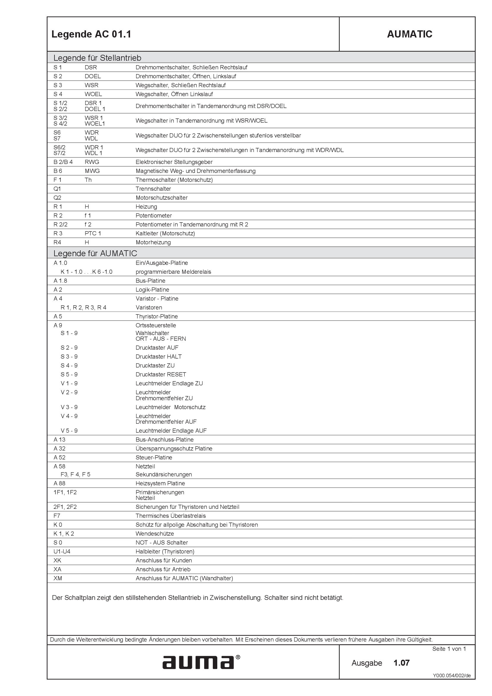
Legend AC 01.1
Wiring diagram
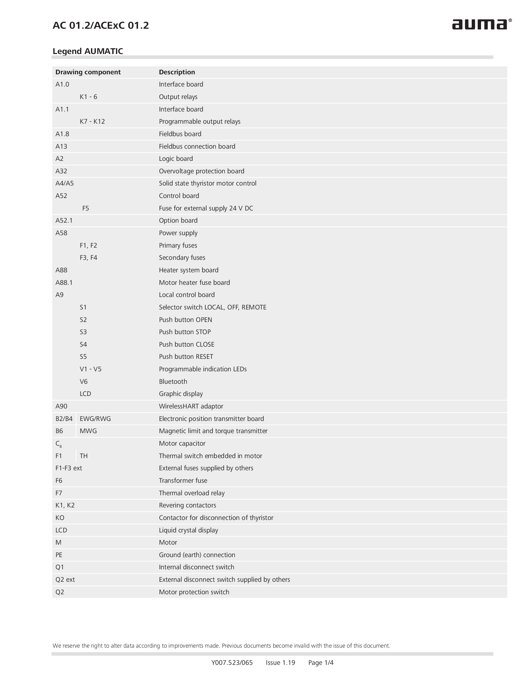
Legend AC 01.2/ACEx 01.2
Wiring diagram

Legend AC 01.2/ACEx 01.2, AC 01.2-SIL/ACExC 01.2-SIL
Wiring diagram
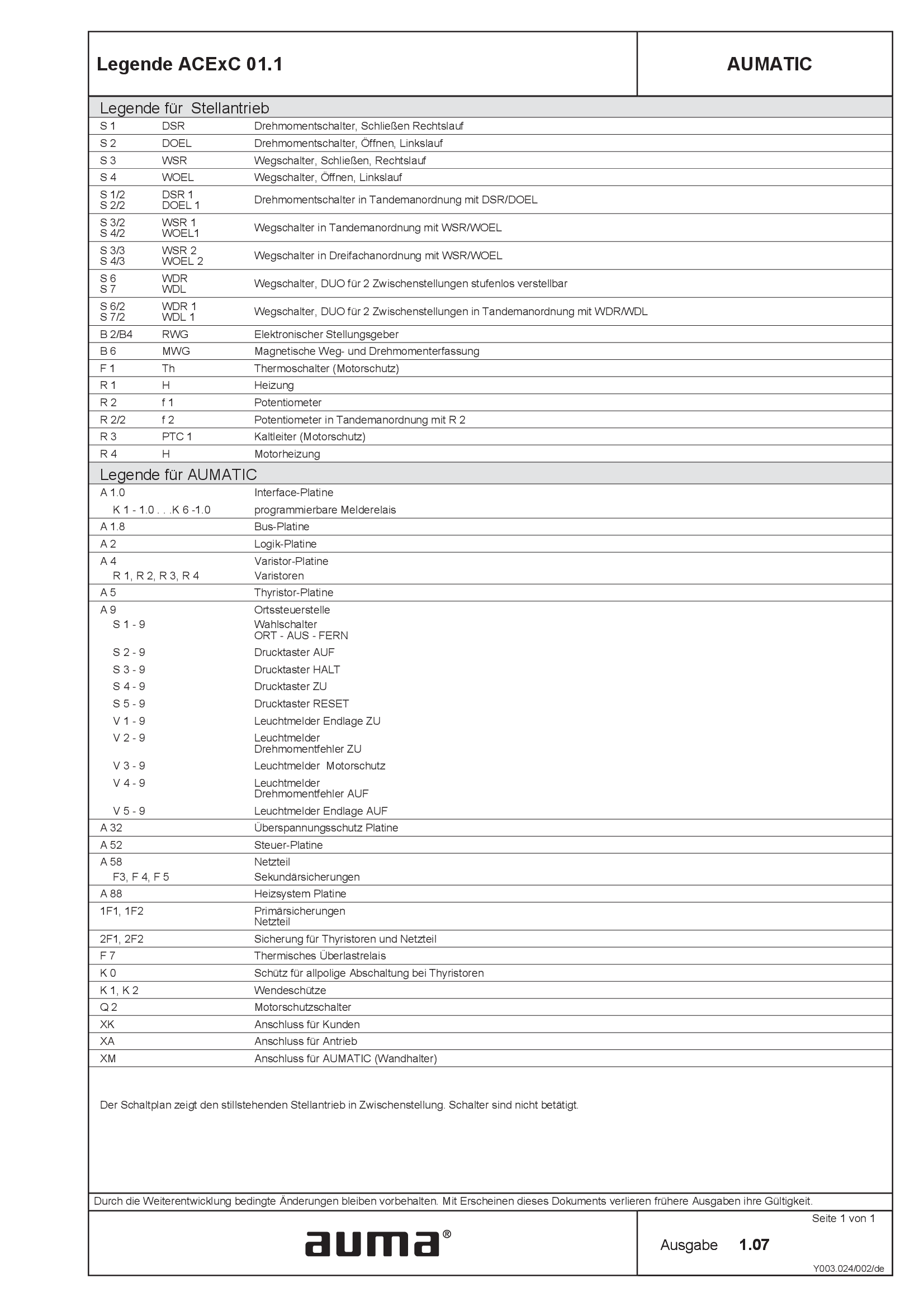
Legend ACExC01.1
Wiring diagram
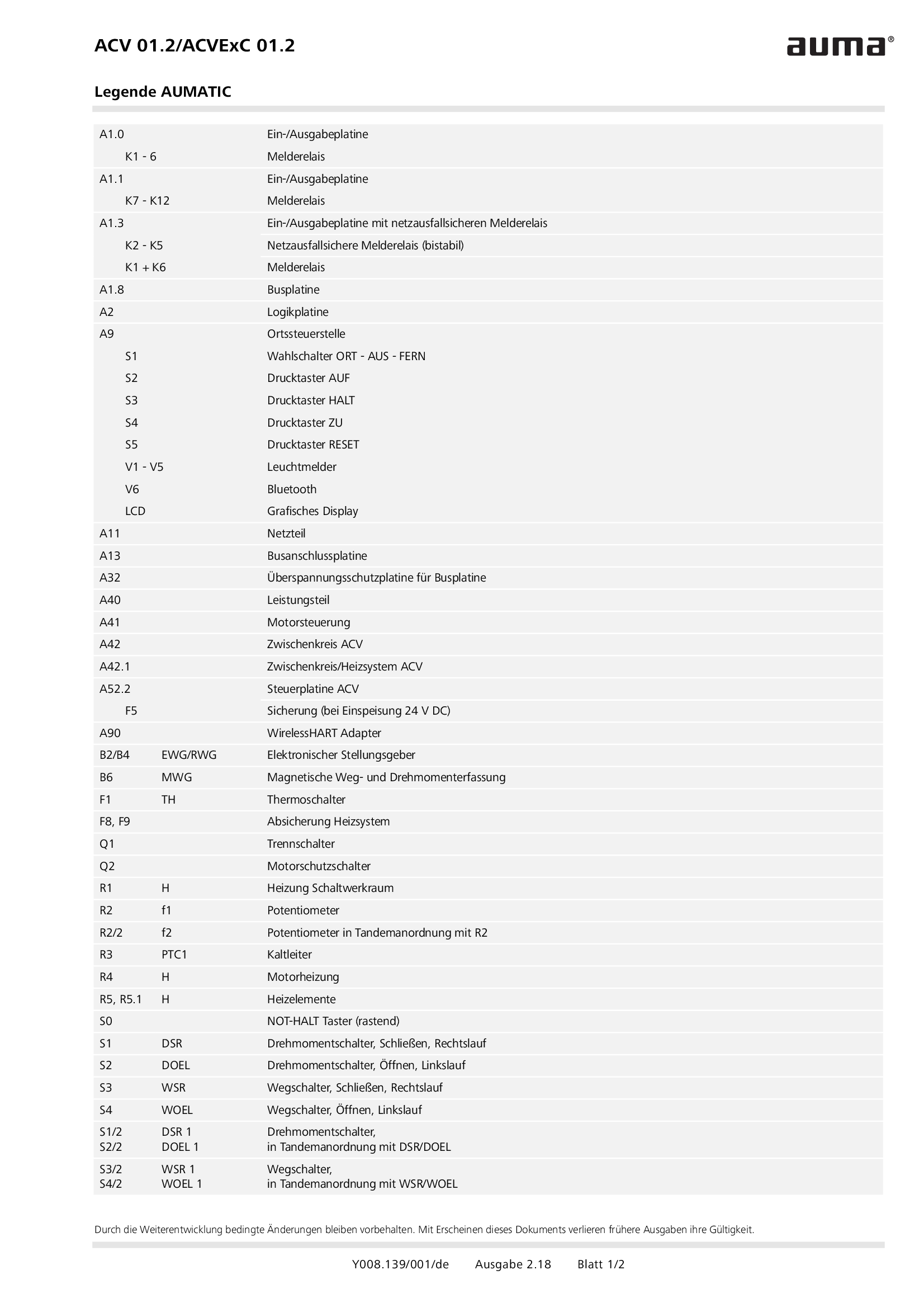
Legend ACV 01.2/ACVEx 01.2
Wiring diagram
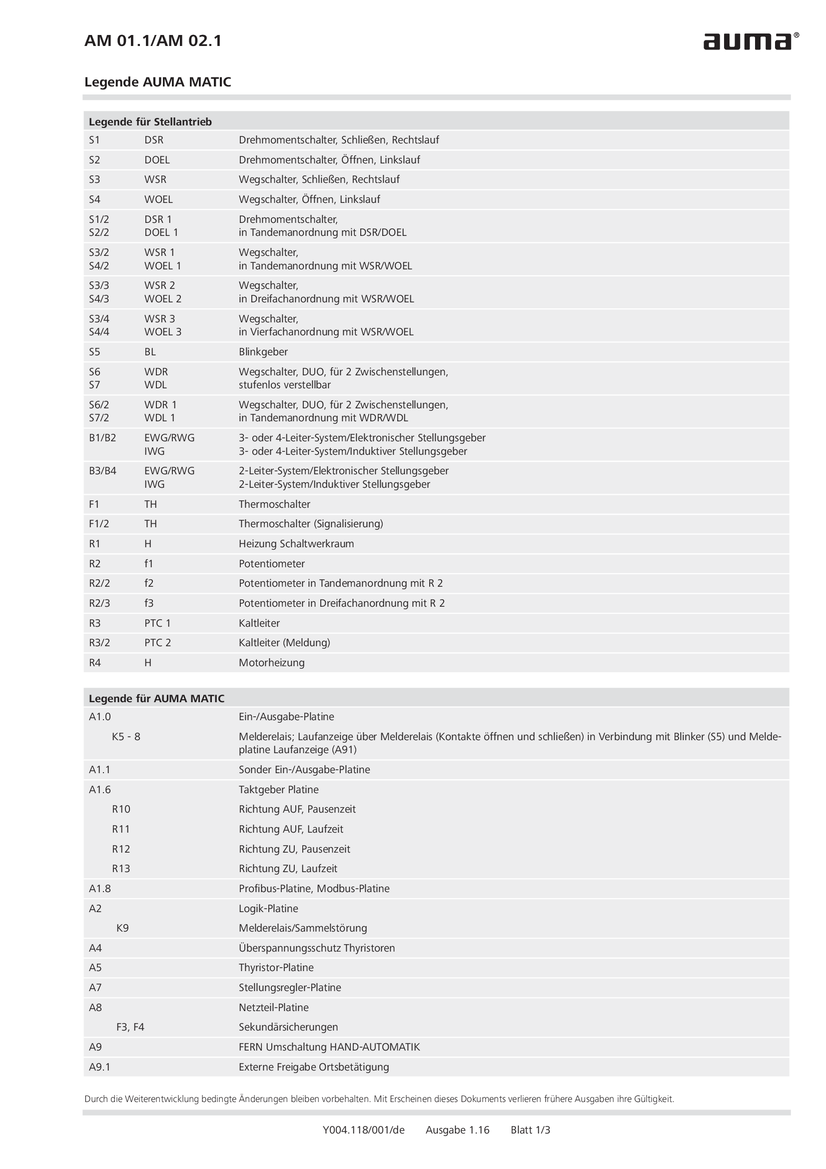
Legend AM 01.1/AM 02.1
Wiring diagram
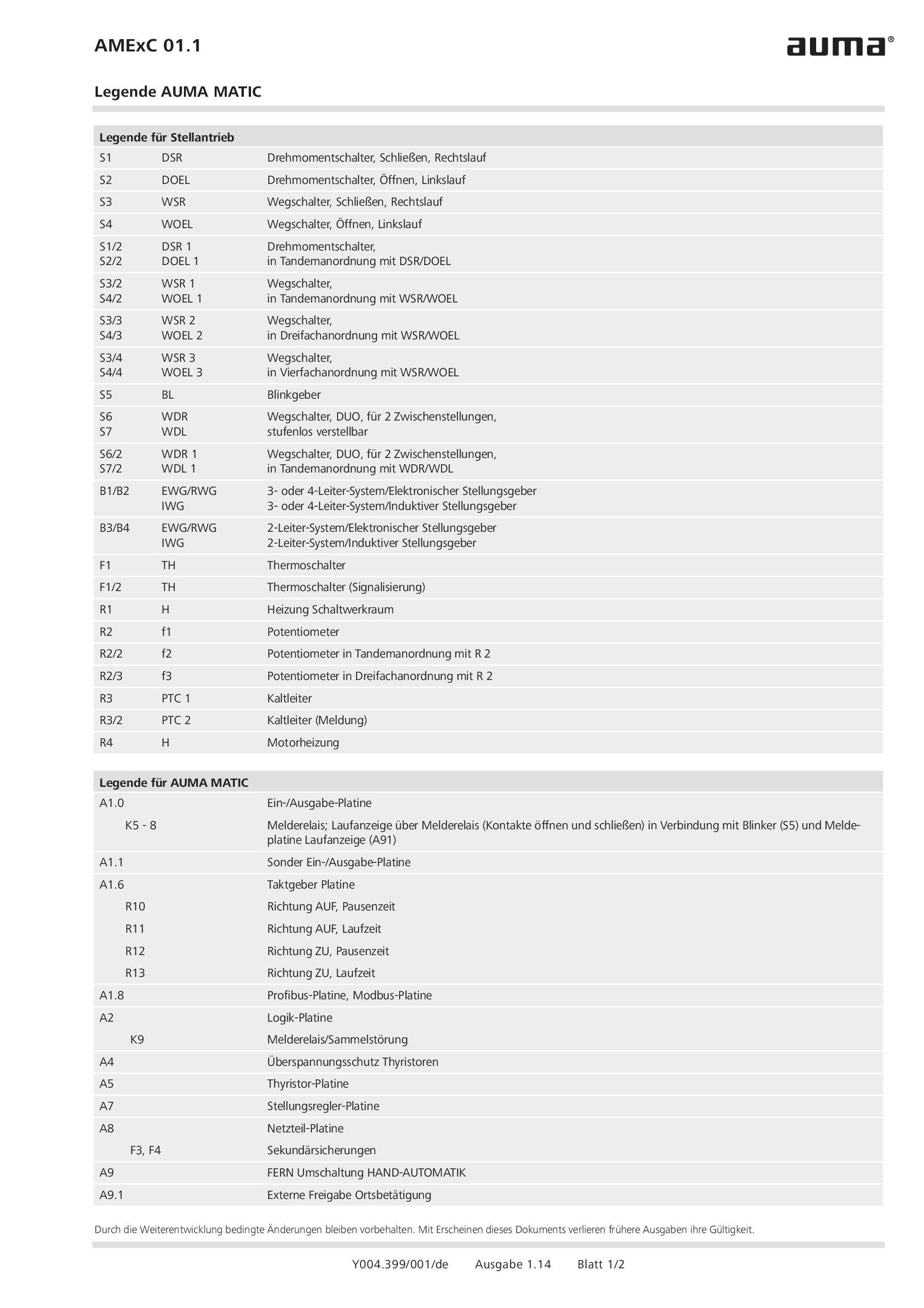
Legend AMExC 01.1
Wiring diagram

Legend SGC/SVC
Wiring diagram
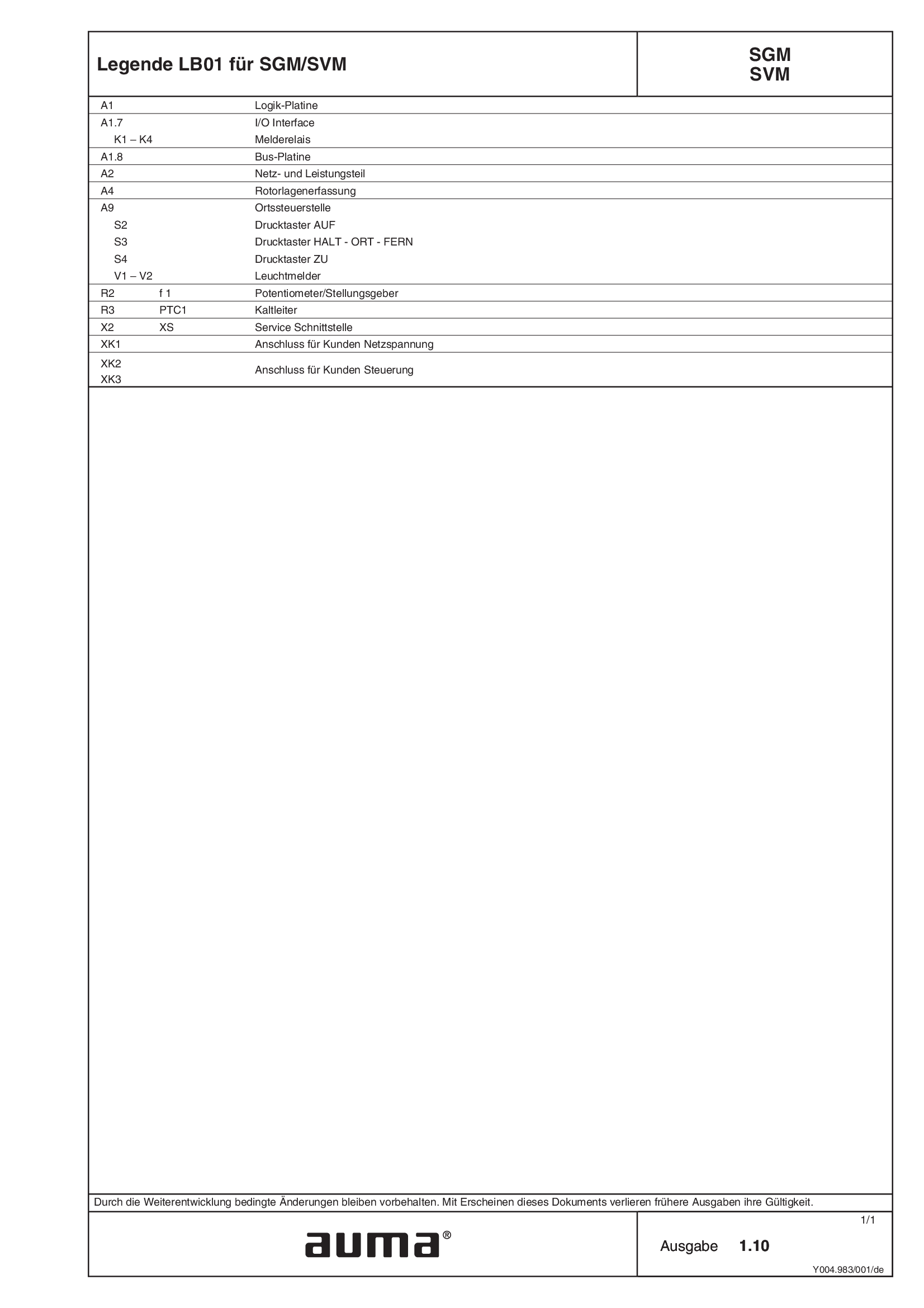
Legend SGM/SVM
Wiring diagram
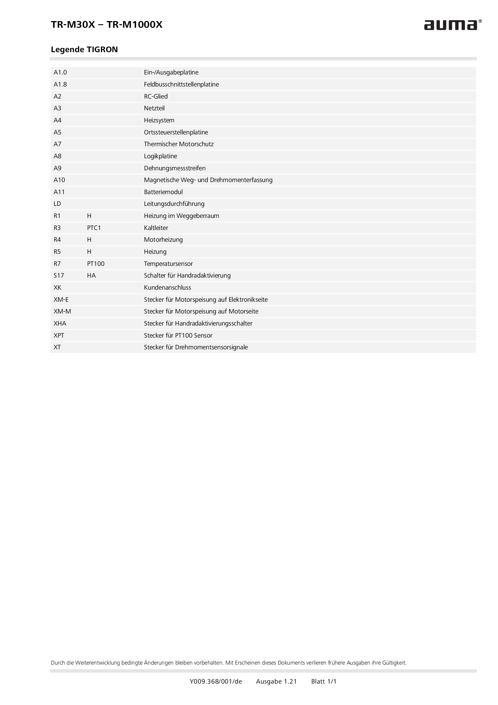
Legend TR-M30X – TR-M1000X
Wiring diagram
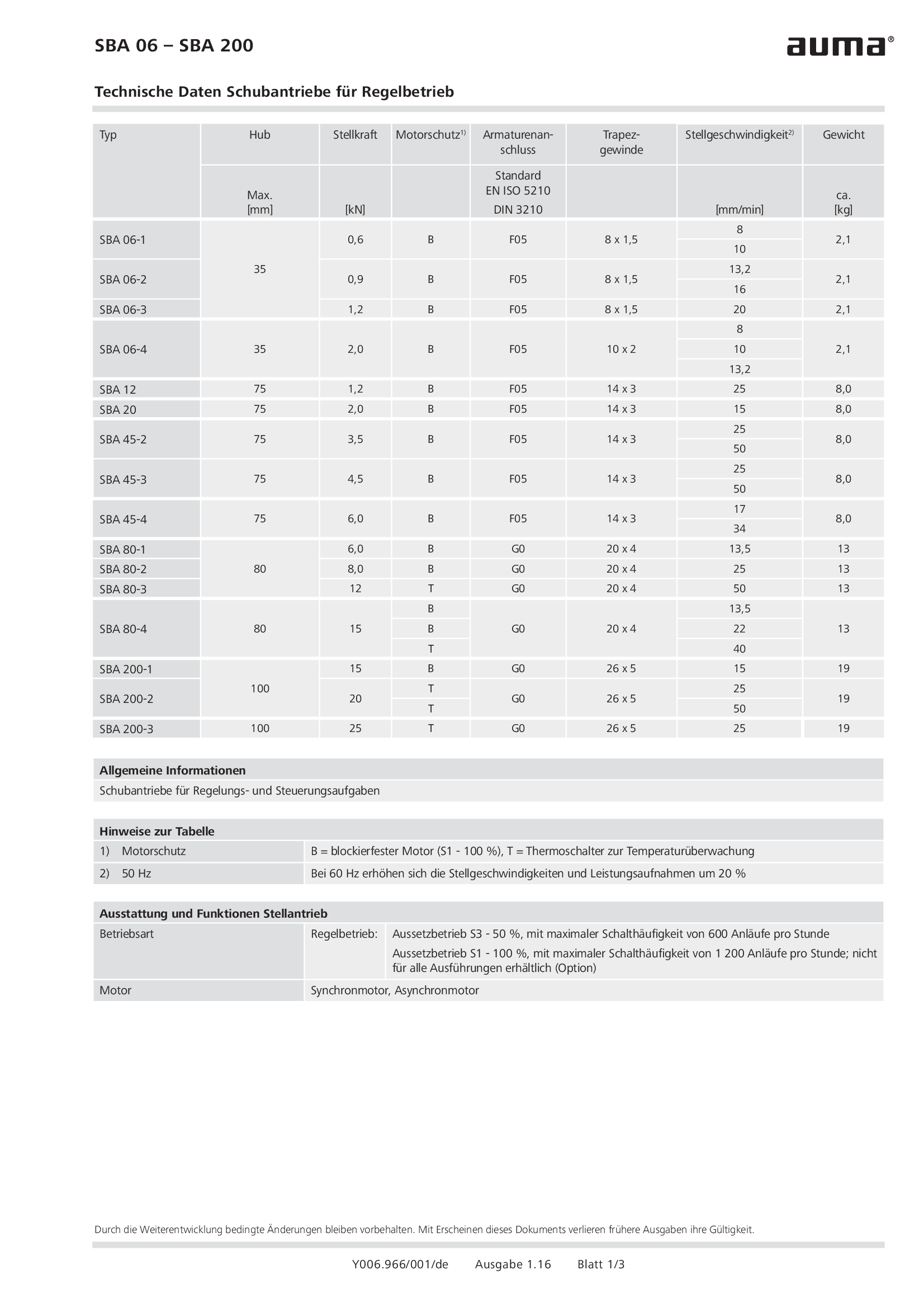
Linear actuators SBA 06 - 200 for modulating duty
Wiring diagram
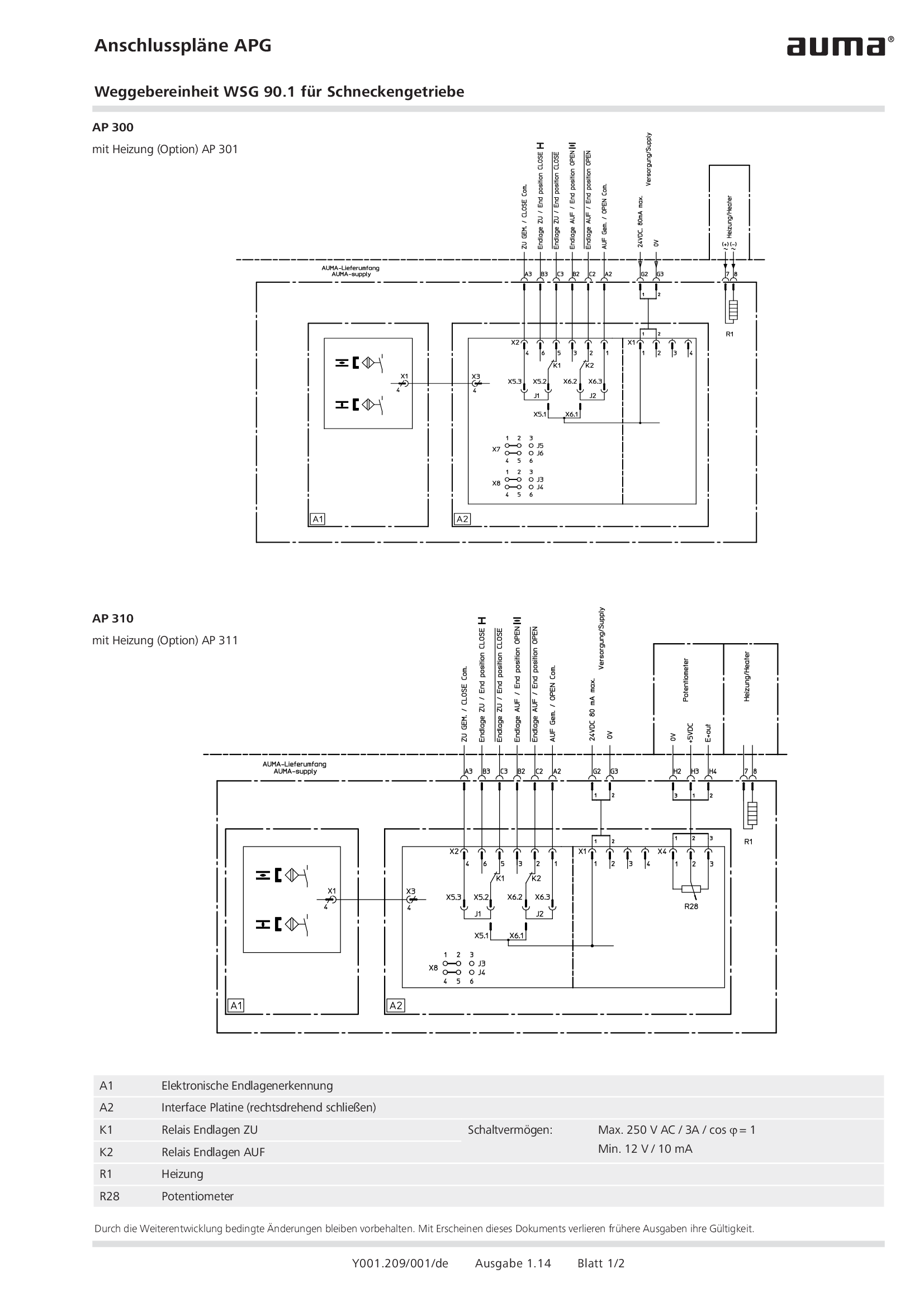
Overview terminal plans APG Valve position indicator WSG 90.1 for worm gearboxes
Wiring diagram
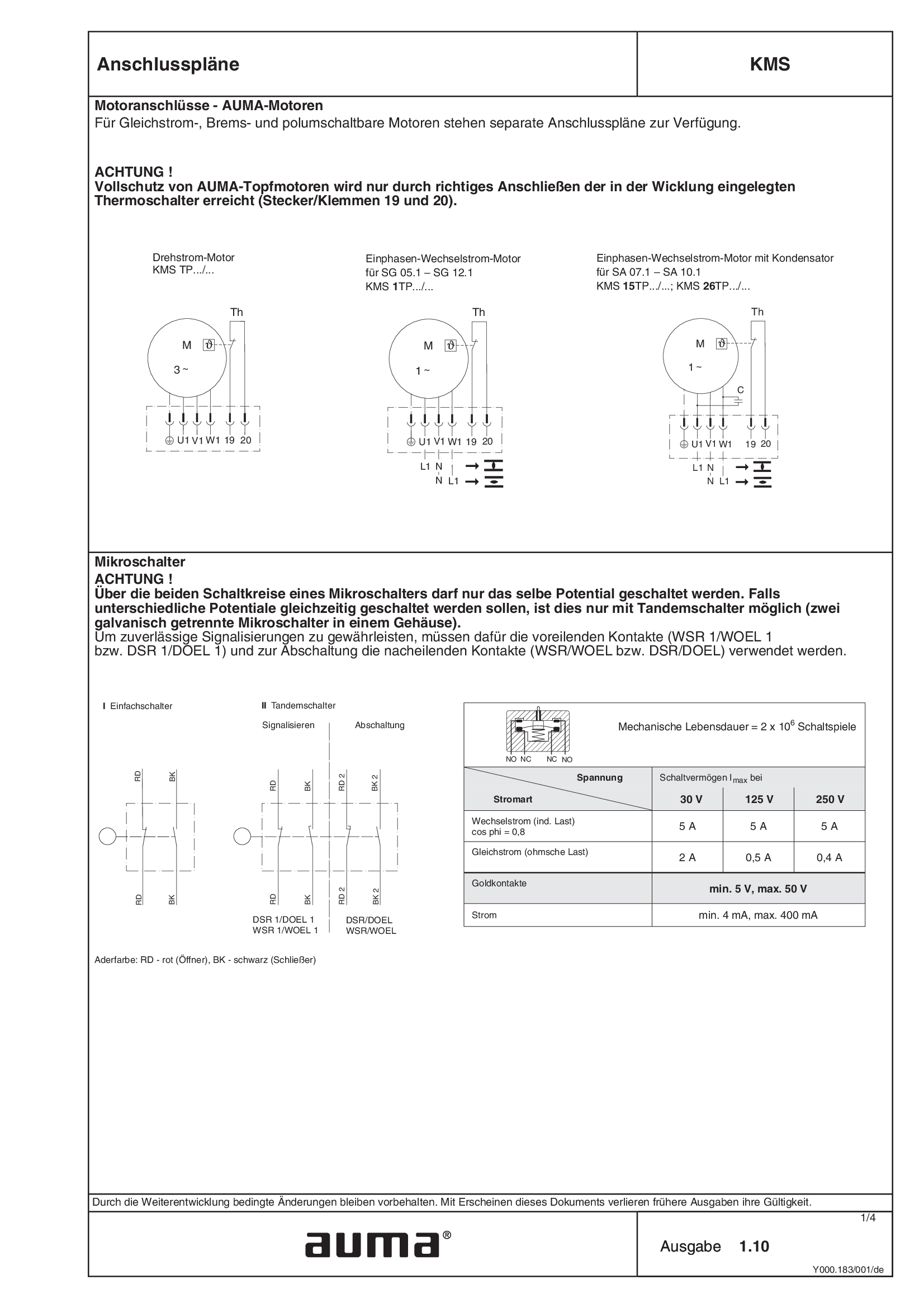
Overview terminal plans KMS
Wiring diagram
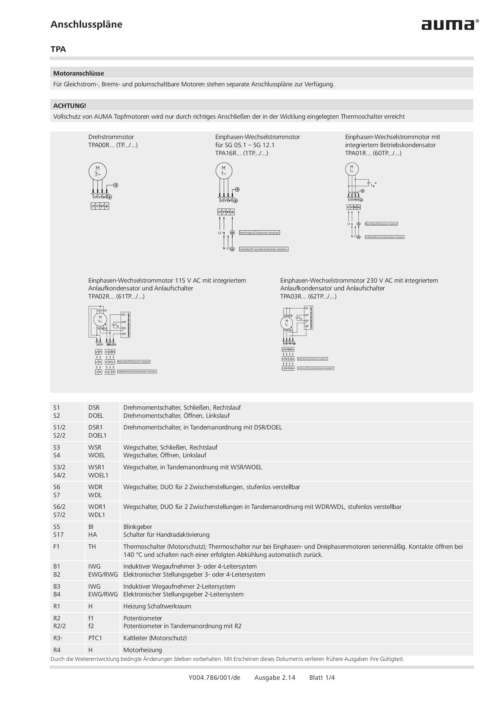
Overview terminal plans TPA
Wiring diagram

PROFOX PF-Q, PF-M, Modbus RTU
Wiring diagram

PROFOX PF-Q, PF-M, Profibus DP, with analogue input
Wiring diagram

PROFOX PF-Q, PF-M, Profibus DP, without analogue input
Wiring diagram

PROFOX PF-Q, PF-M, Profibus DP, without analogue input, direct current, 24 V DC
Wiring diagram

PROFOX PF-Q, PF-M, with analogue input
Wiring diagram

PROFOX PF-Q, PF-M, with analogue input, direct current, 24 V DC
Wiring diagram

PROFOX PF-Q, PF-M, without analogue input
Wiring diagram
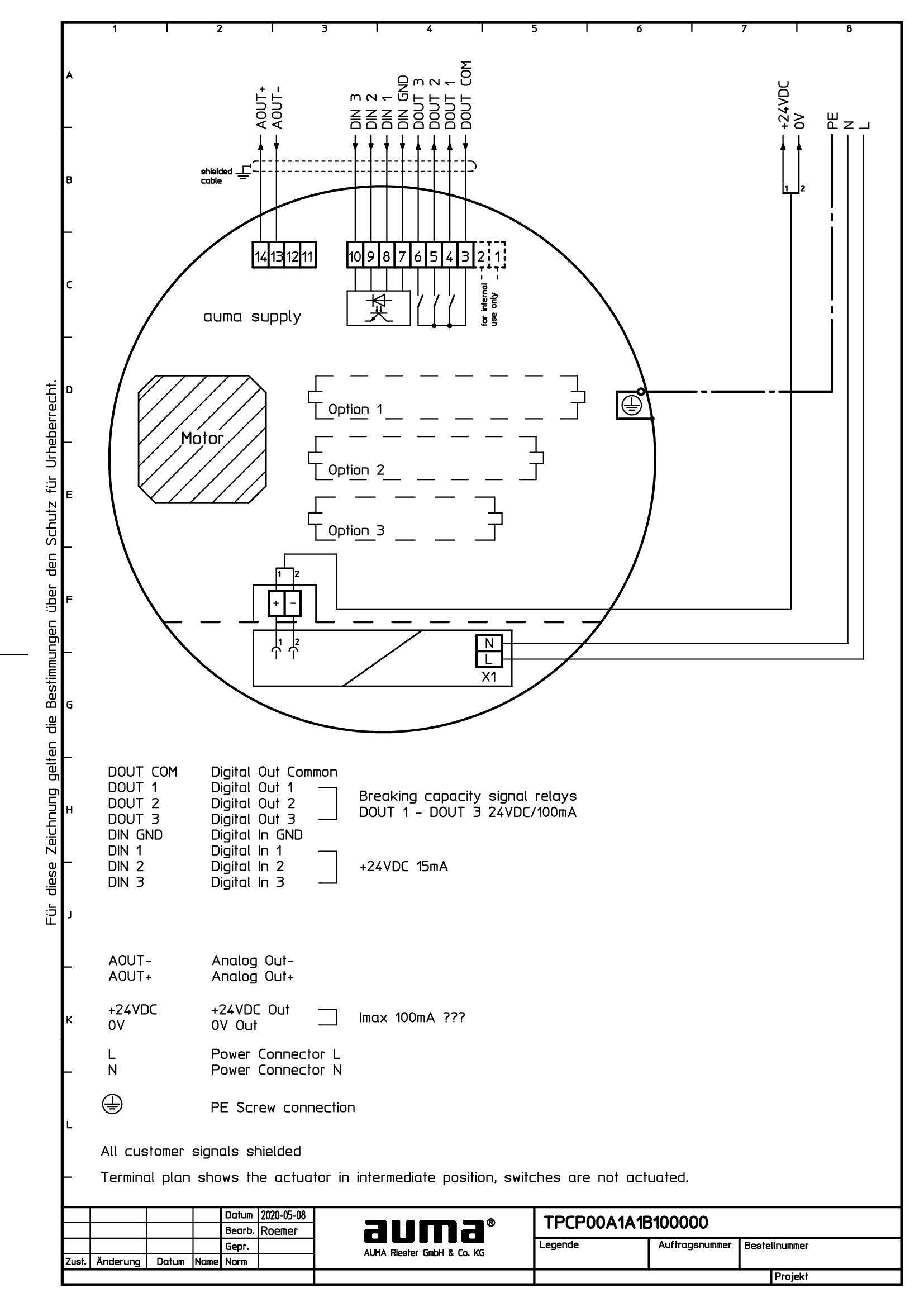
PROFOX PF-Q, PF-M, without analogue input, 24 V DC auxiliary voltage
Wiring diagram

PROFOX PF-Q, PF-M, without analogue input, direct current, 24 V DC
Wiring diagram
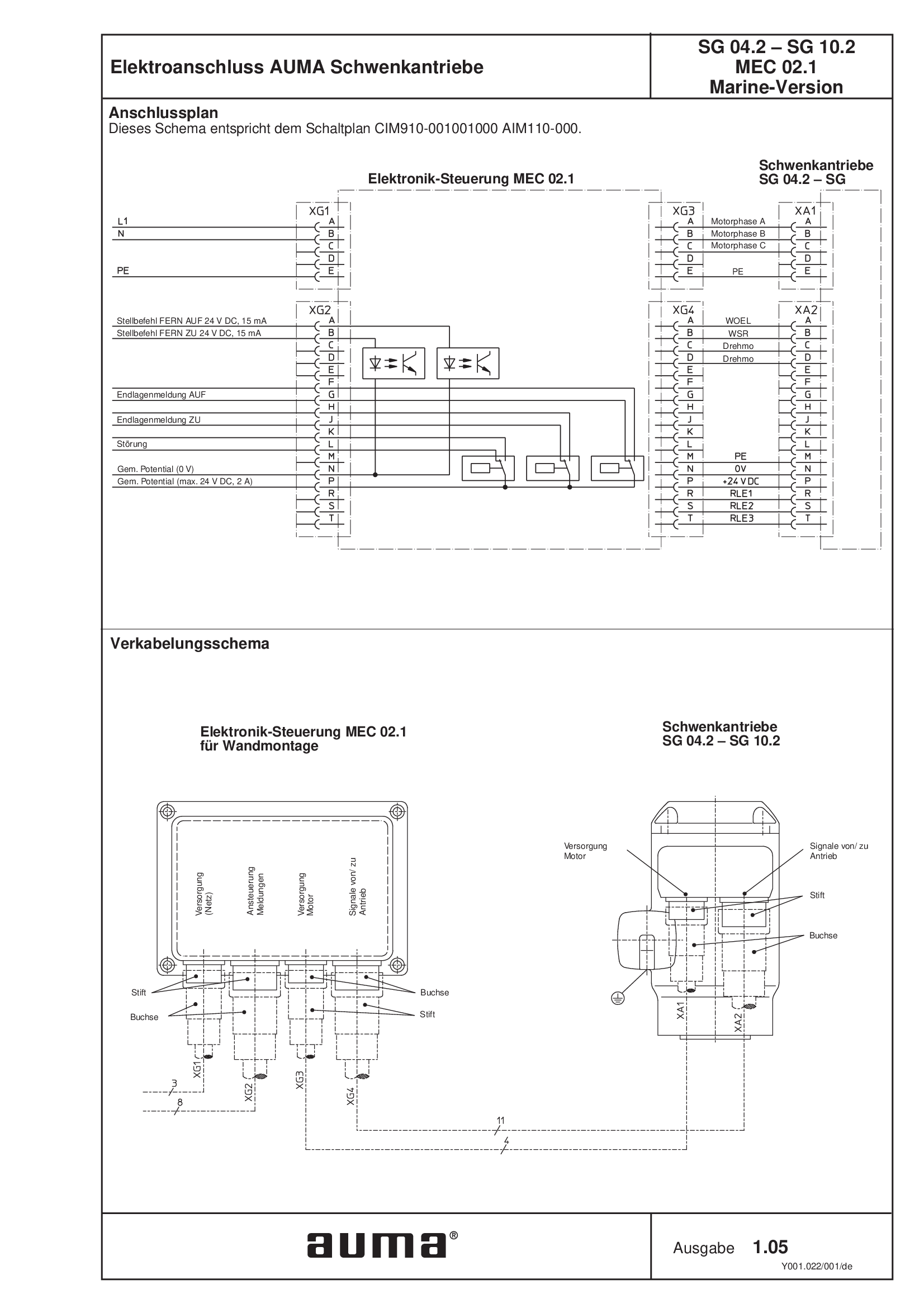
Part-turn actuators SG 04.2 - 10.2 MEC 02.1, military shipbuilding
Wiring diagram

Part-turn actuators SGC/SGCR, Valve actuators SVC/SVCR (basic version)
Wiring diagram

Part-turn actuators SGC/SGCR, Valve actuators SVC/SVCR, Profibus DP
Wiring diagram

Part-turn actuators SGCR, Valve actuators SVCR (with positioner)
Wiring diagram

Part-turn actuators SGM/SGMR, Valve actuators SVM/SVMR (basic version)
Wiring diagram

Part-turn actuators SGM/SGMR, Valve actuators SVM/SVMR, Profibus DP
Wiring diagram

Part-turn actuators SGMR, Valve actuators SVMR (with positioner)
Wiring diagram
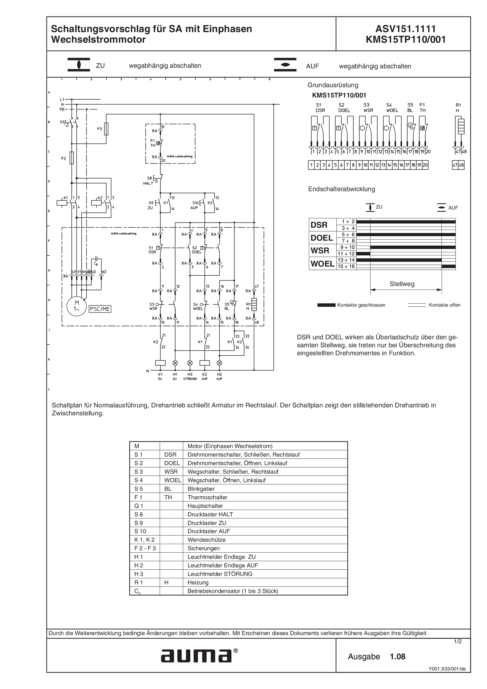
SA.1, 1-ph AC, ASV151.1111 /ASV151.1121 KMS15TP110/001
Wiring diagram
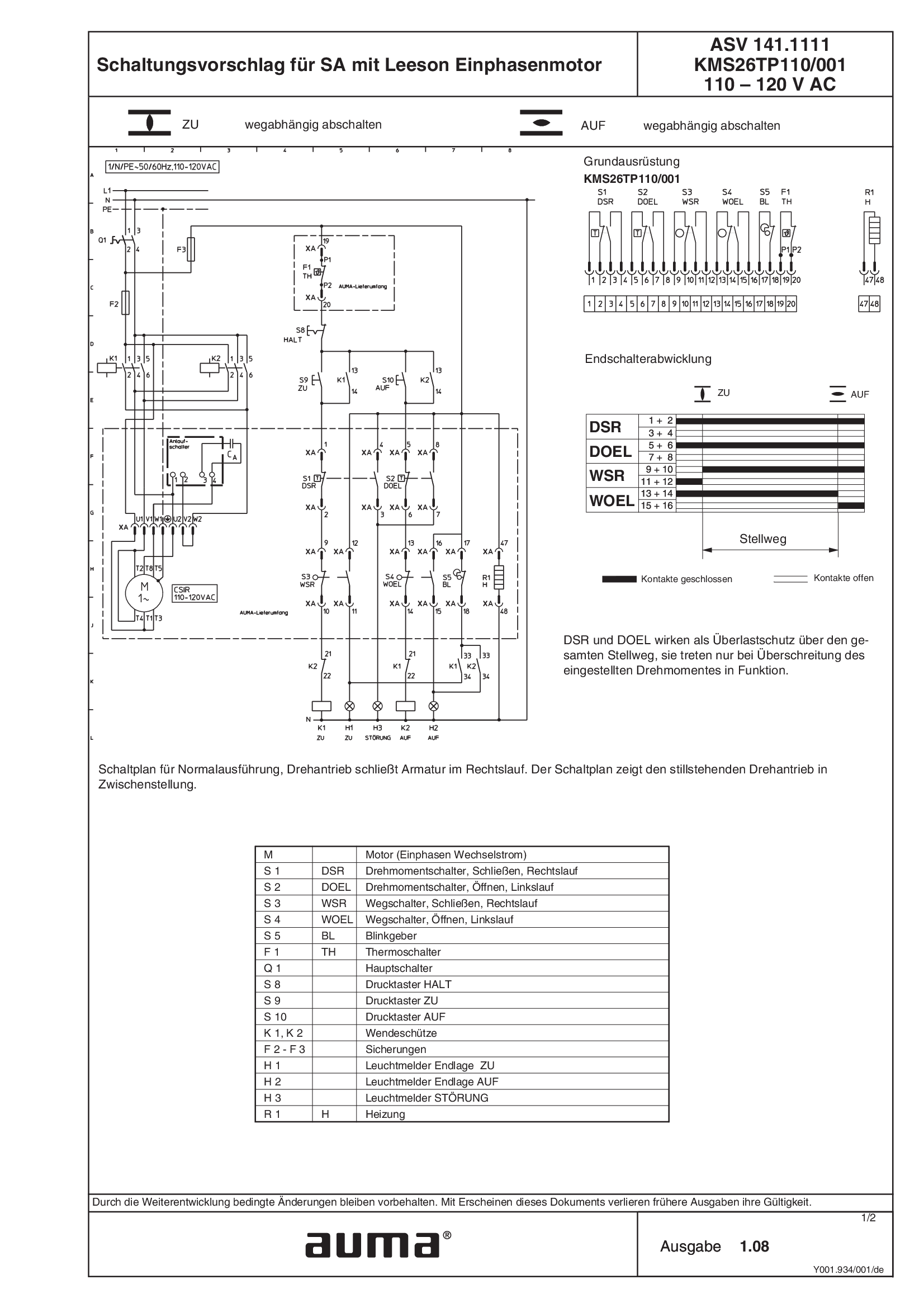
SA.1, 1-ph AC, Leeson motor ASV141.1111 /ASV141.1121 KMS26TP110/001 110 - 120 V AC
Wiring diagram
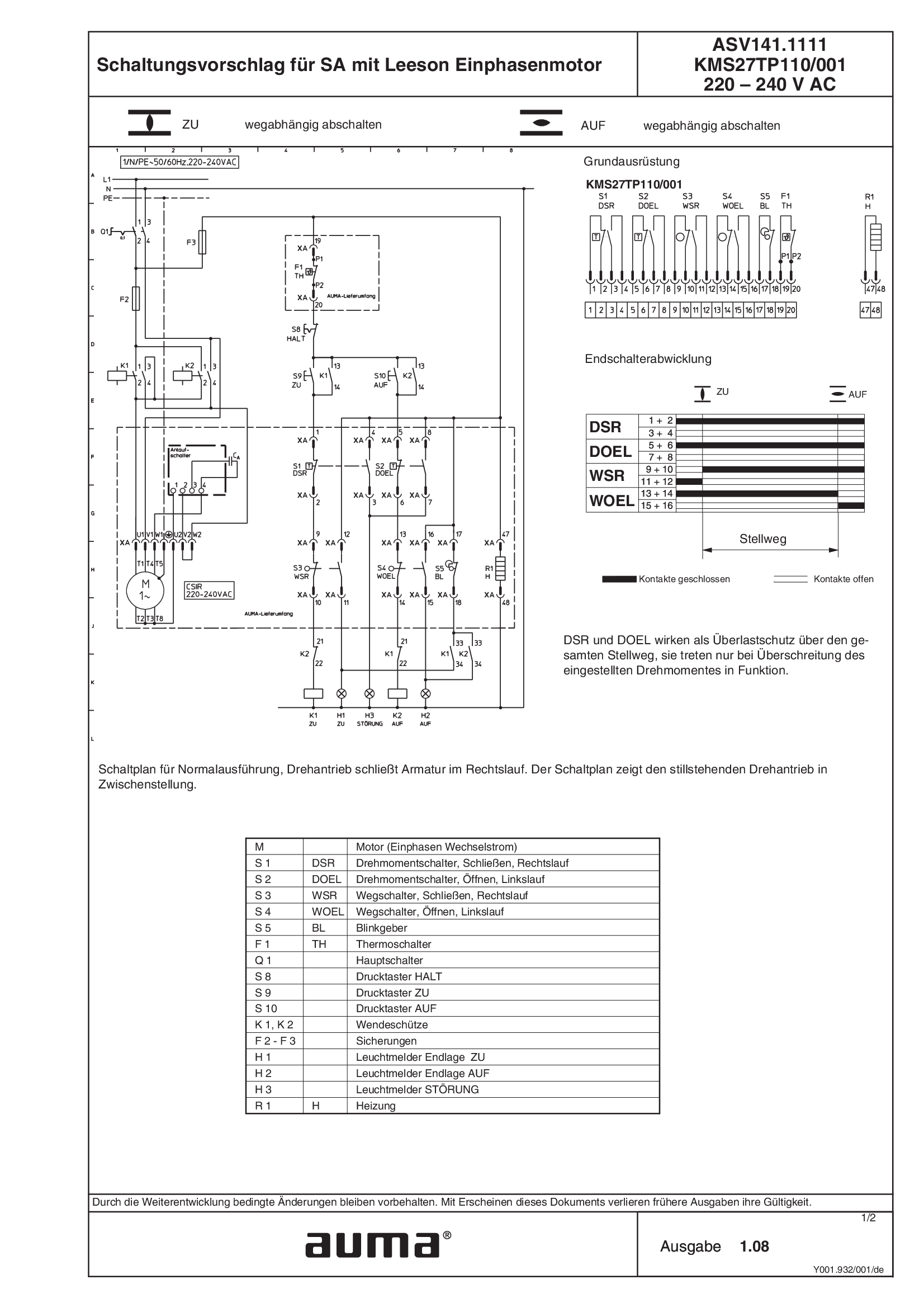
SA.1, 1-ph AC, Leeson motor ASV141.1111 /ASV141.1121 KMS27TP110/001 220 - 240 V AC
Wiring diagram
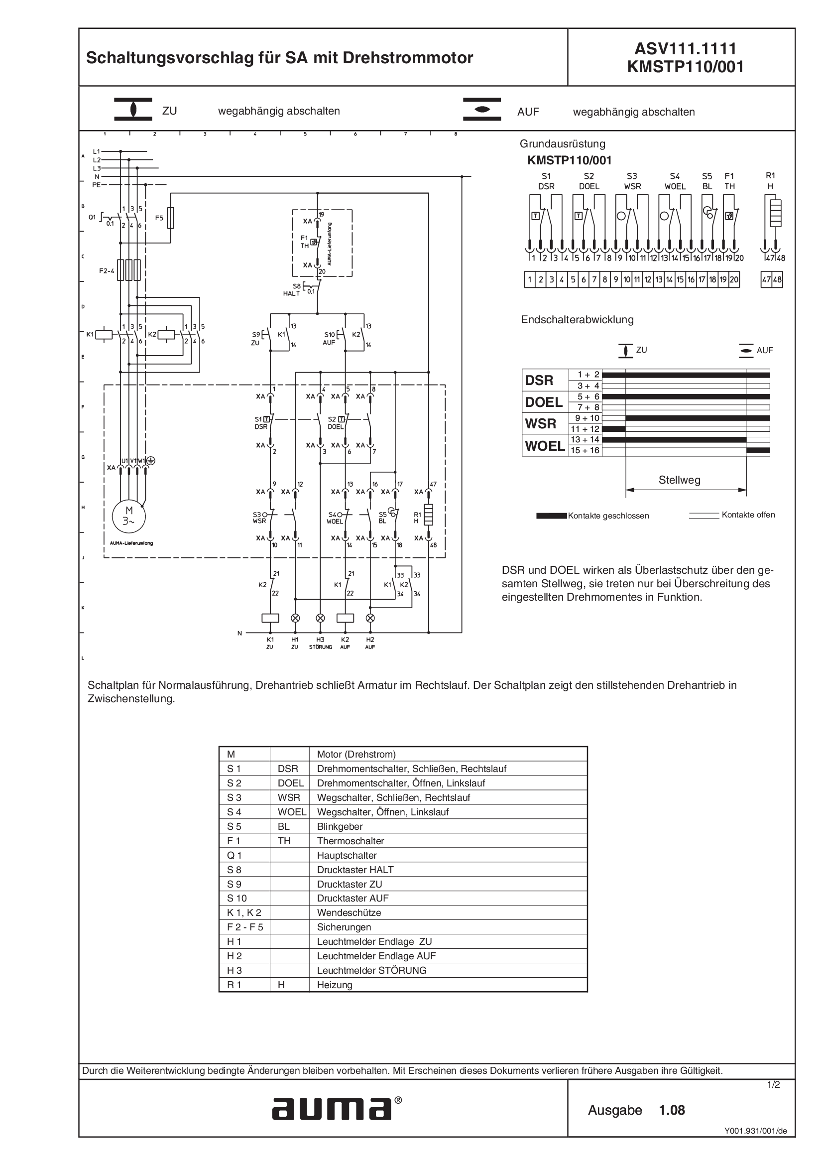
SA.1, 3-ph AC ASV111.1111 /ASV111.1121 KMSTP110/001
Wiring diagram
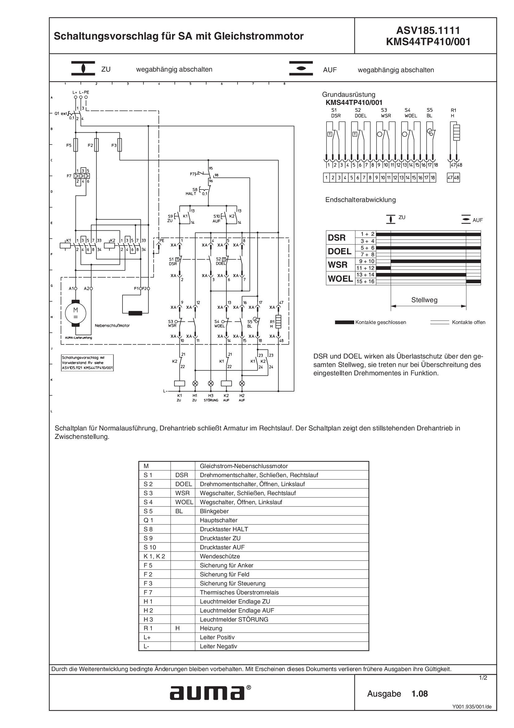
SA.1, DC ASV185.1111 /ASV185.1121 KMSTP410/001
Wiring diagram
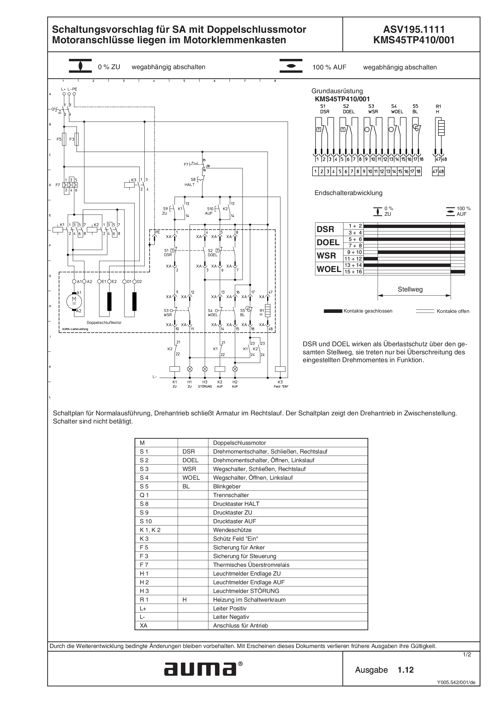
SA.1, DC ASV195.1111/ASV195.1121 KMS45TP410/001, compound motor, motor connections with motor terminal box
Wiring diagram

SA.1, DC ASV195.1111/ASV195.1121 KMS63TP410/001, compound motor, motor connection with plug/socket connector
Wiring diagram
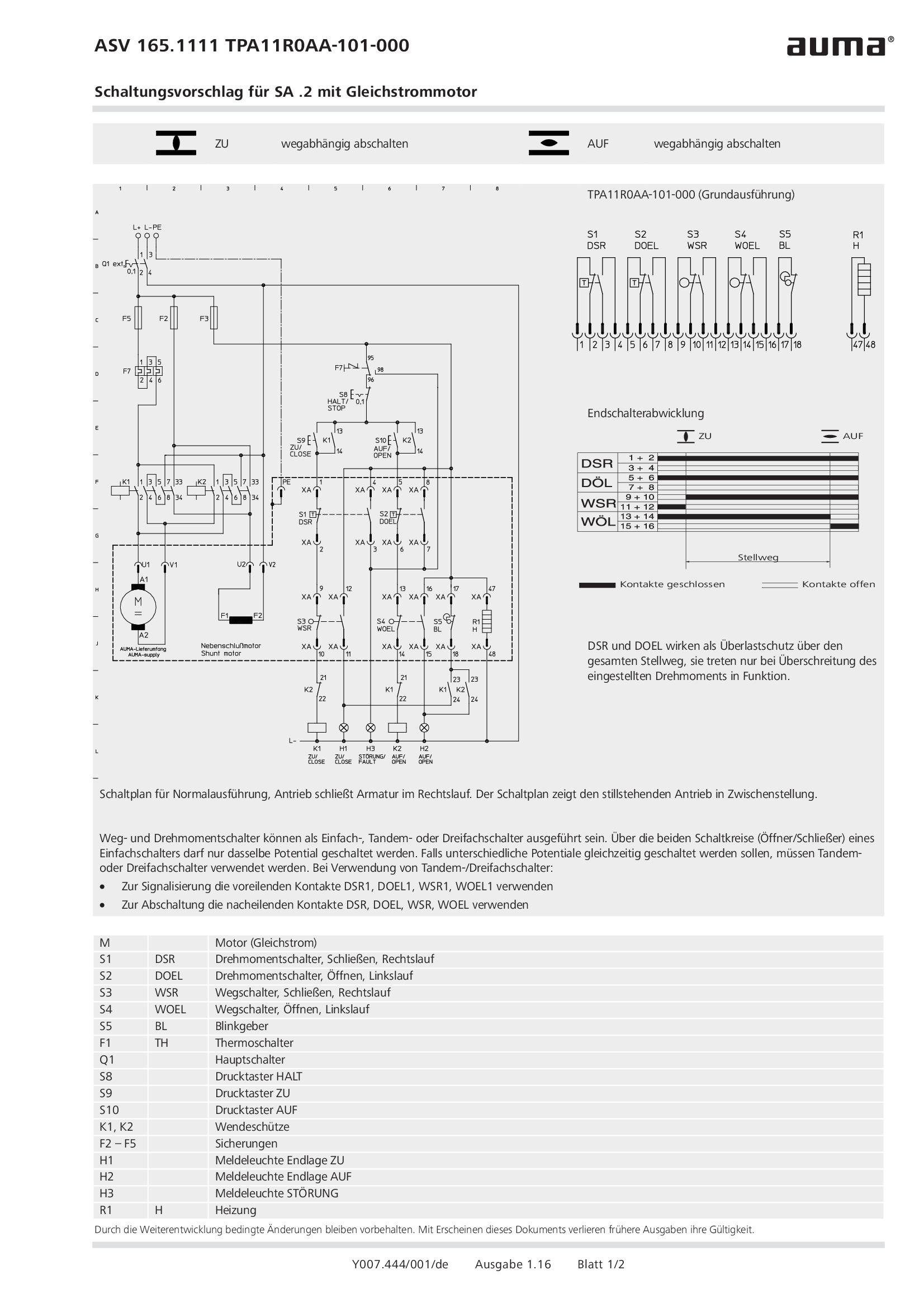
SA.2, DC ASV165.1111 /ASV165.1121 TPA11R0AA-101-000
Wiring diagram
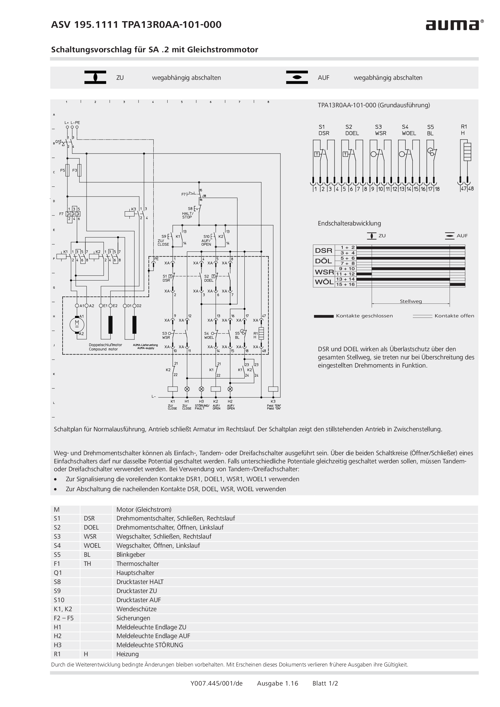
SA.2, DC ASV195.1111 /ASV195.1121 TPA13R0AA-101-000
Wiring diagram
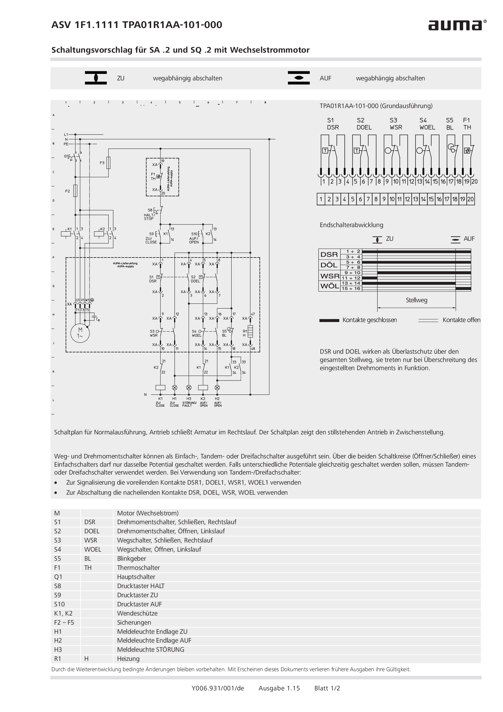
SA.2/SQ.2, 1-ph AC ASV1F1.1111 /ASV1F1.1121 TPA01R1AA-101-000
Wiring diagram
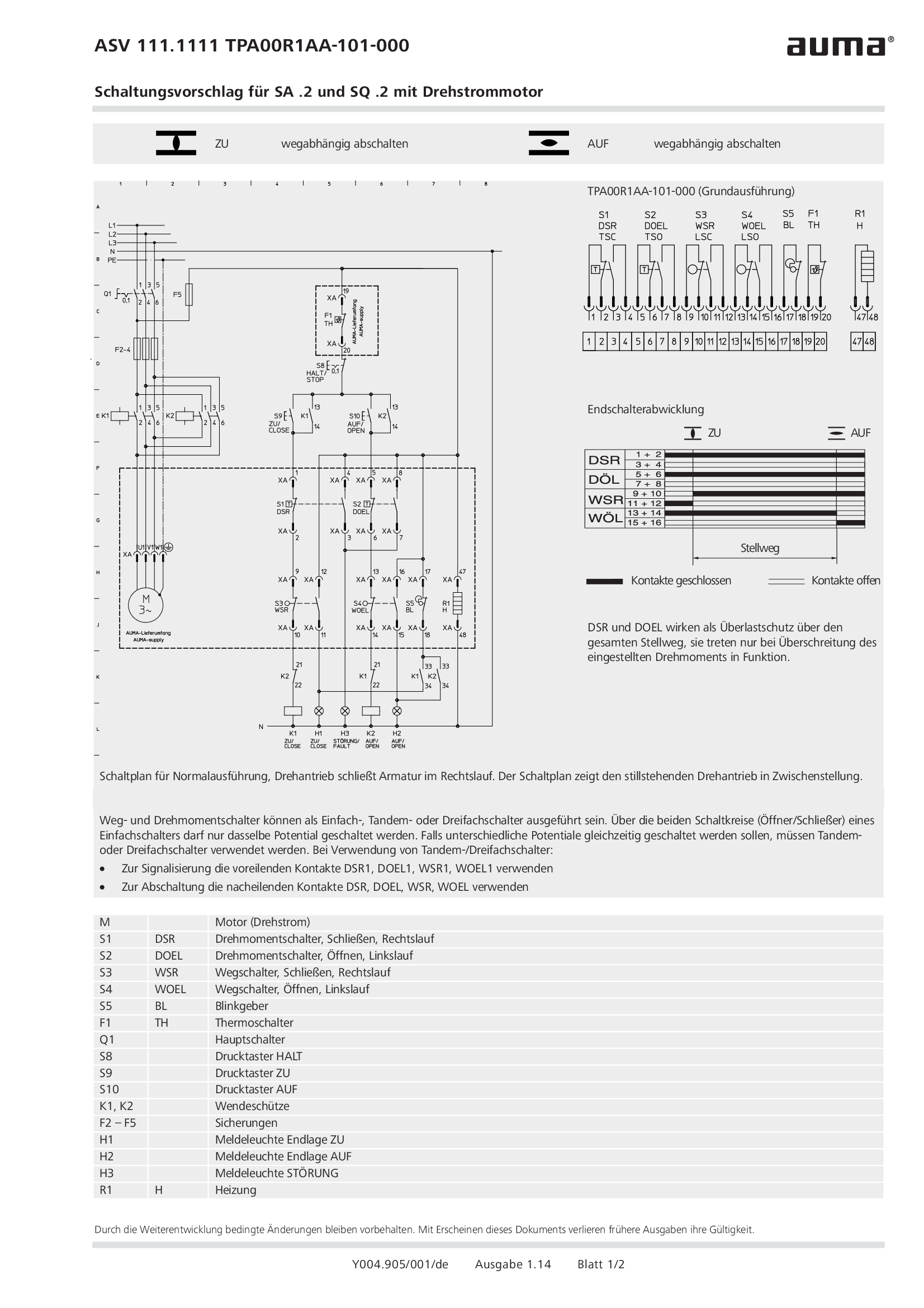
SA.2/SQ.2, 3-ph AC ASV111.1111 /ASV111.1121 TPA00R1AA-101-000
Wiring diagram
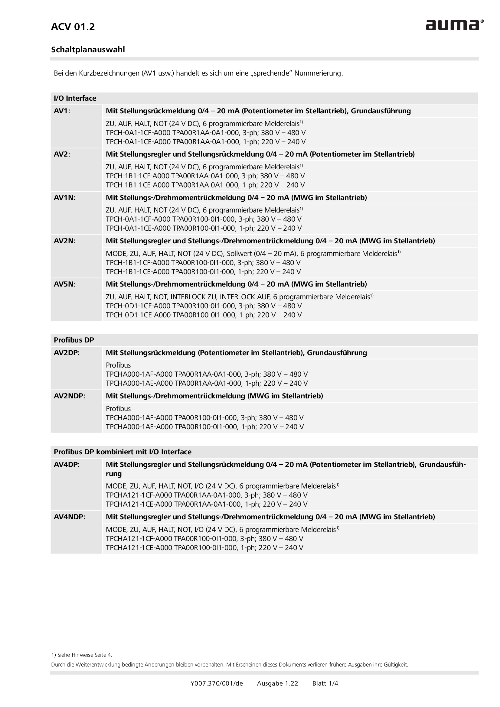
Selection for wiring diagram for ACV 01.2
Wiring diagram
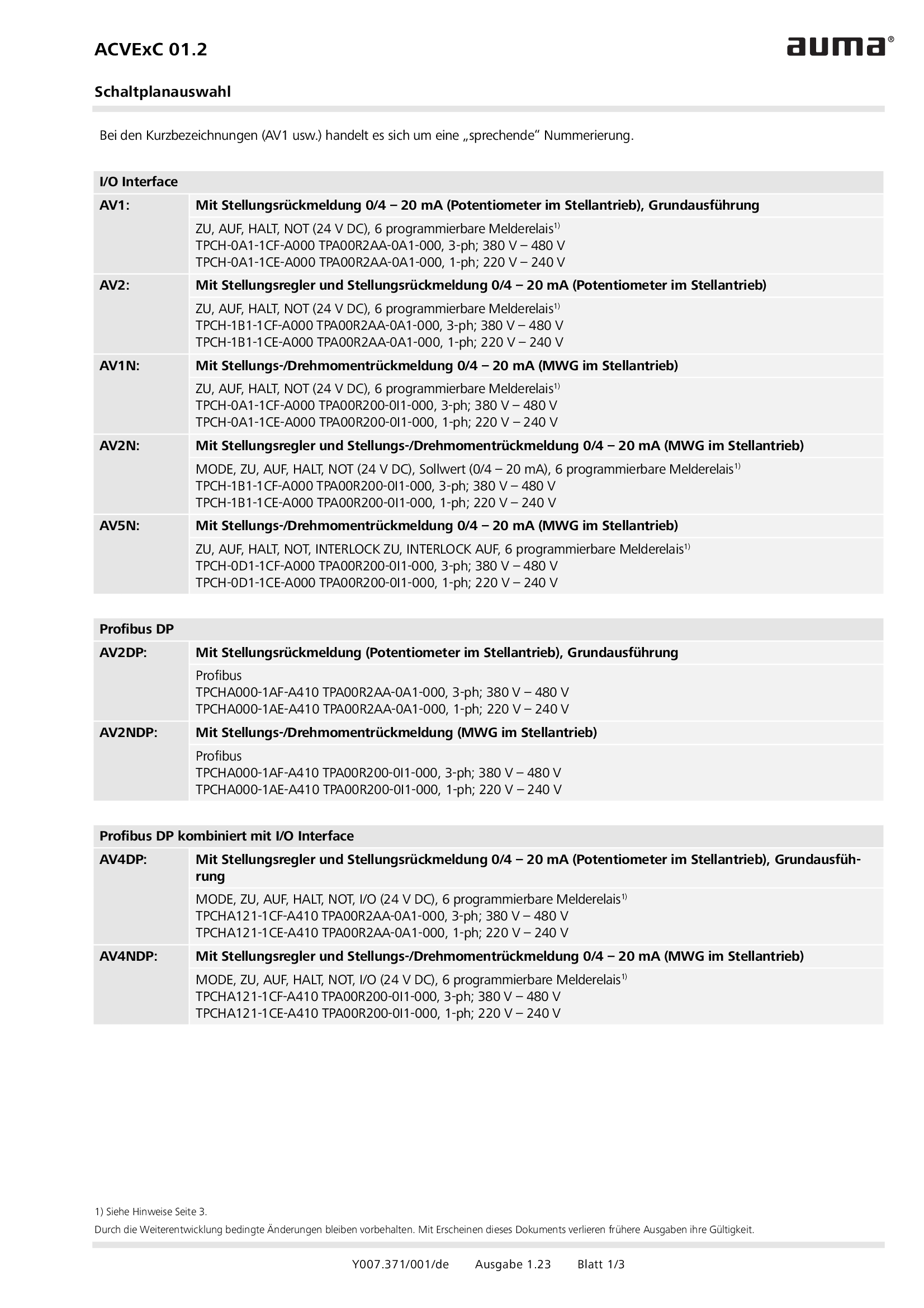
Selection for wiring diagram for ACVExC 01.2
Wiring diagram
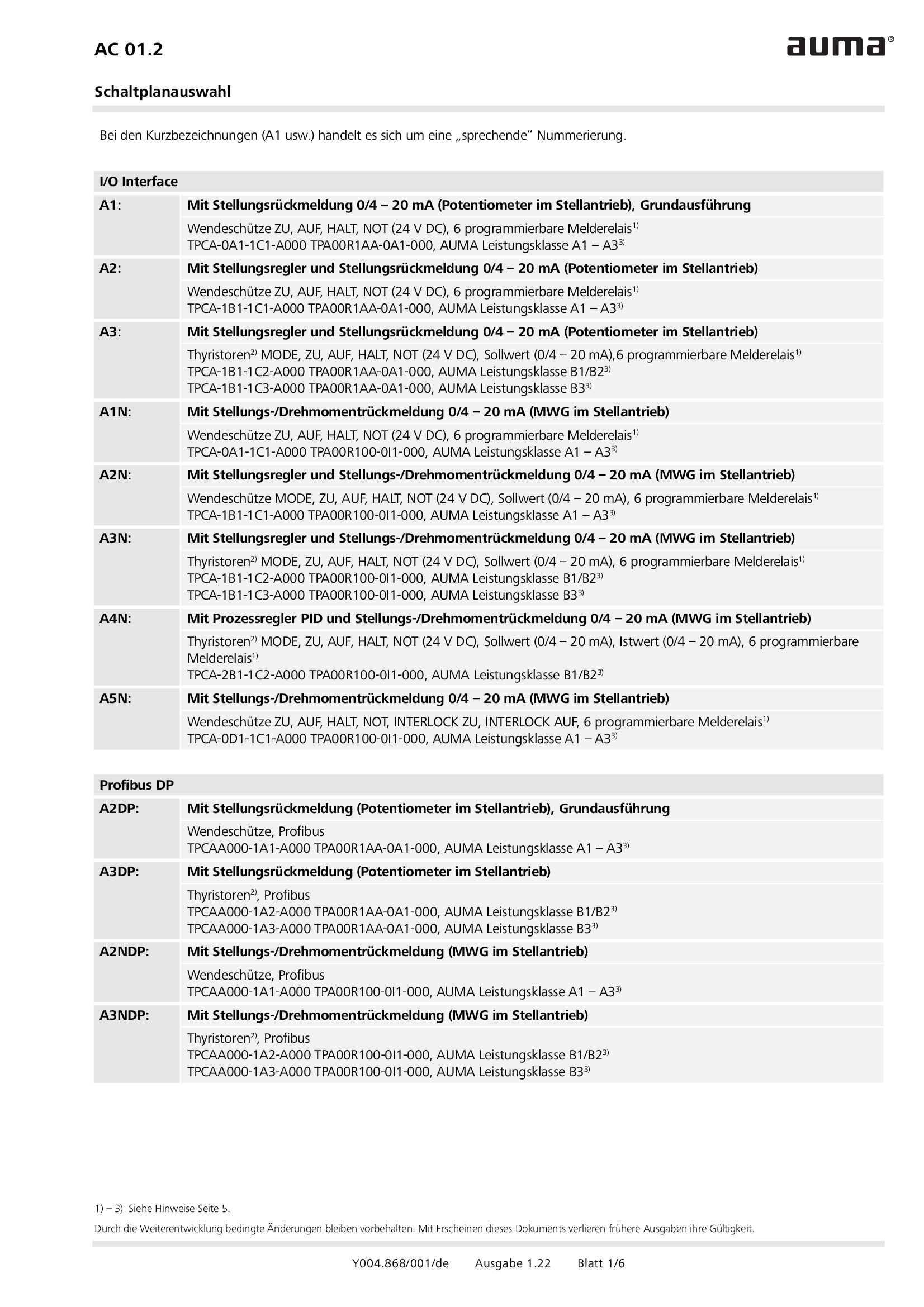
Selection for wiring diagram for AUMATIC AC 01.2
Wiring diagram
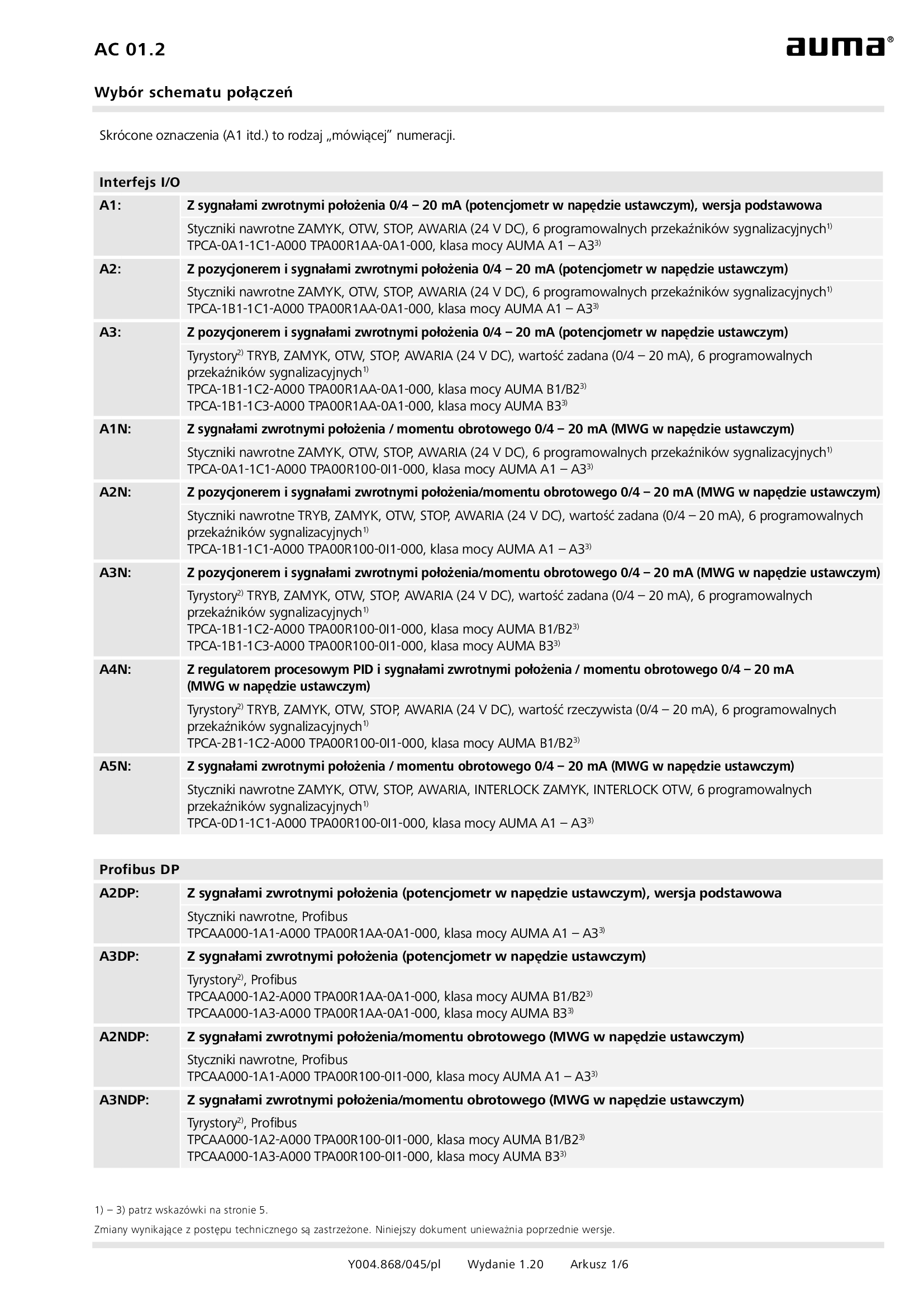
Selection for wiring diagram for AUMATIC AC 01.2/ACExC 01.2
Wiring diagram
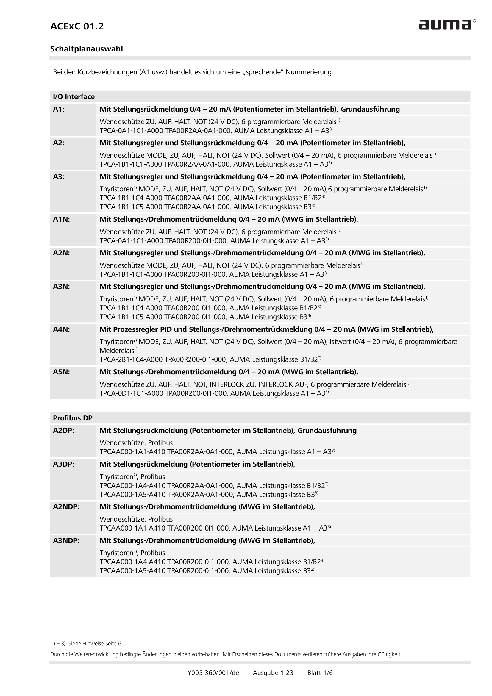
Selection for wiring diagram for AUMATIC ACExC 01.2
Wiring diagram
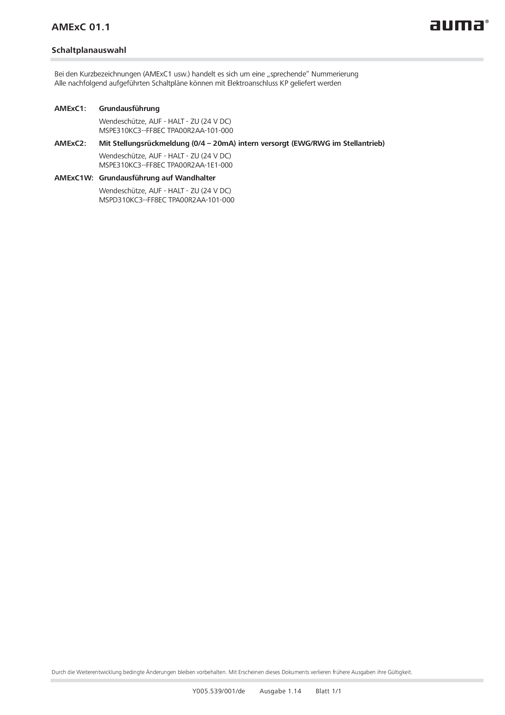
Selection of wiring diagrams for AUMA MATIC AMExC
Wiring diagram
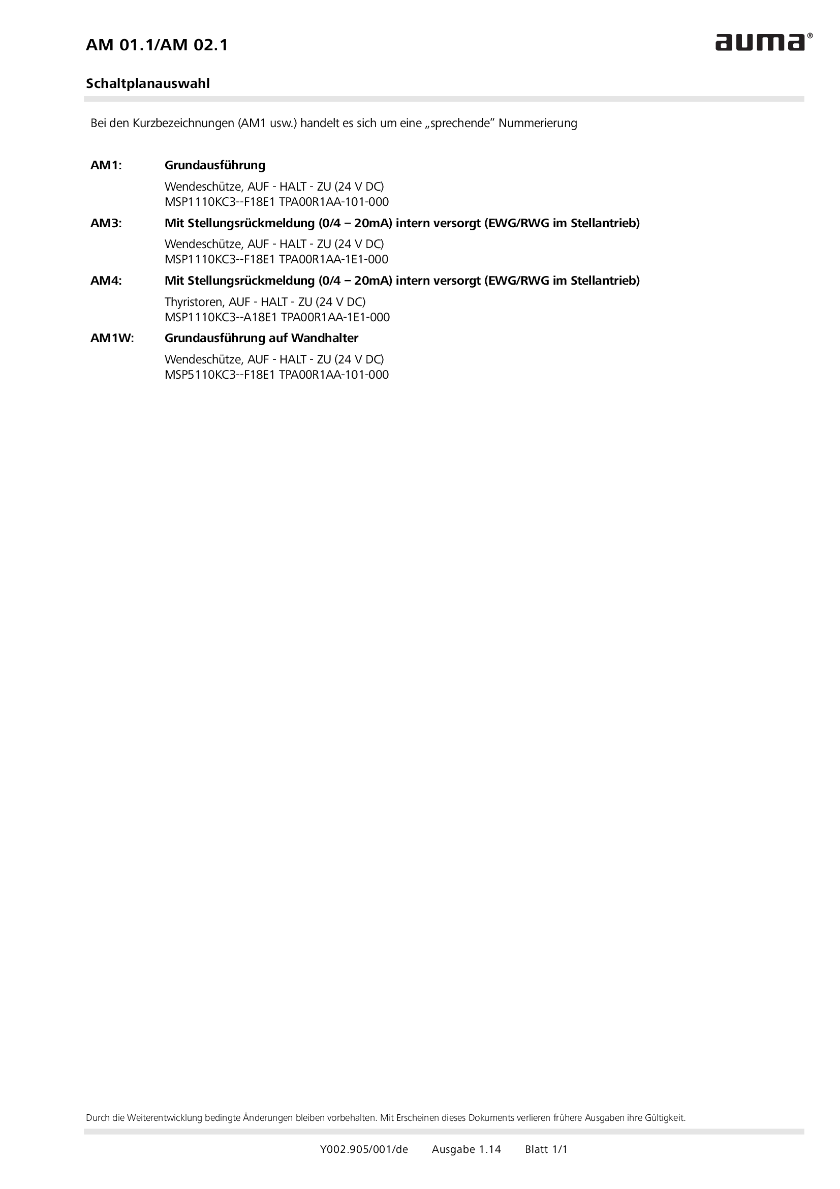
Selection of wiring diagrams for MATIC AM 01.1/AM 02. 1
Wiring diagram
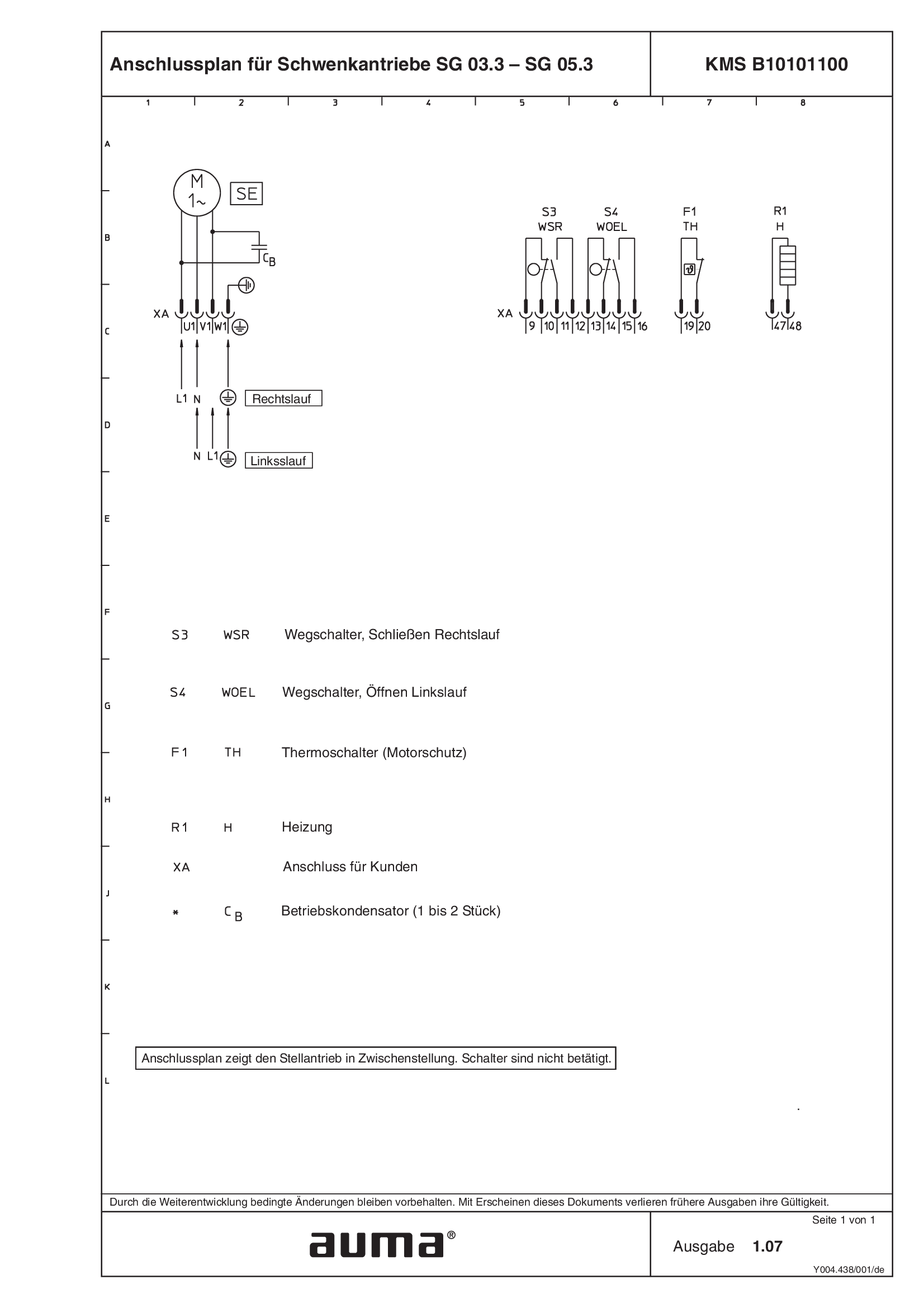
Terminal plan SG.3 - KMS B10101100
Wiring diagram

Terminal plans KMS, SA(R)N 07.1 - 25.1
Wiring diagram
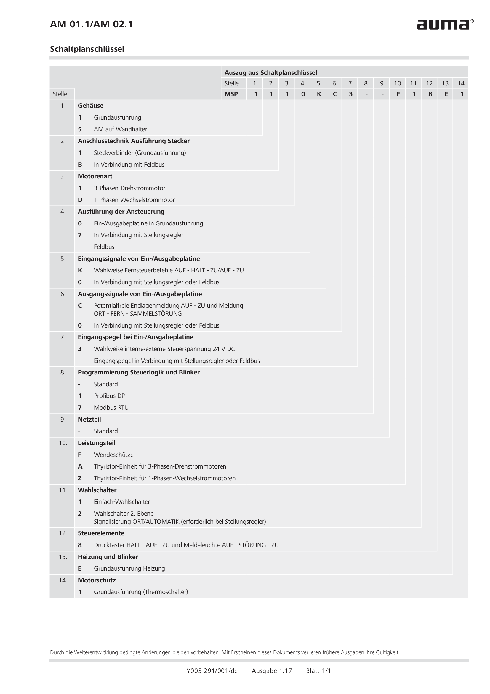
Wiring diagram code AM 01.1/AM 02.1
Wiring diagram
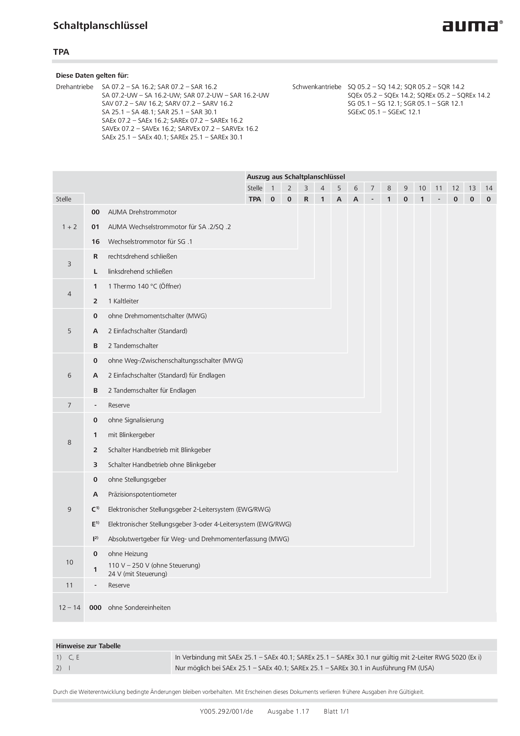
Wiring diagram code TPA
Wiring diagram
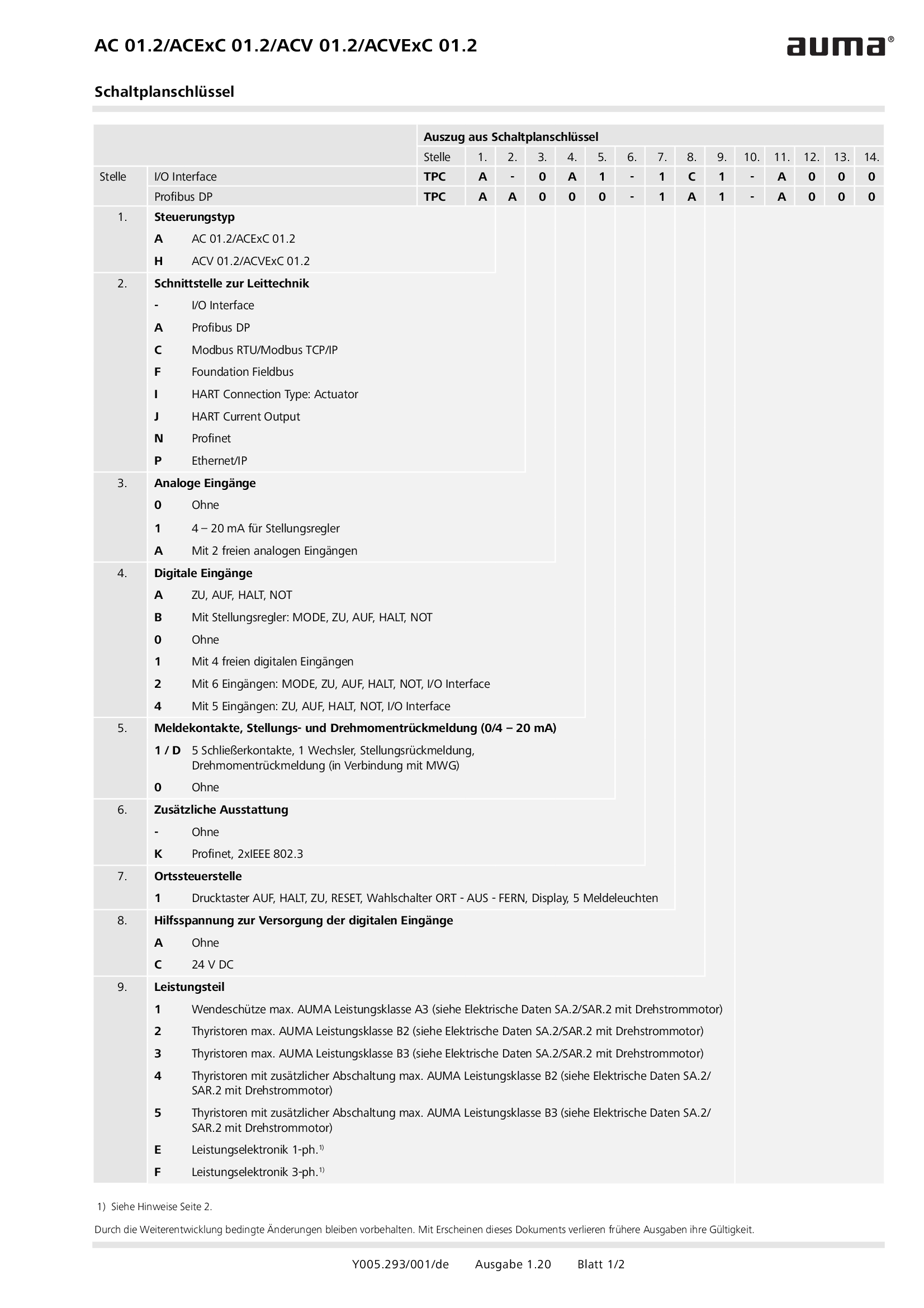
Wiring diagram code for AC 01.2/ACExC 01.2/ACV 01.2/ACVExC 01.2
Wiring diagram
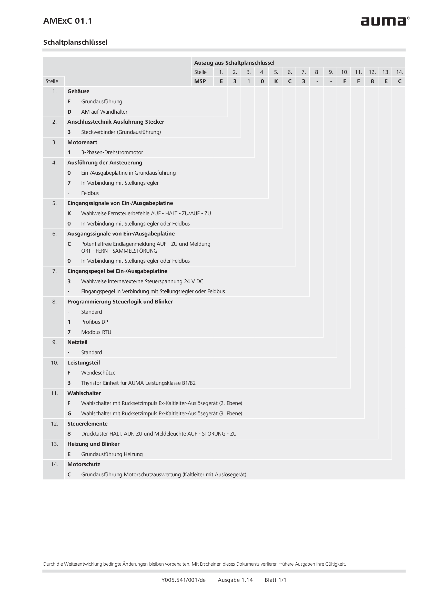
Wiring diagram code for AMExC 01.1
Wiring diagram


