Technical data
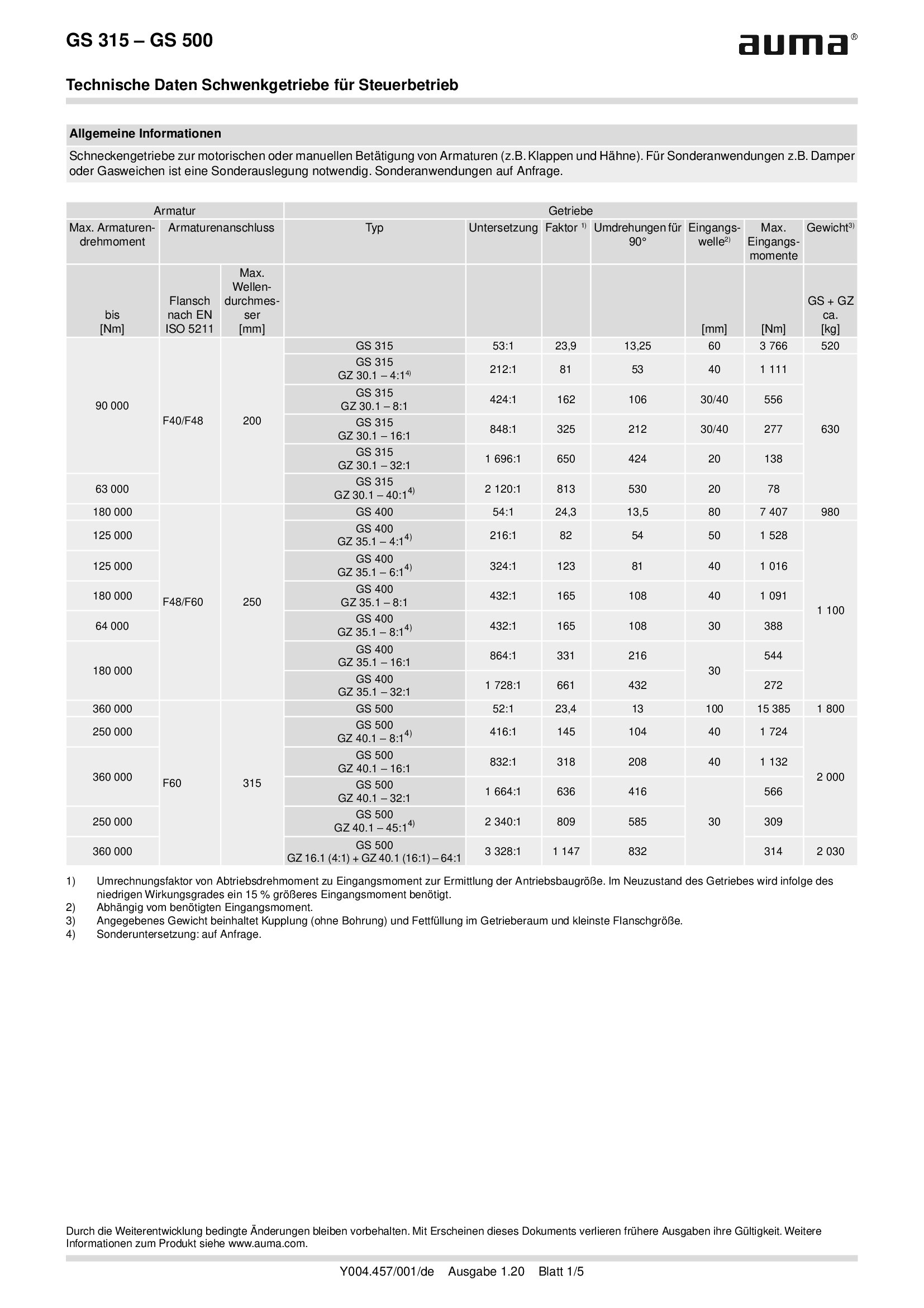
Part-turn gearboxes GS 315 - 500, open-close duty
Technical data
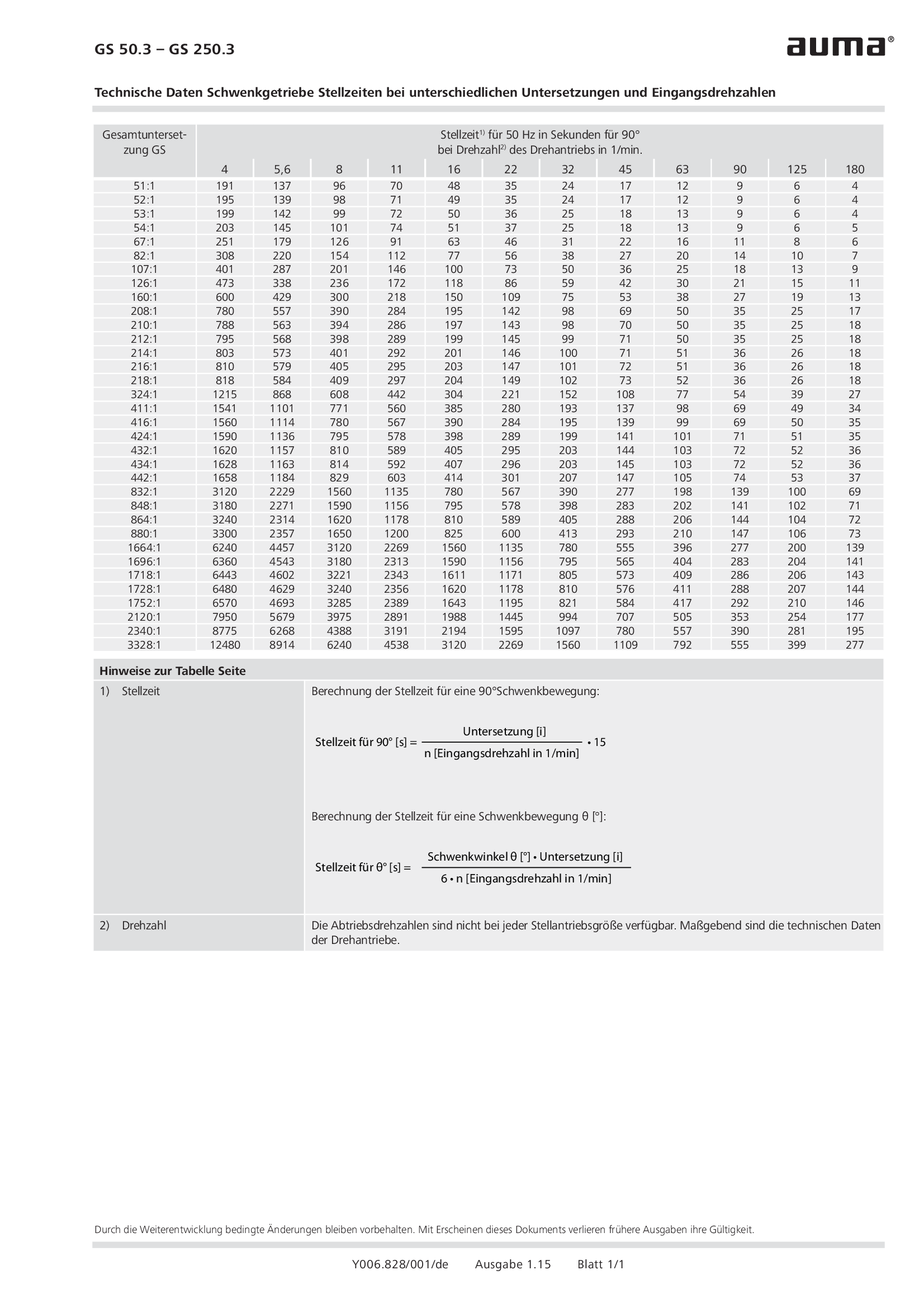
Part-turn gearboxes GS 50.3 - 250.3, Operating times for different reduction ratios and input speeds
Technical data

Part-turn gearboxes GS 50.3 - 250.3, modulating duty
Technical data
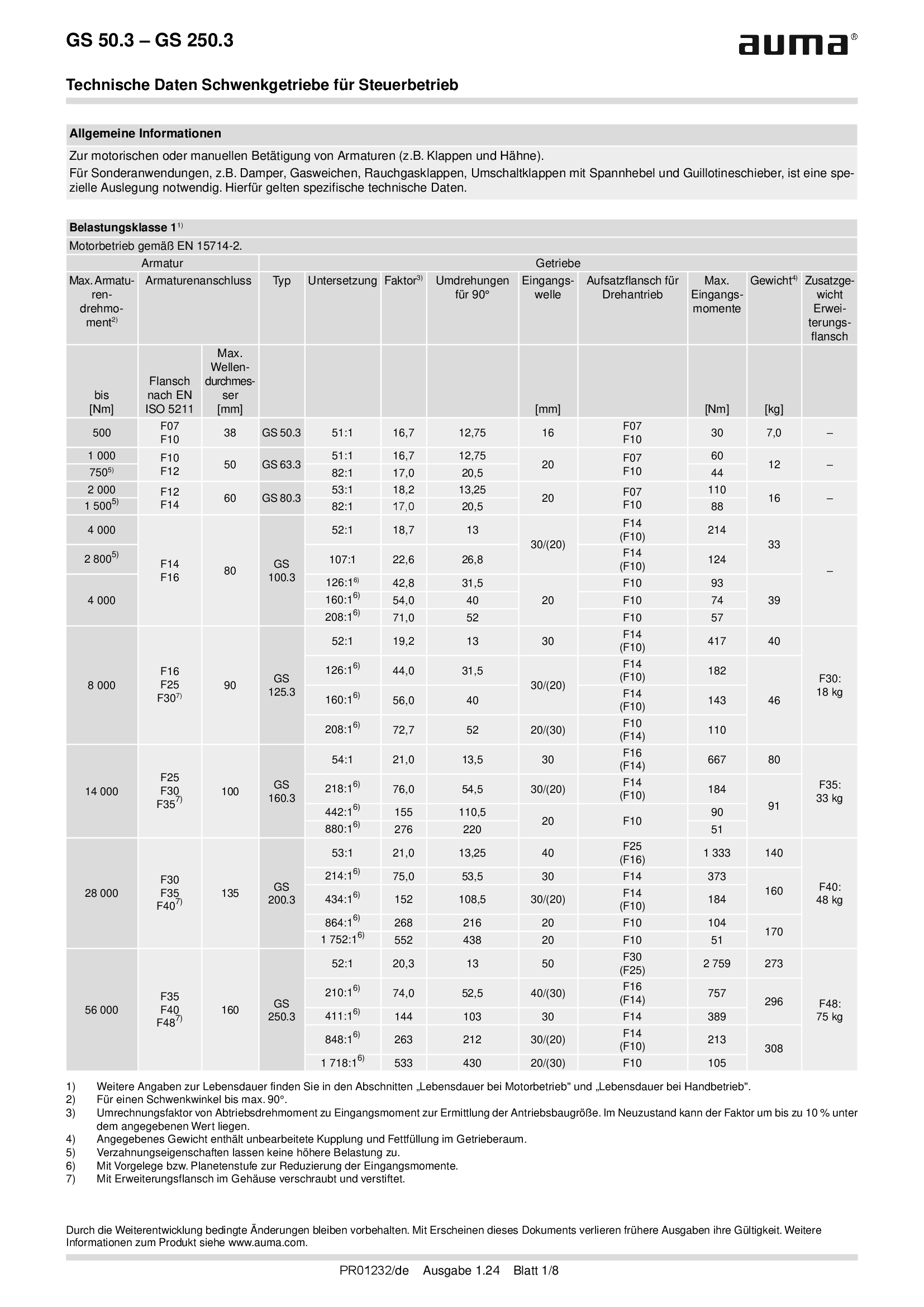
Part-turn gearboxes GS 50.3 - 250.3, open-close duty
Technical data
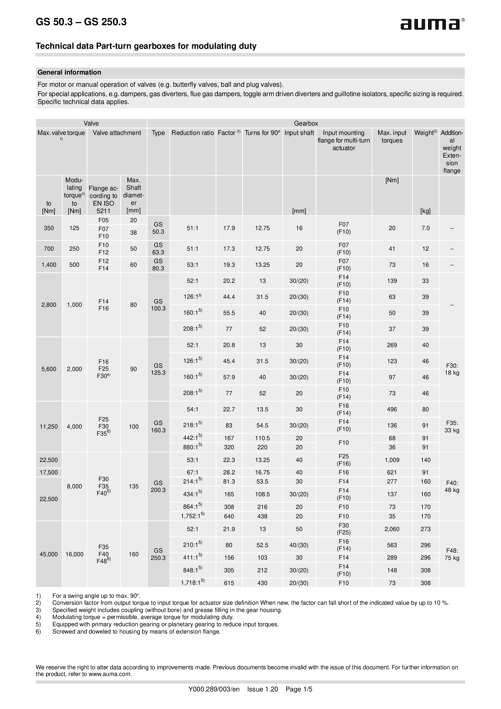
Part-turn gearboxes GS 50.3 - 250.3, modulating duty
Technical data
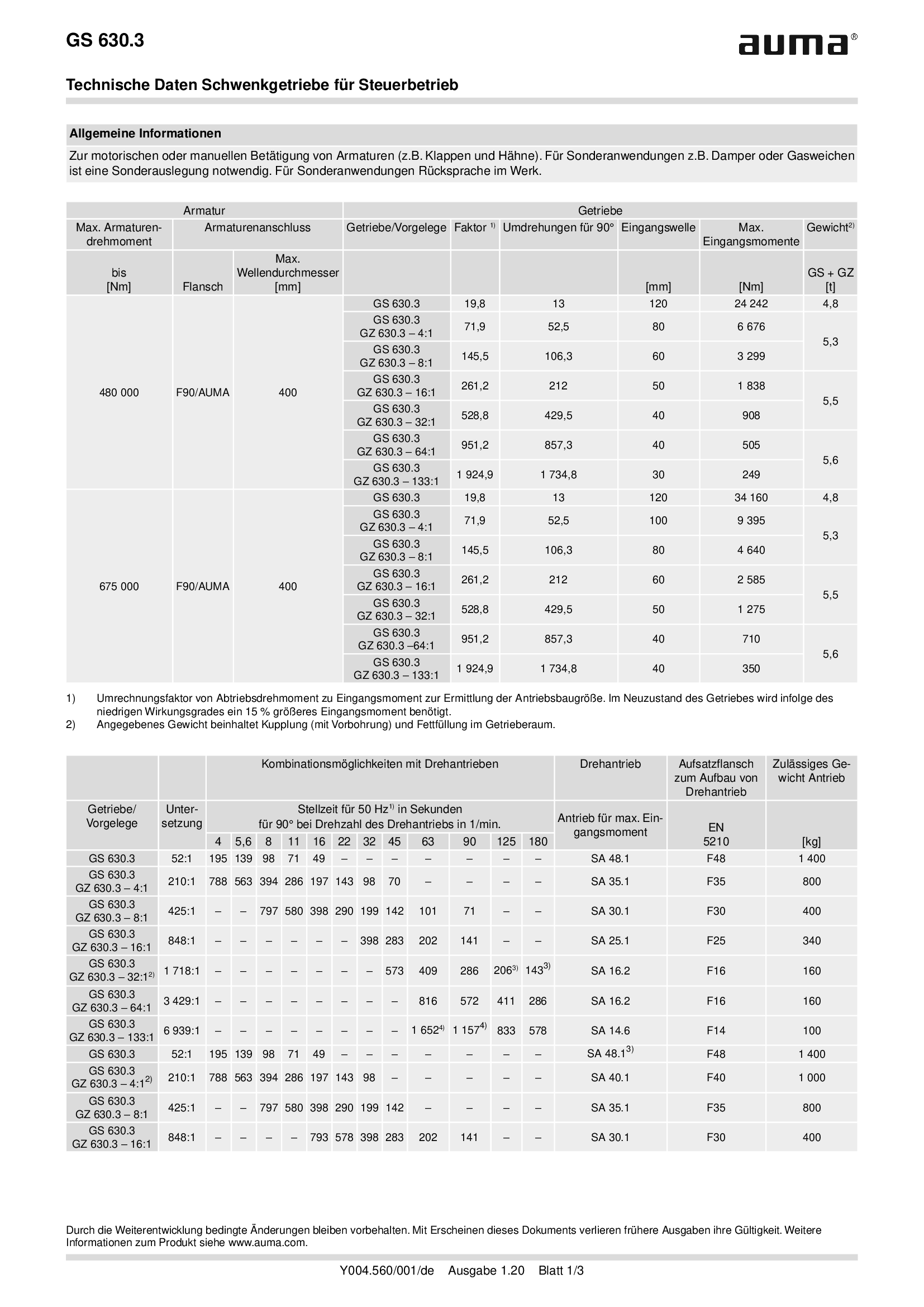
Part-turn gearboxes GS 630.3, GZ 630.3, open-close duty
Technical data
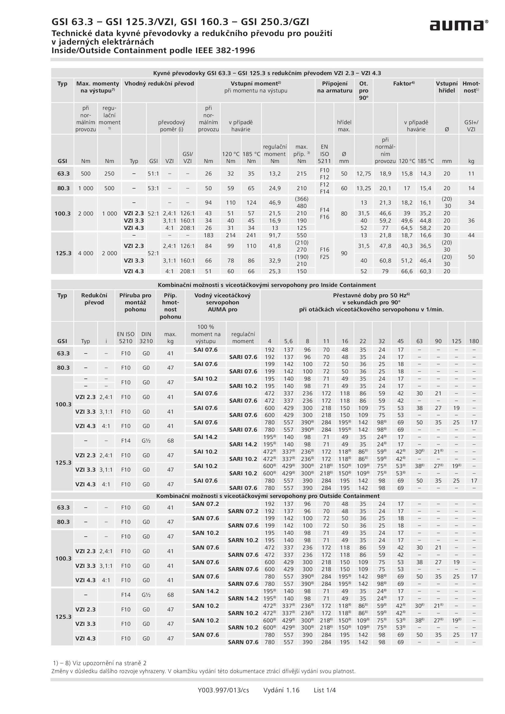
Part-turn gearboxes GSI 63.3 - 250.3, VZI/GZI, nuclear power plants, IEEE 382-1996
Technical data
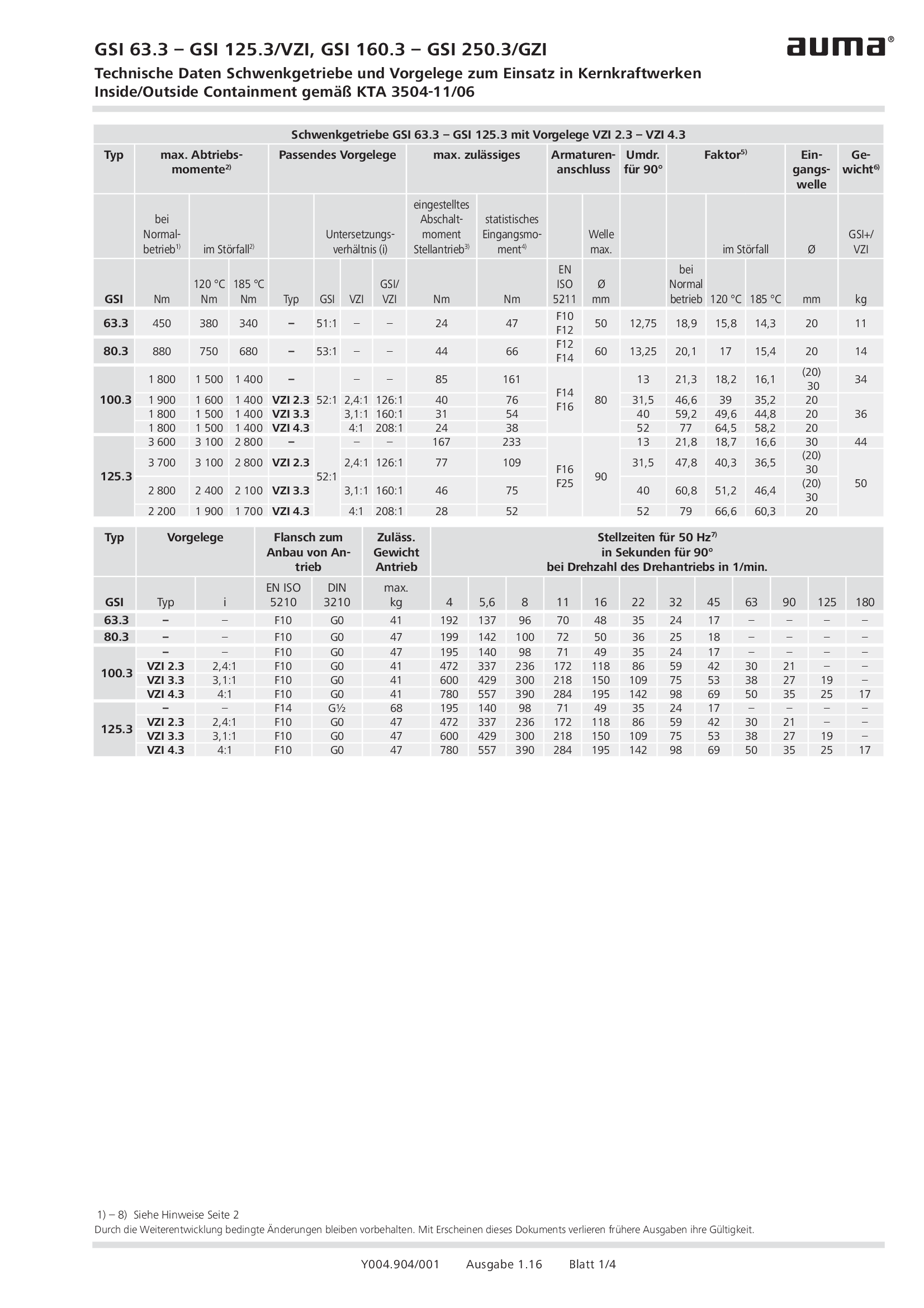
Part-turn gearboxes GSI 63.3 - 250.3, VZI/GZI, nuclear power plants, KTA 3504-11/09
Technical data
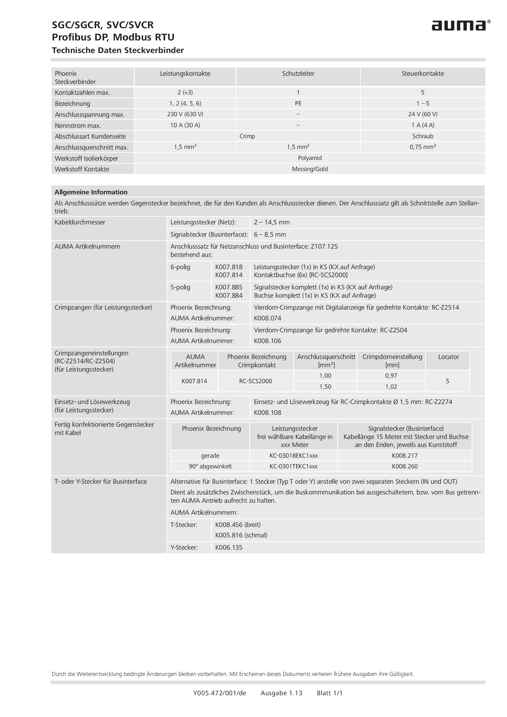
Plug/socket connector, SGC/SGCR, SVC/SVCR, Profibus DP, Modbus RTU
Technical data
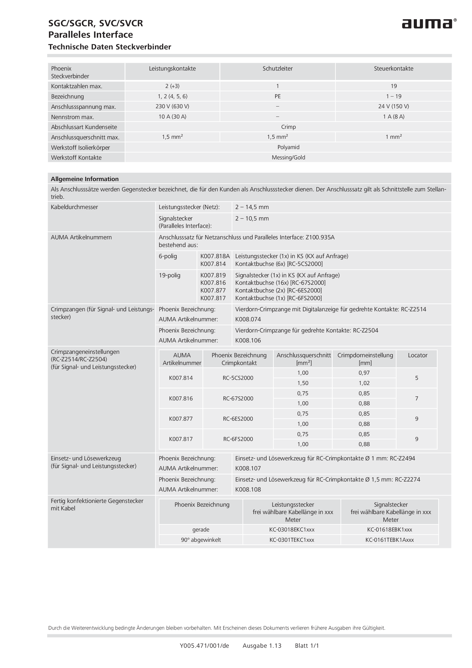
Plug/socket connector, SGC/SGCR, SVC/SVCR, parallel interface
Technical data
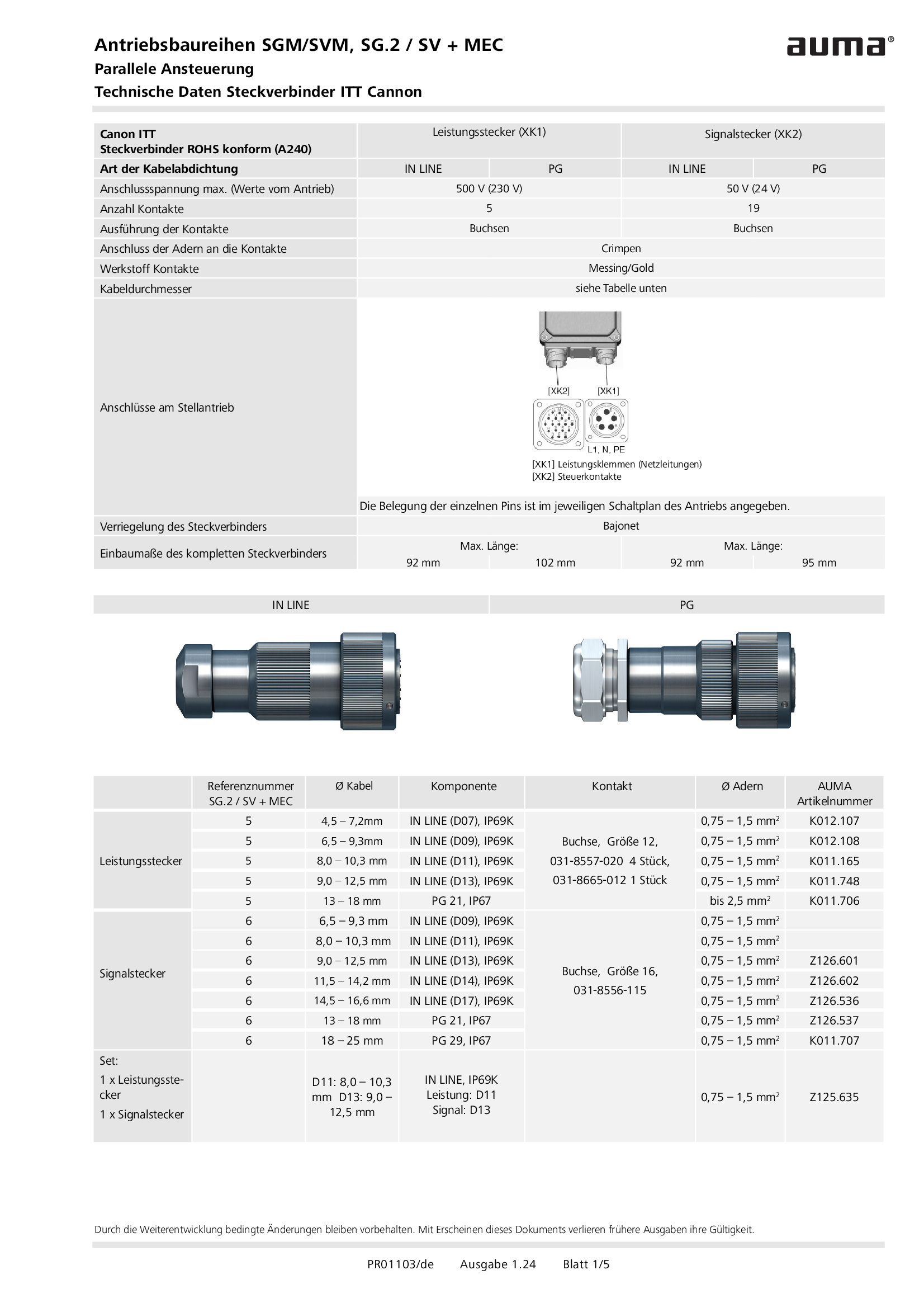
Plug/socket connector, SGM/SVM, Parallel control, ITT Cannon
Technical data
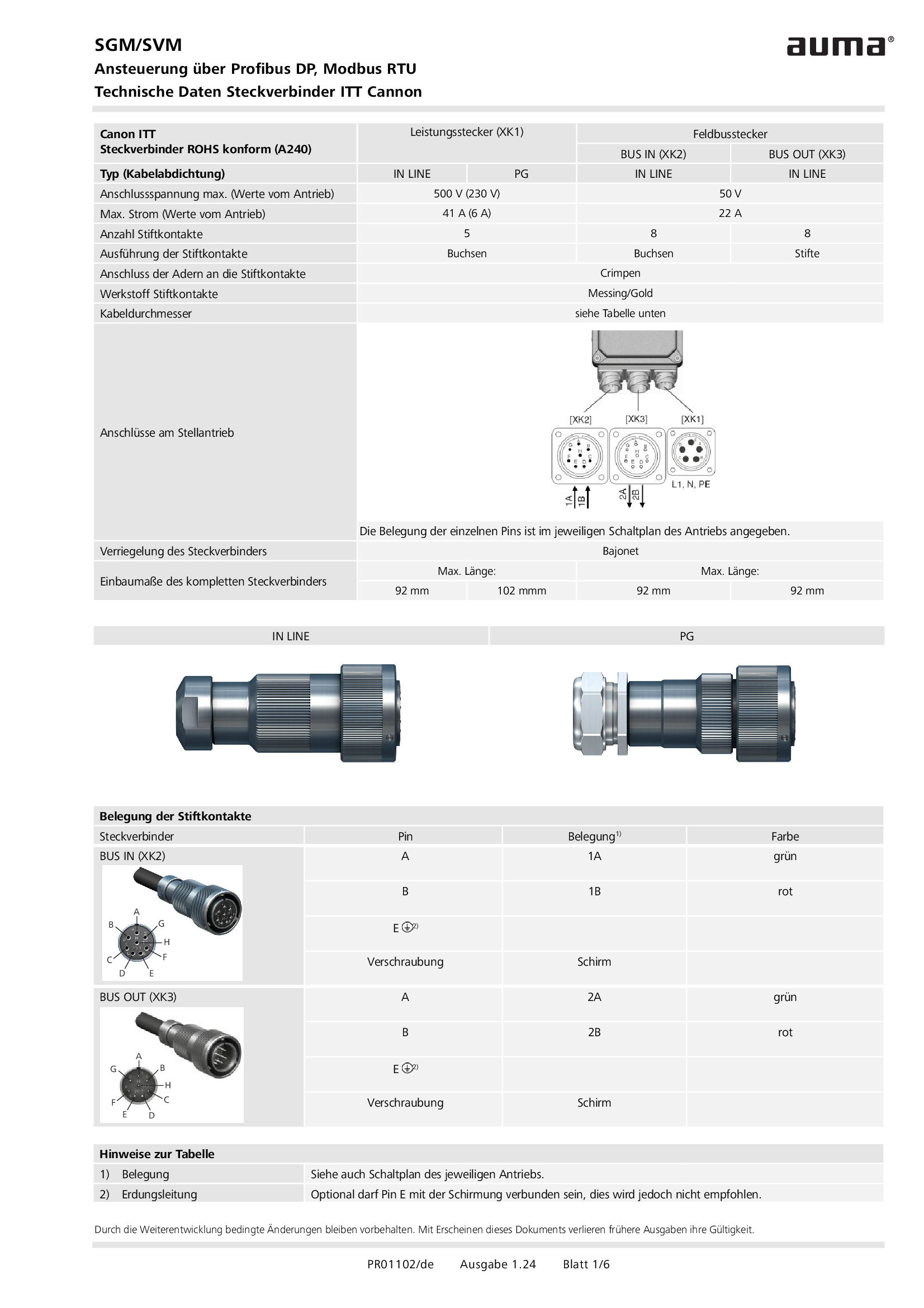
Plug/socket connector, SGM/SVM, Profibus DP, Modbus RTU, ITT Cannon
Technical data
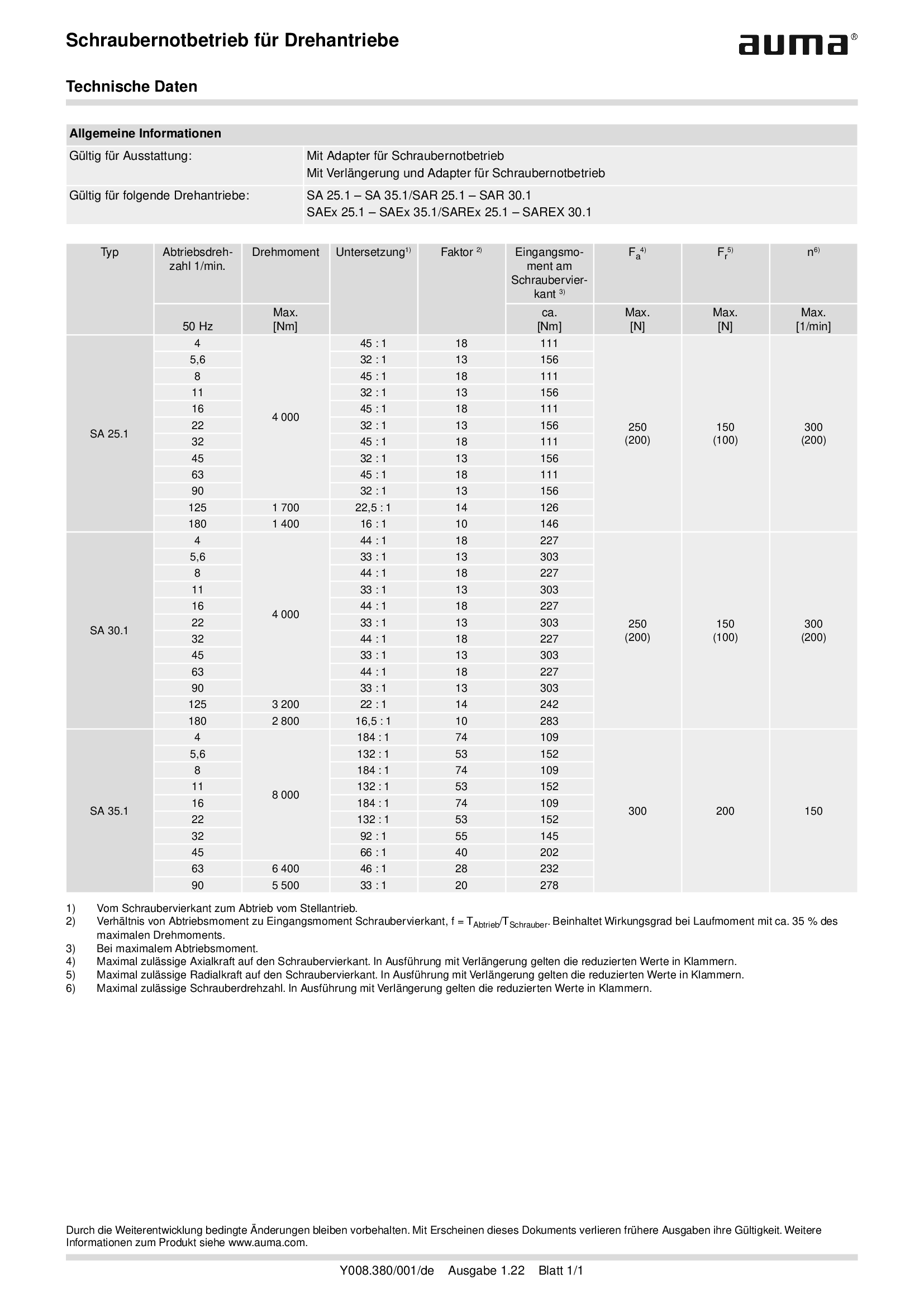
Power tool for emergency operation for multi-turn actuators SA .1
Technical data
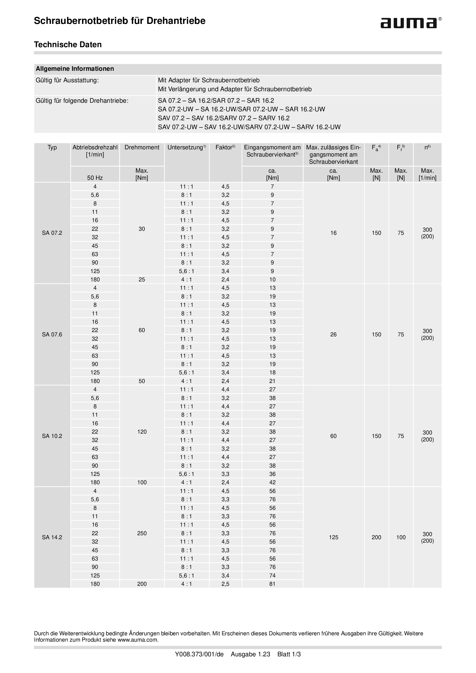
Power tool for emergency operation for multi-turn actuators SA .2
Technical data
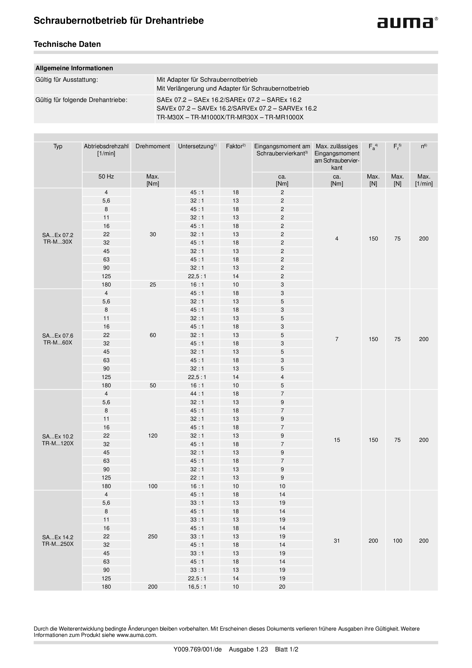
Power tool for emergency operation for multi-turn actuators SAEx .2 and TIGRON
Technical data
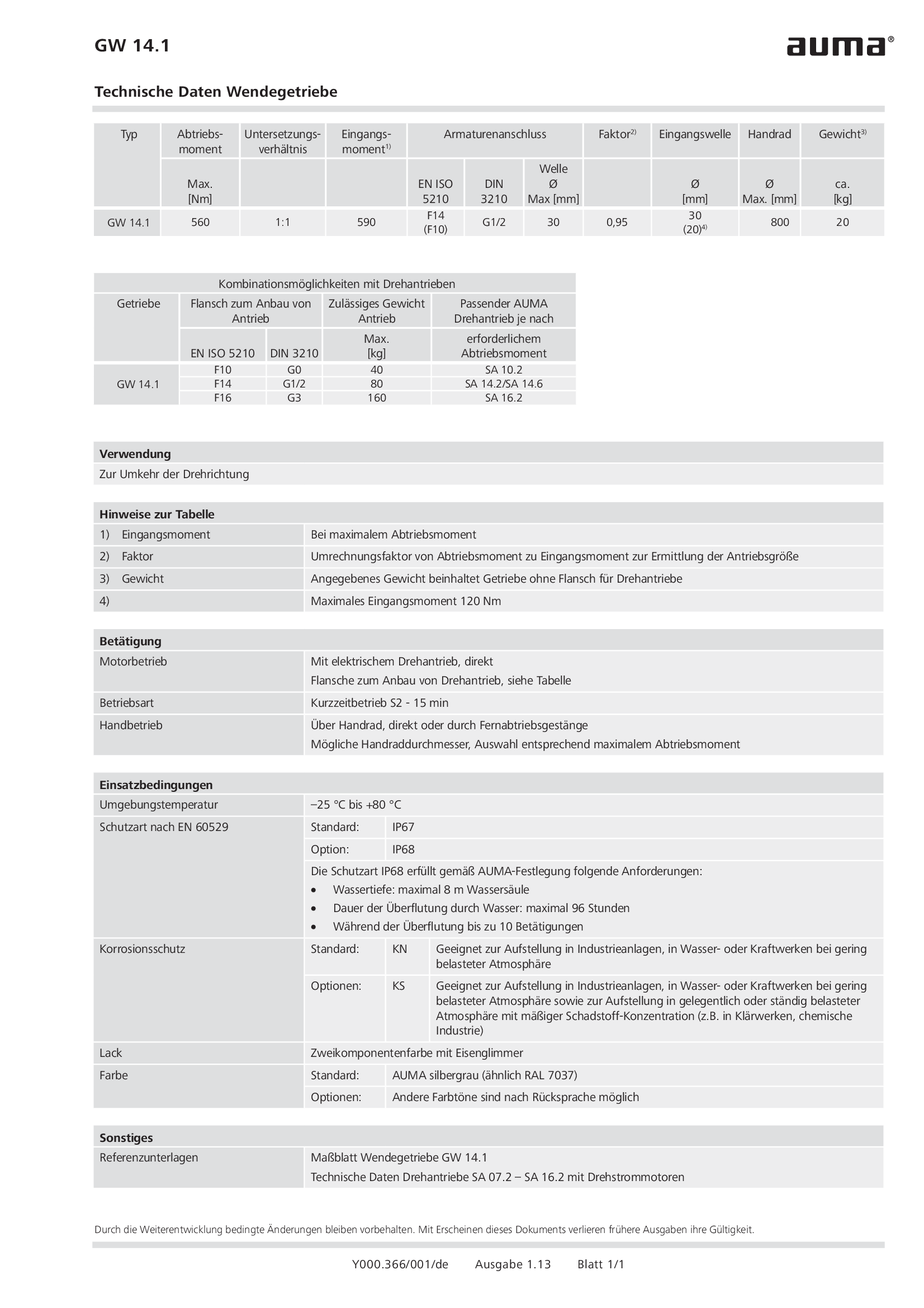
Reversing gearbox GW 14.1
Technical data
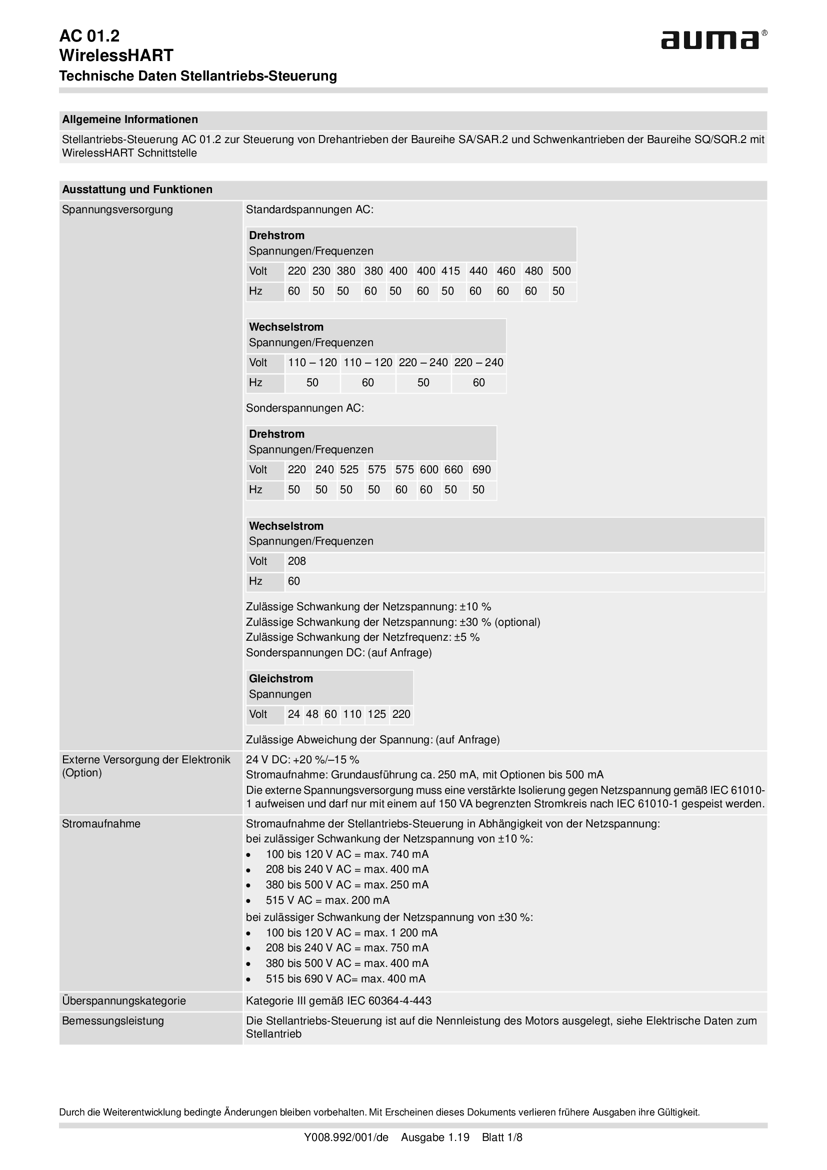
Stellantriebs-Steuerung AUMATIC AC 01.2, WirelessHART
Technical data
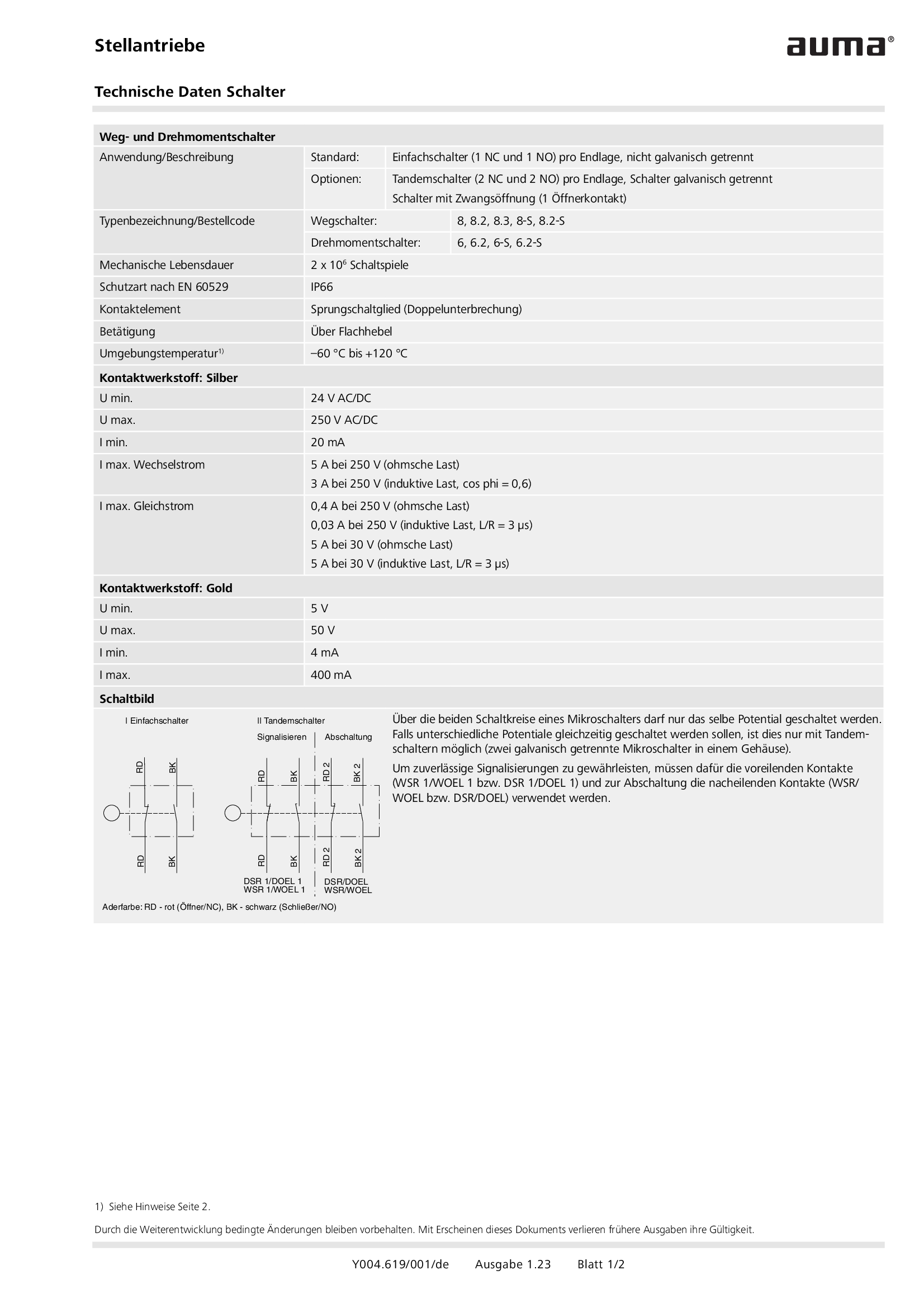
Switches for actuators
Technical data
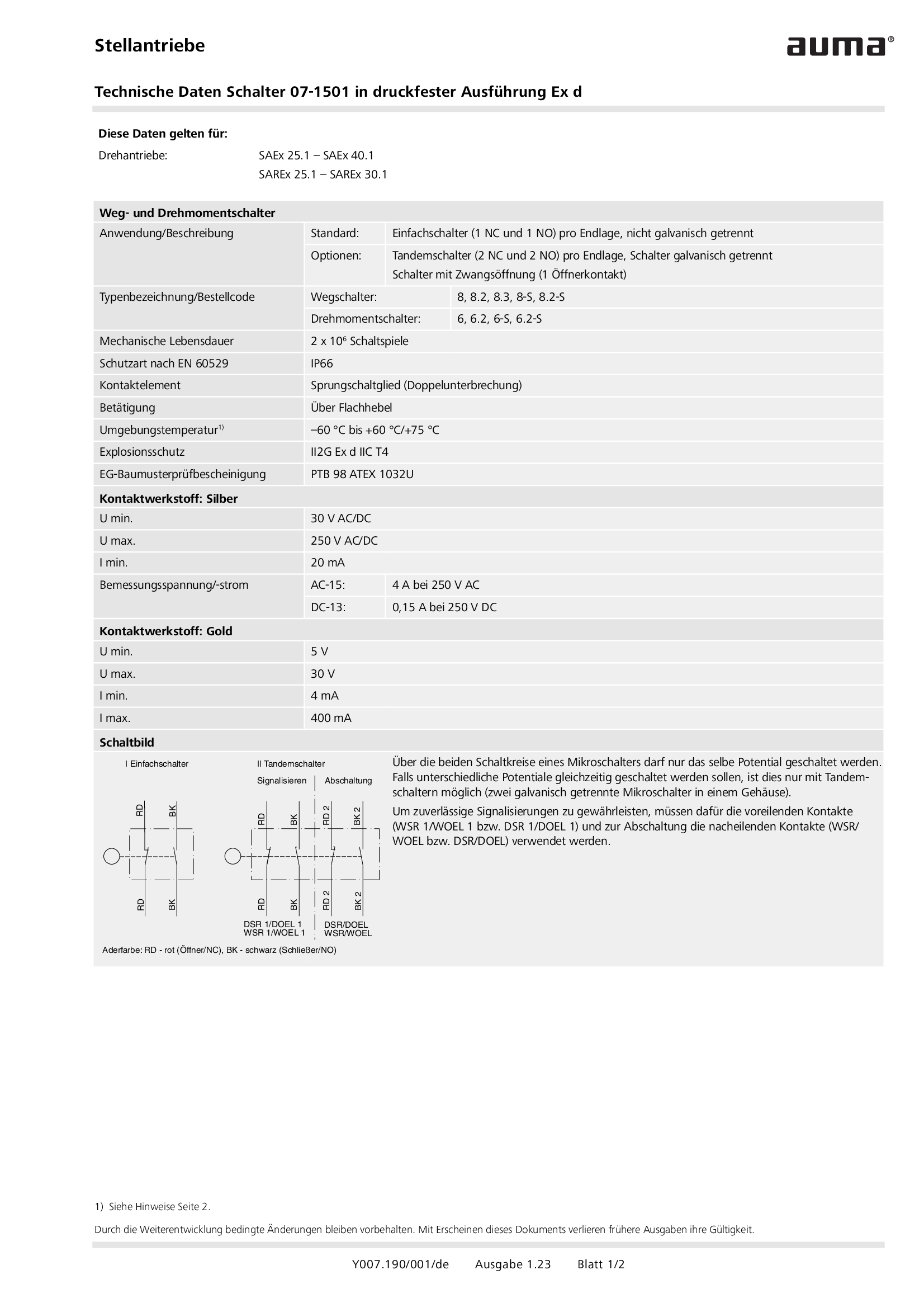
Switches in flameproof enclosure for actuators
Technical data
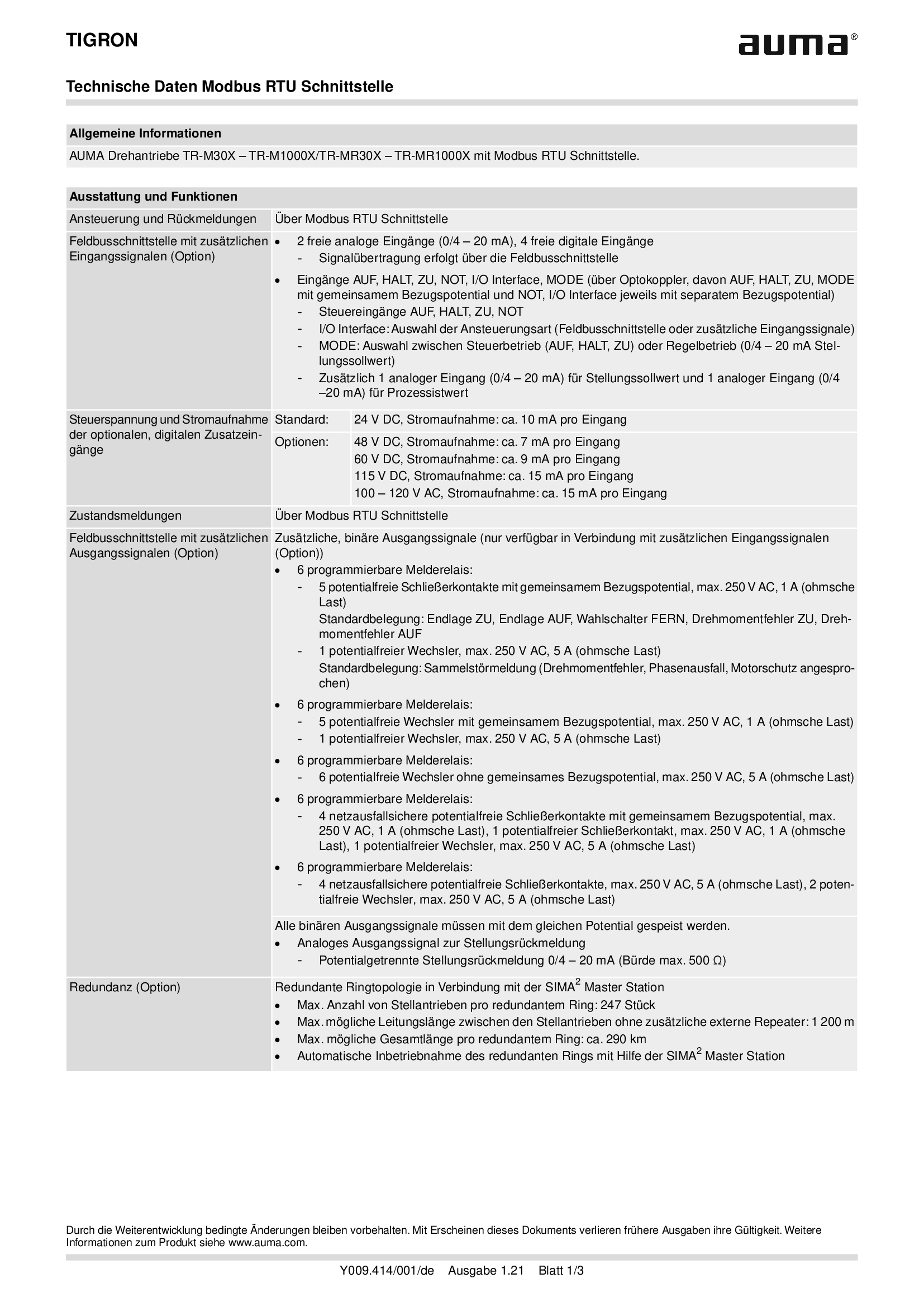
TIGRON, Modbus RTU Schnittstelle
Technical data

TIGRON, Profibus DP interface
Technical data
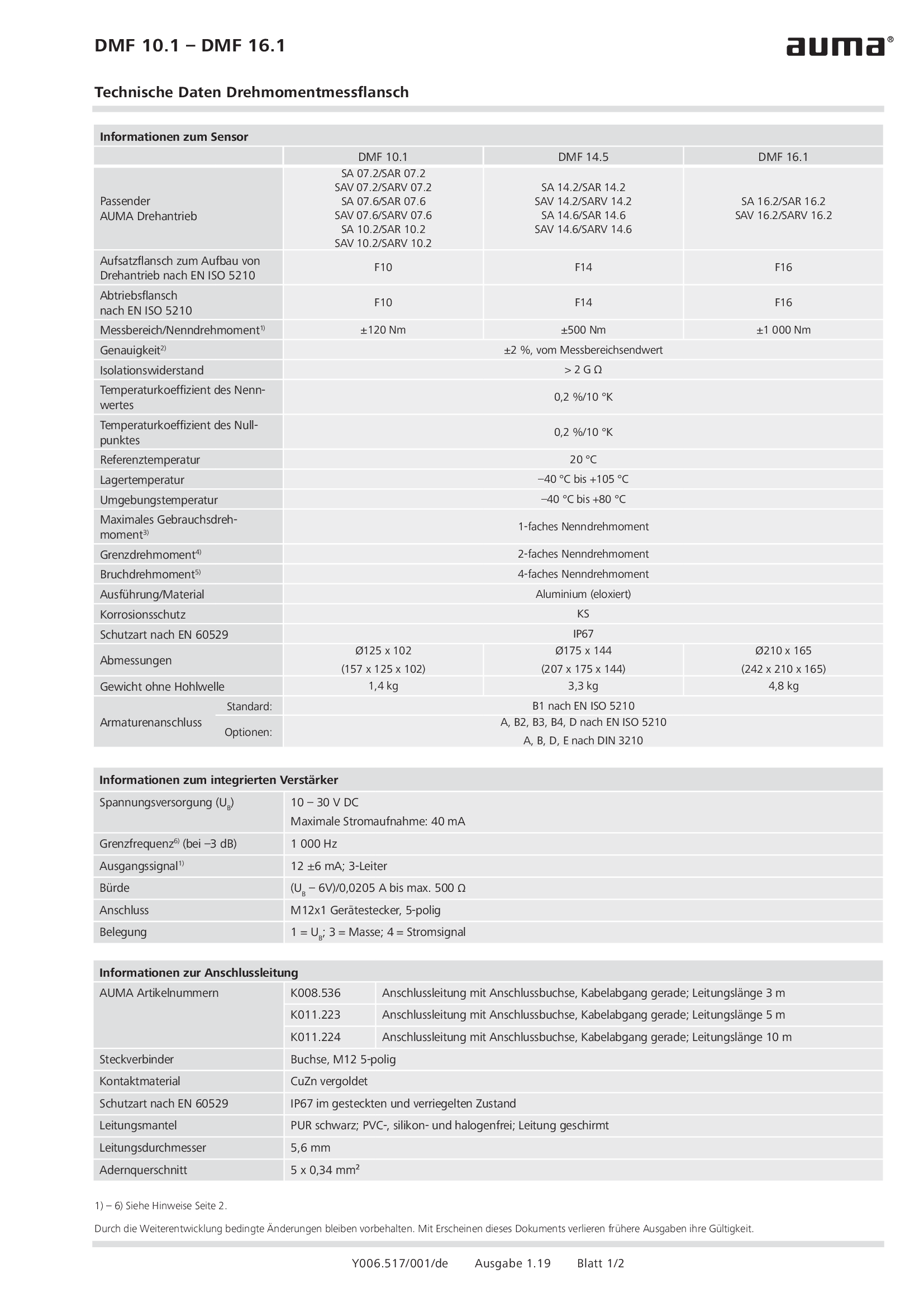
Torque measurement flange DMF 10.1 - 16.1
Technical data

Valve actuators SV 05.1 - 07.1 MEC 02.1
Technical data
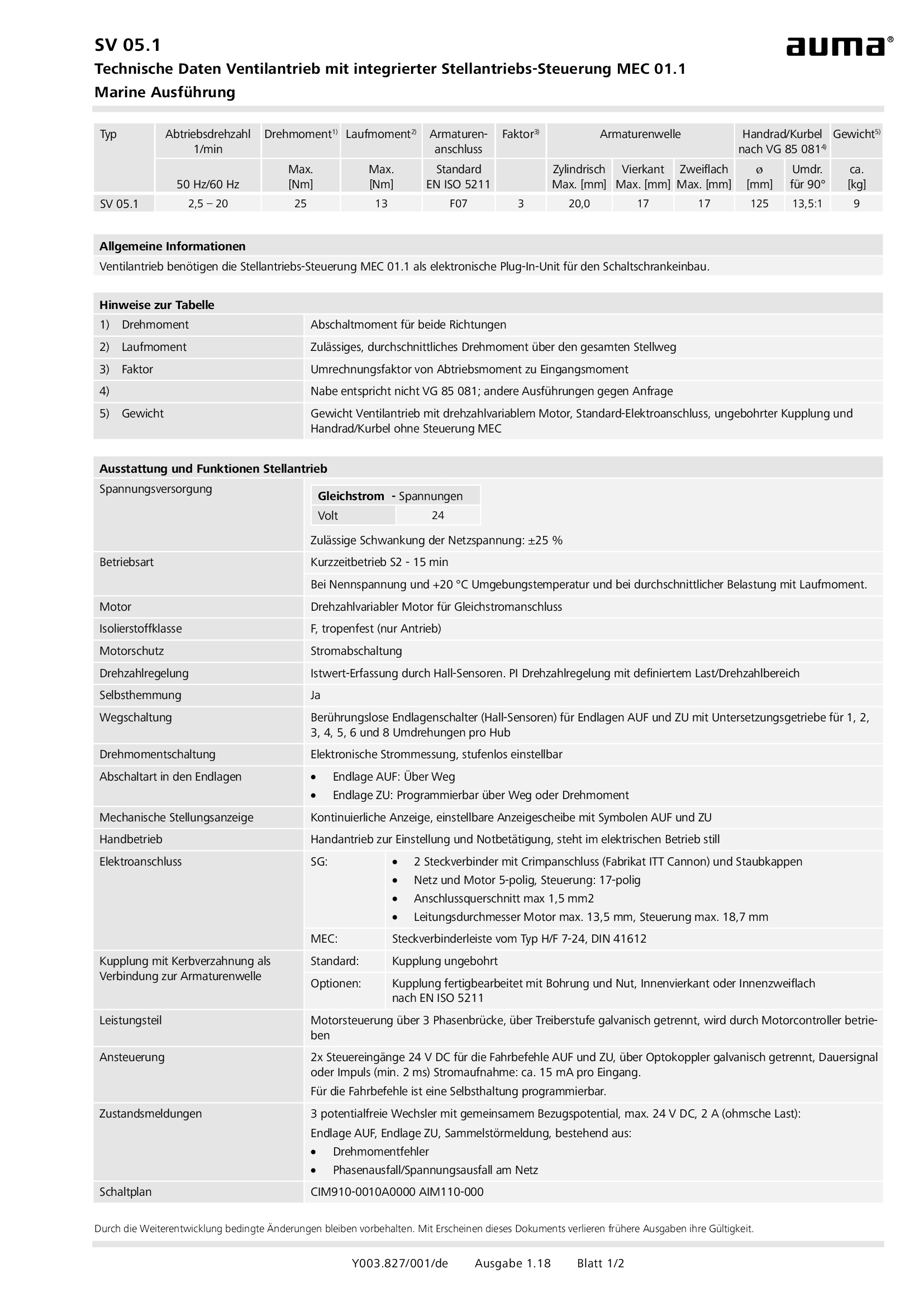
Valve actuators SV 05.1 - 07.1 MEC 02.1, military ship building (navy)
Technical data

Valve actuators SV 05.1 - 07.1 MEC 03.1
Technical data

Valve actuators SVC/SVCR 05.1 - 07.5
Technical data

Valve actuators SVC/SVCR 05.1 - 07.5, Modbus RTU
Technical data

Valve actuators SVC/SVCR 05.1 - 07.5, Profibus DP
Technical data
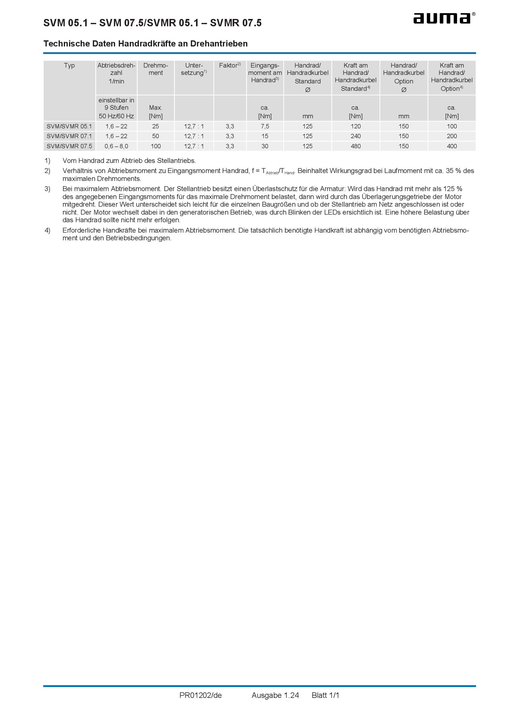
Valve actuators SVM/SVMR 05.1 - 07.5, Handwheel forces
Technical data
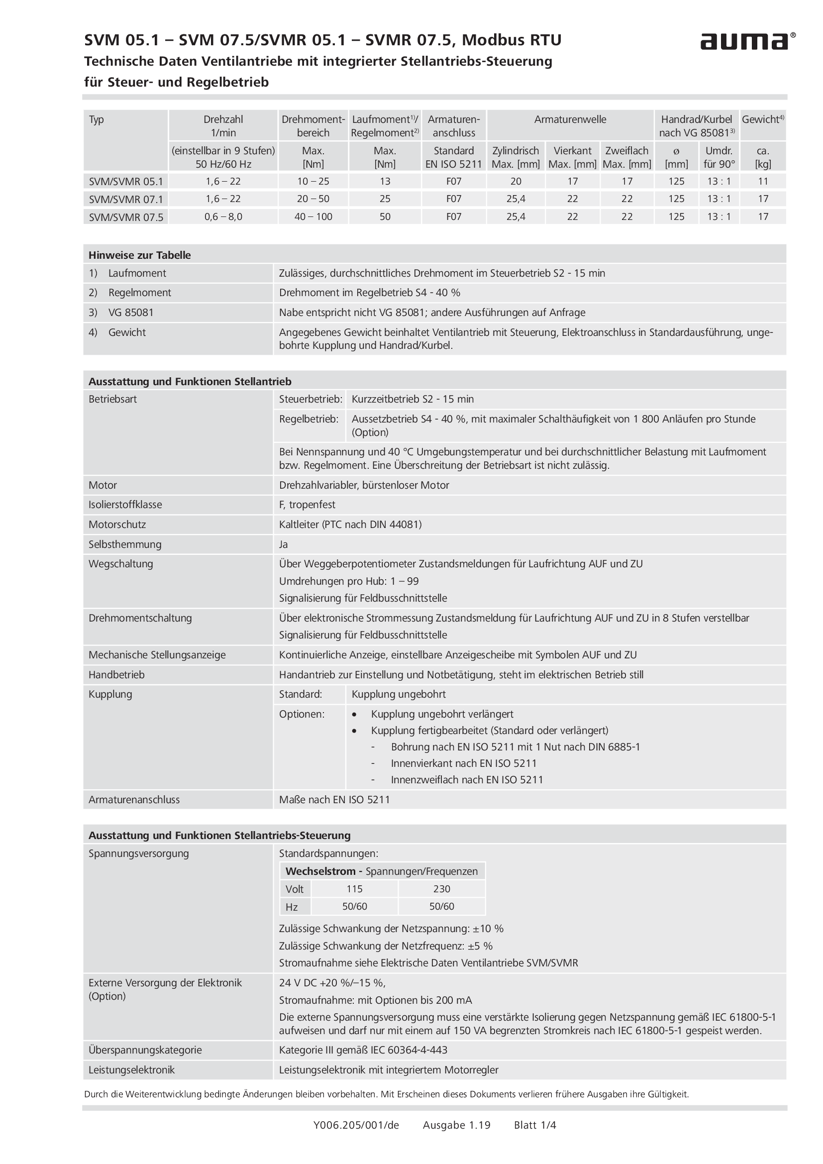
Valve actuators SVM/SVMR 05.1 - 07.5, Modbus RTU, military ship building (navy)
Technical data

Valve actuators SVM/SVMR 05.1 - 07.5, Profibus DP, military ship building (navy)
Technical data
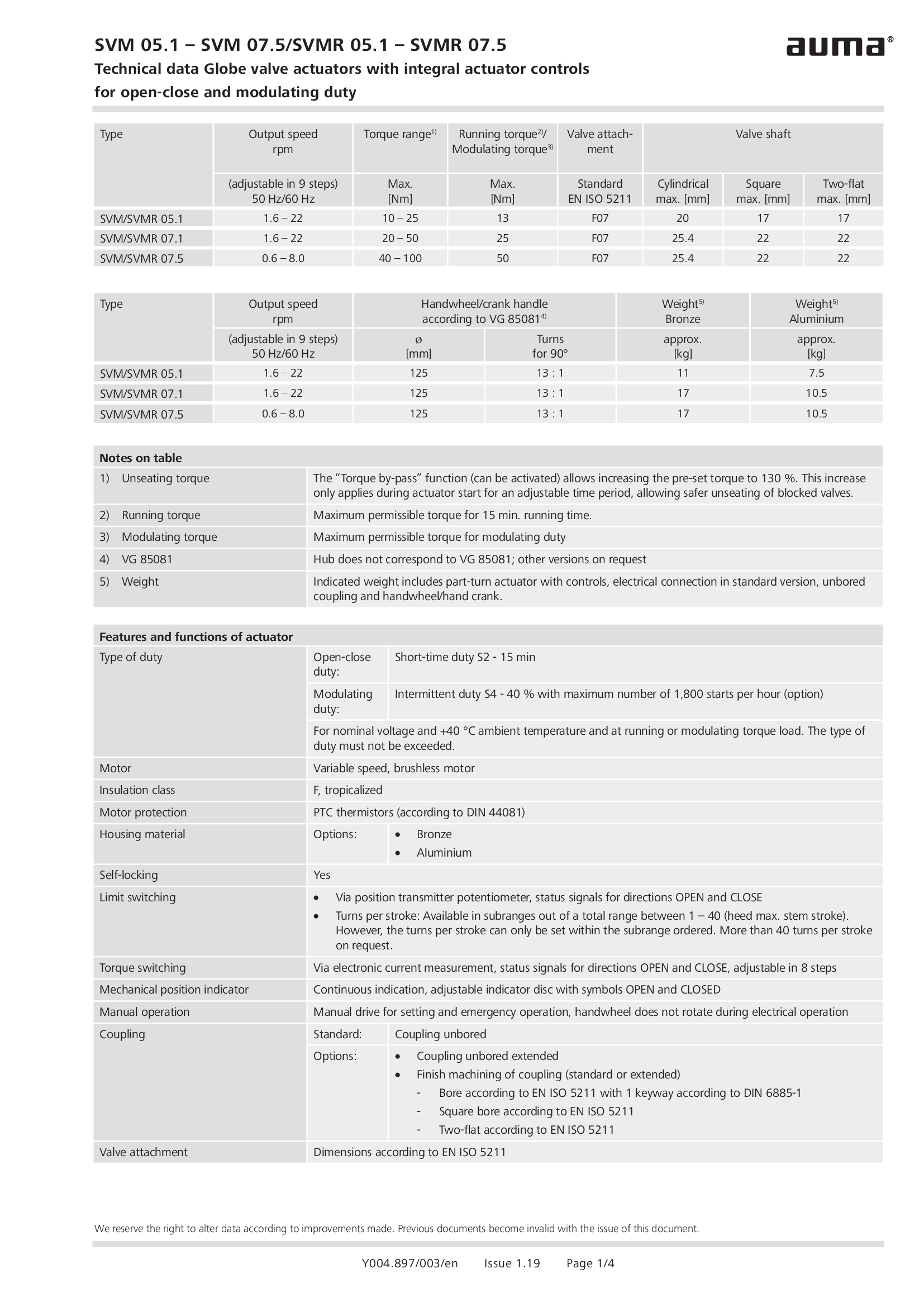
Valve actuators SVM/SVMR 05.1 - 07.5, military ship building (navy)
Technical data
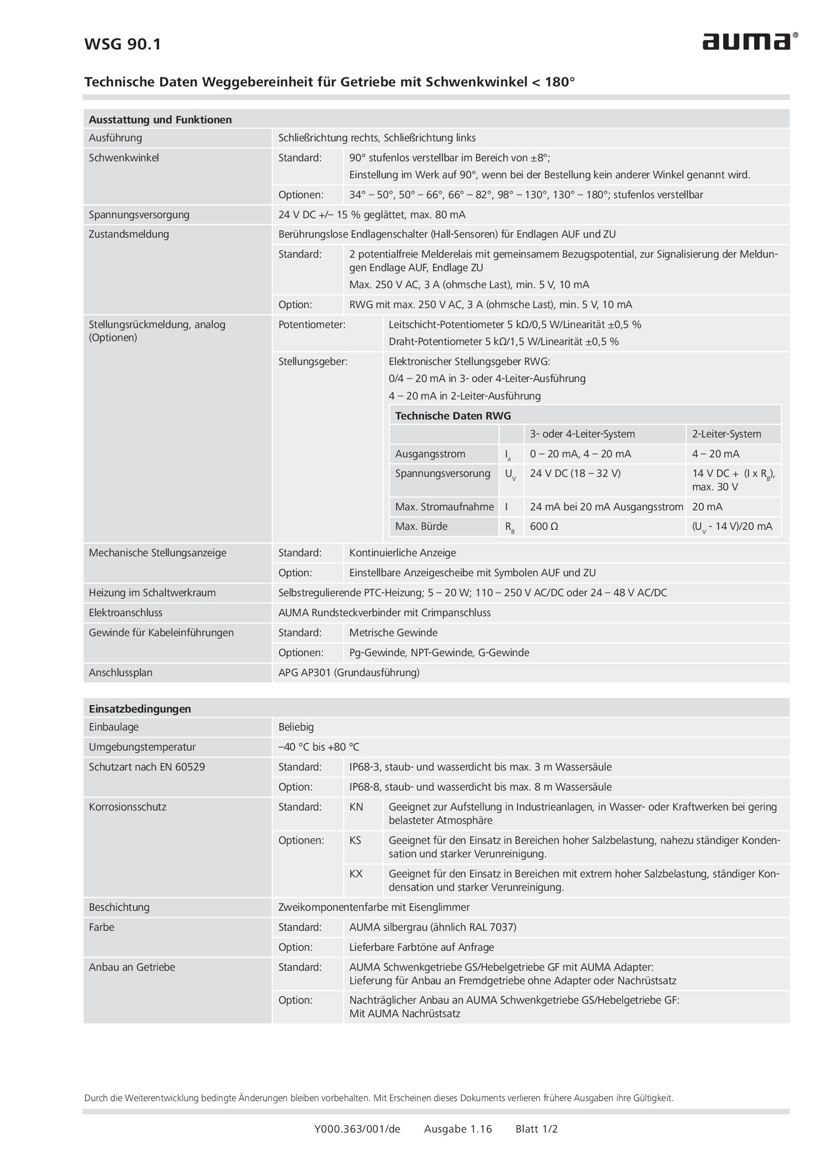
Valve position indicator WSG 90.1
Technical data
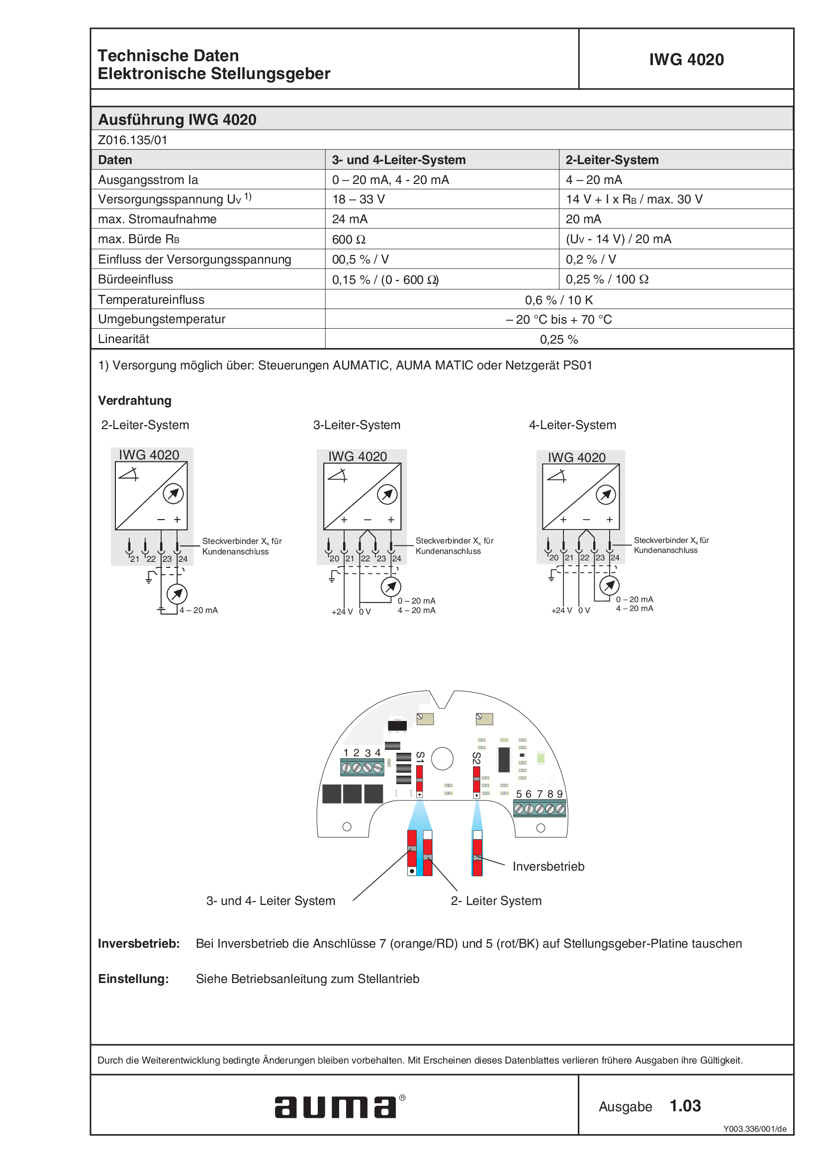
electronic position transmitter IWG 4020
Technical data

spring loaded stem nut output drive AF 10.2 - 60.2
Technical data
Technical description
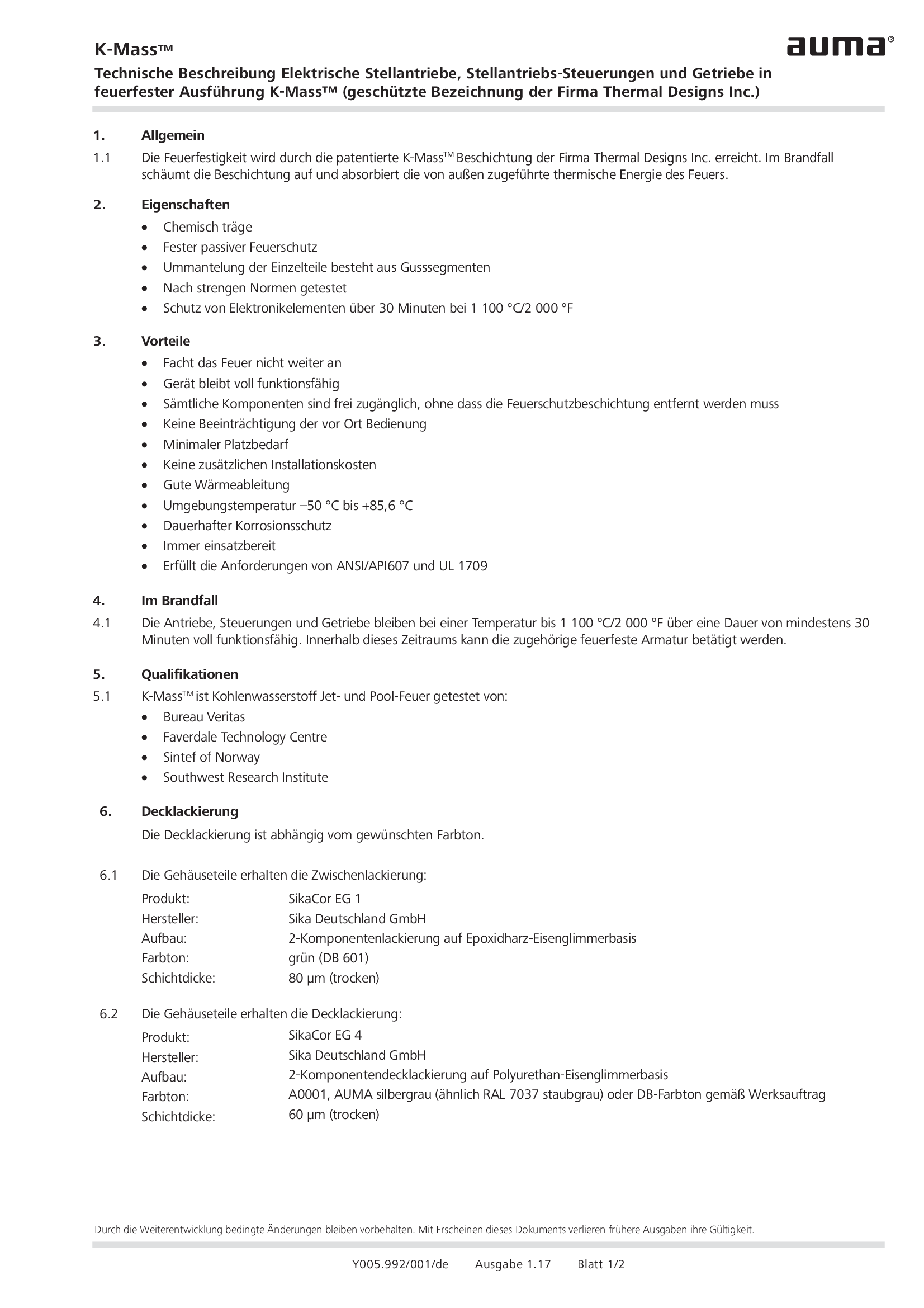
Coating for actuators, actuator controls and gearboxes in fireproof version K-Mass
Technical description
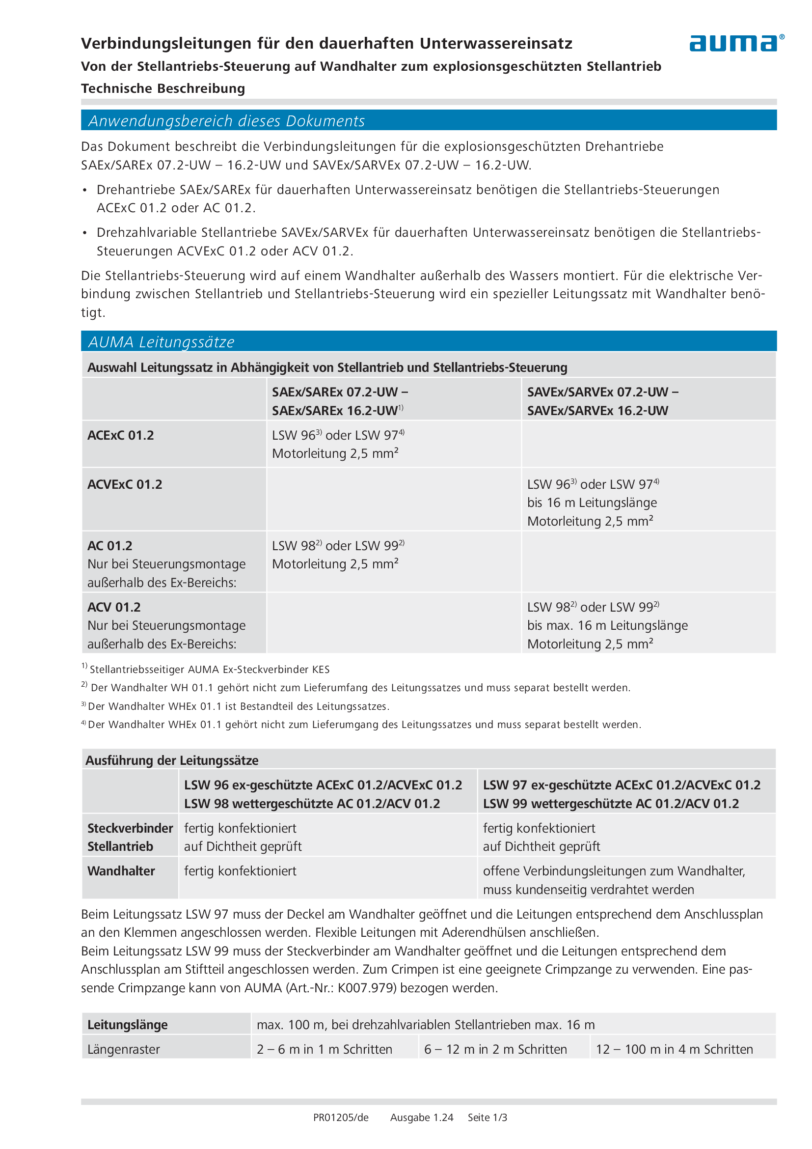
Connecting cable for continuous underwater use (explosion-proof actuator)
Technical description
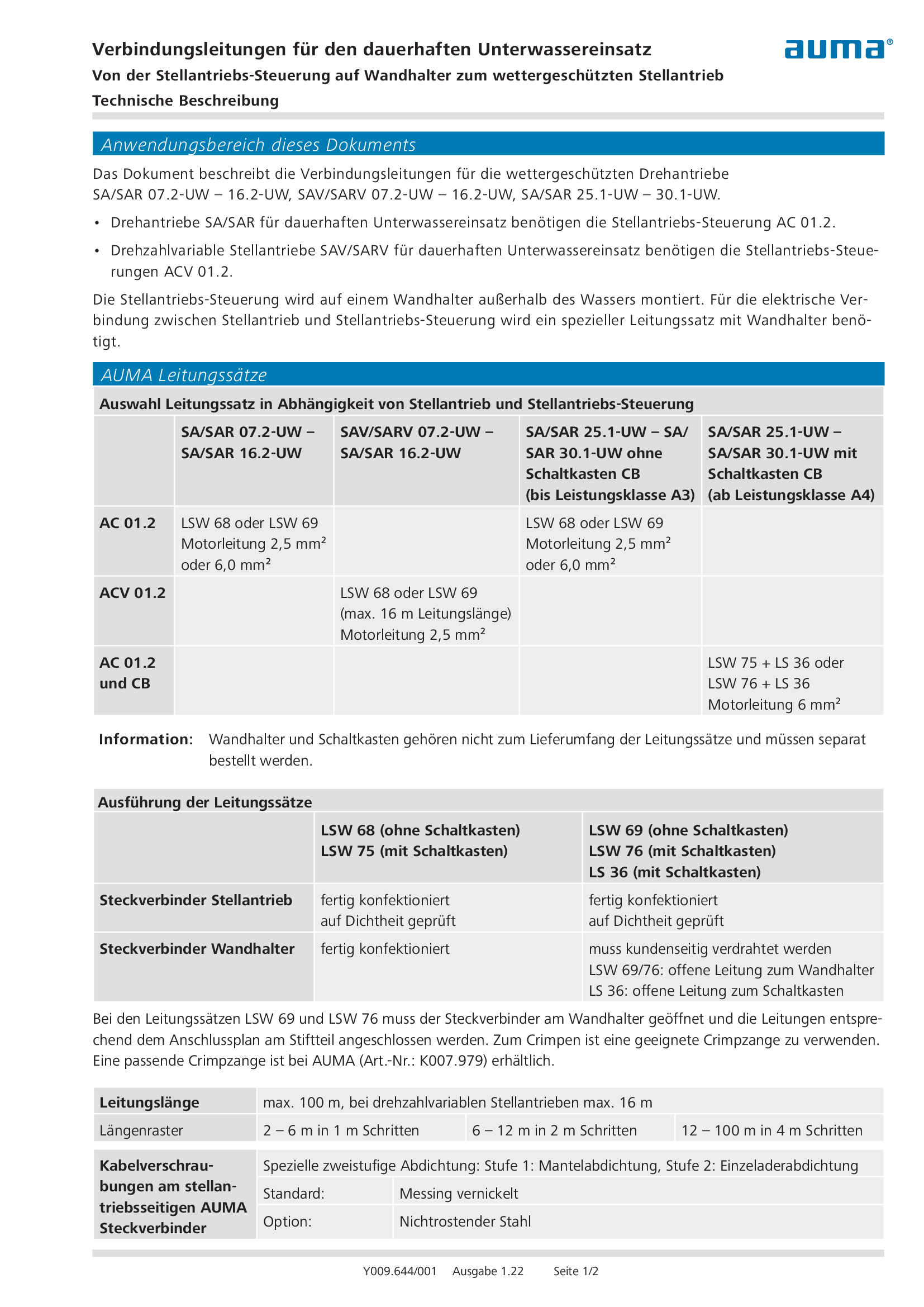
Connecting cable for continuous underwater use (weatherproof actuator)
Technical description
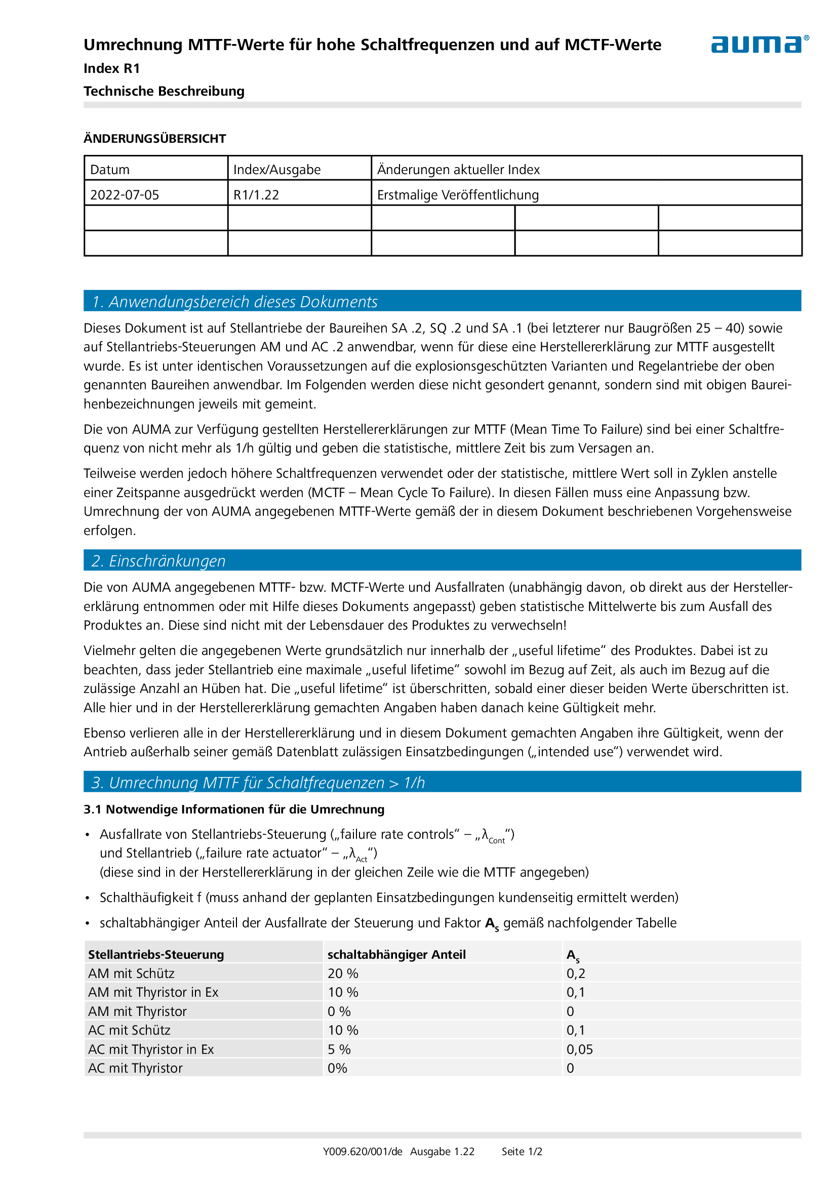
Conversion of MTTF values for high numbers of starts and to MCTF values
Technical description
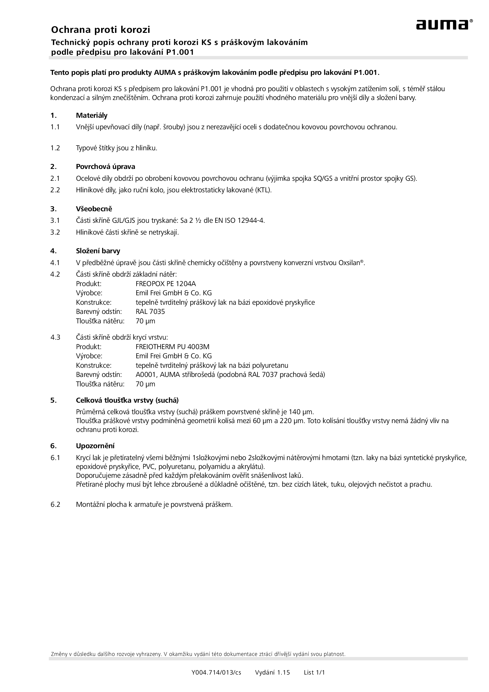
Corrosion protection KS with LV P1.001
Technical description

Corrosion protection KS with LV P1.002
Technical description
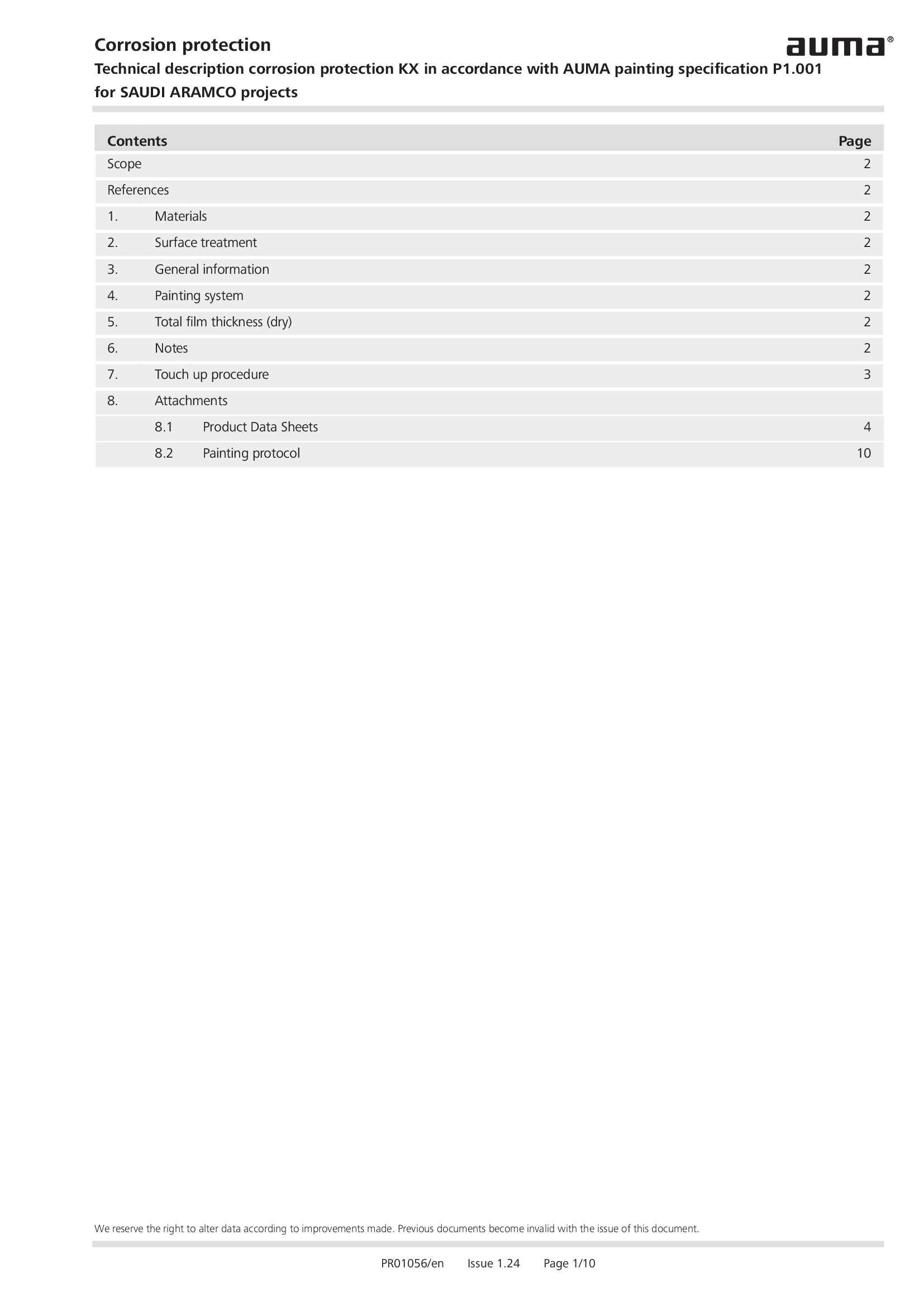
Corrosion protection KX according LV P1.001 for SAUDI ARAMCO Projects
Technical description
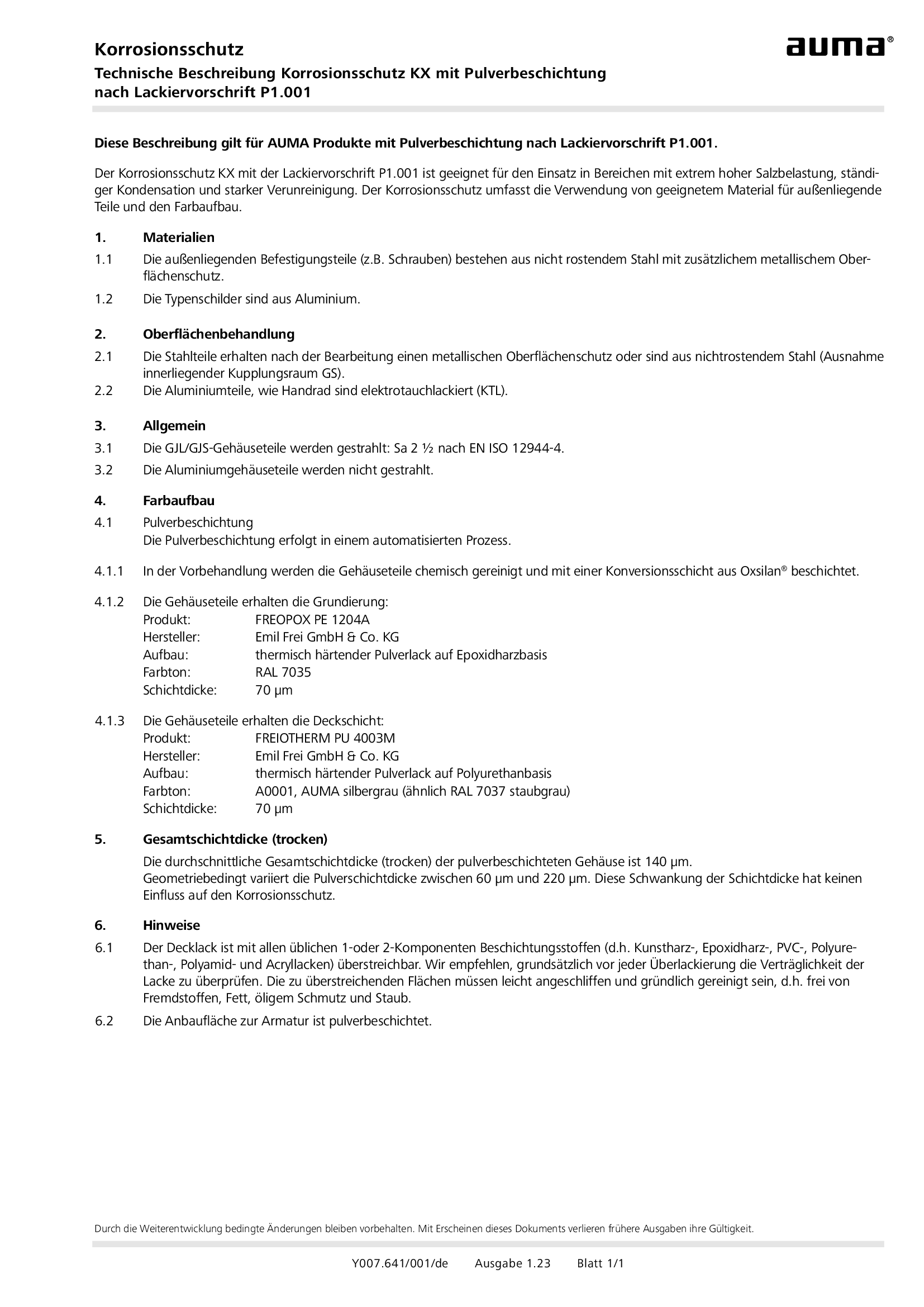
Corrosion protection KX with LV P1.001
Technical description
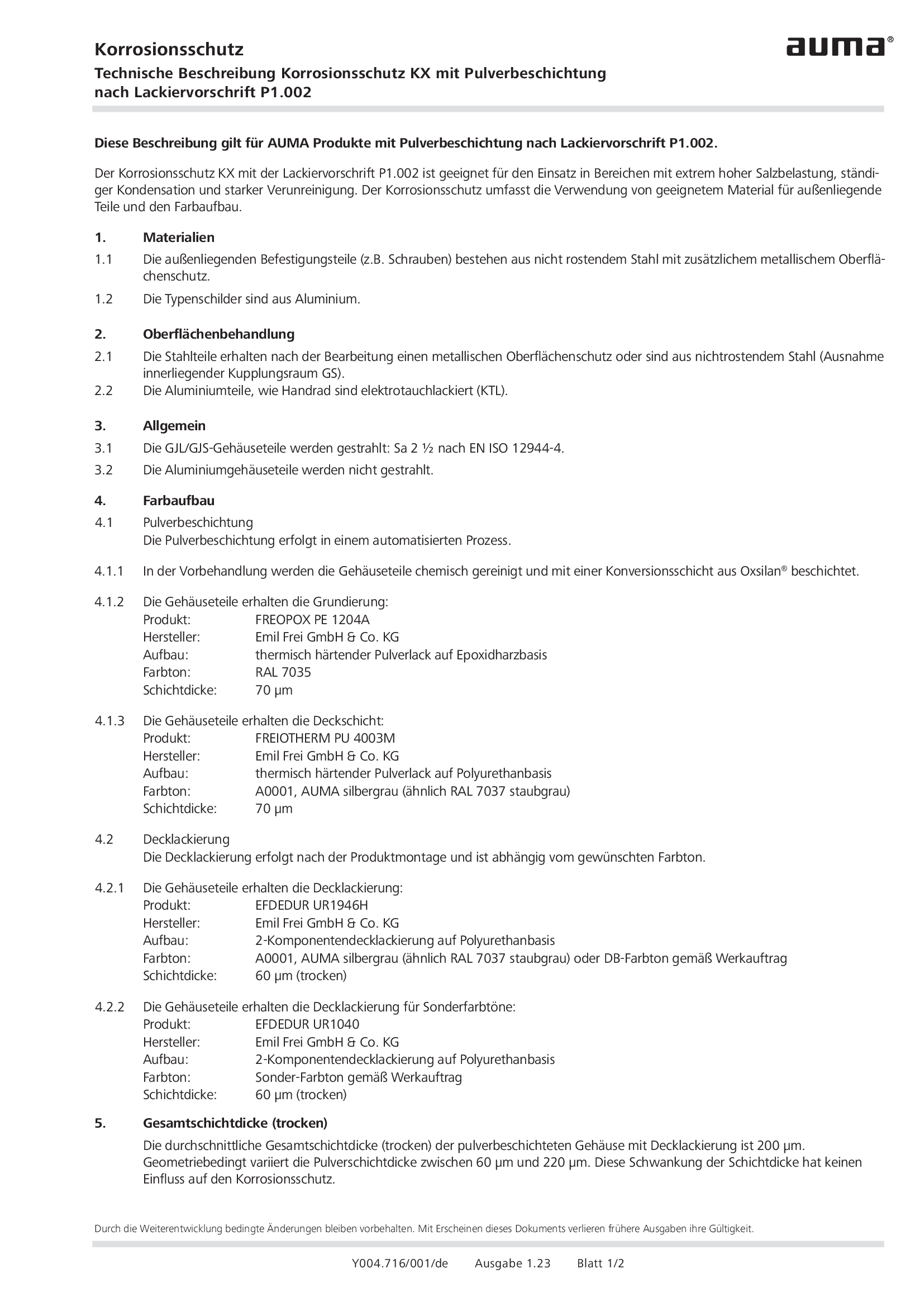
Corrosion protection KX with LV P1.002
Technical description
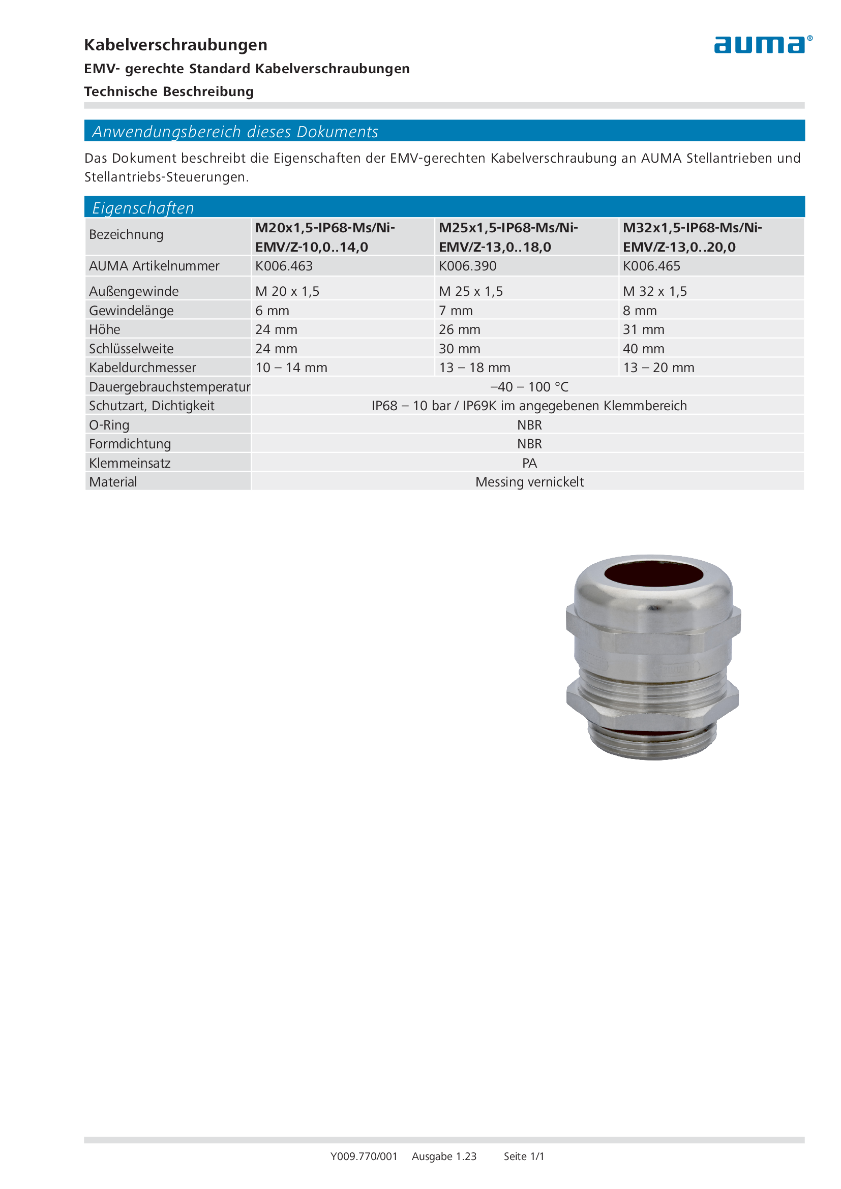
EMC approved standard cable glands
Technical description
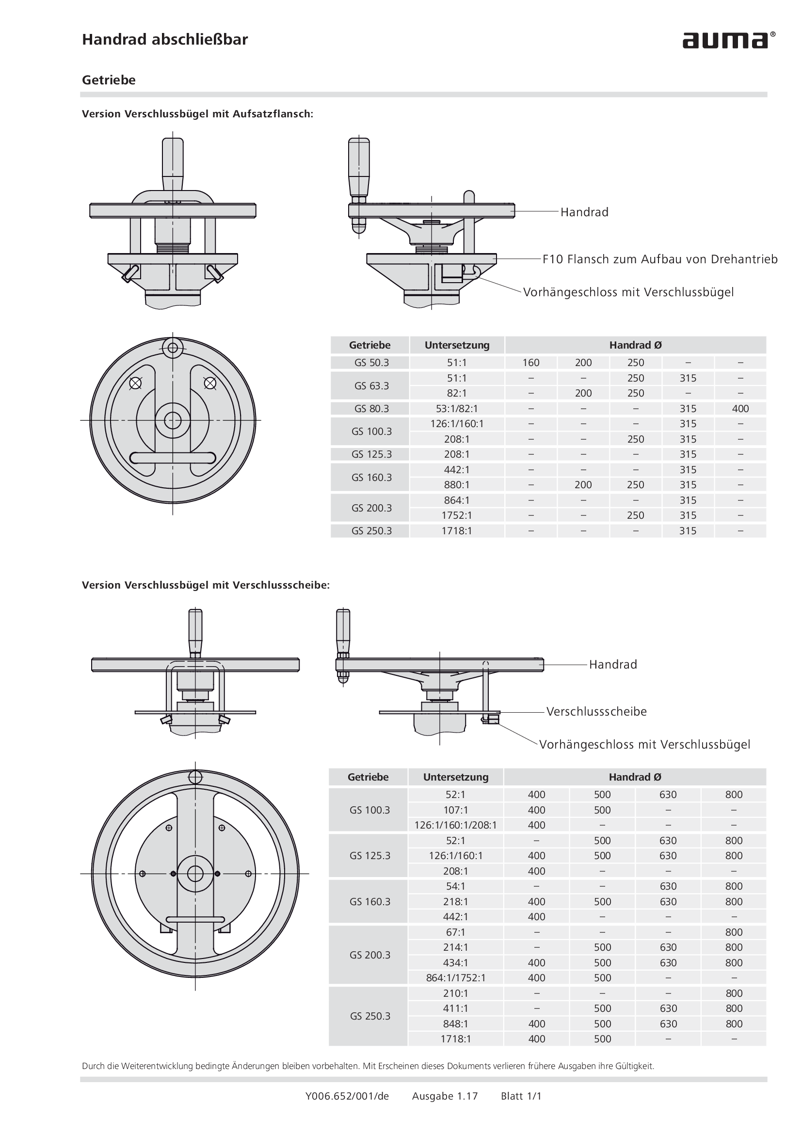
Handwheel lockable gearboxes GS 50.3 – GS 250.3, GF 50.3 – GF 250.3
Technical description
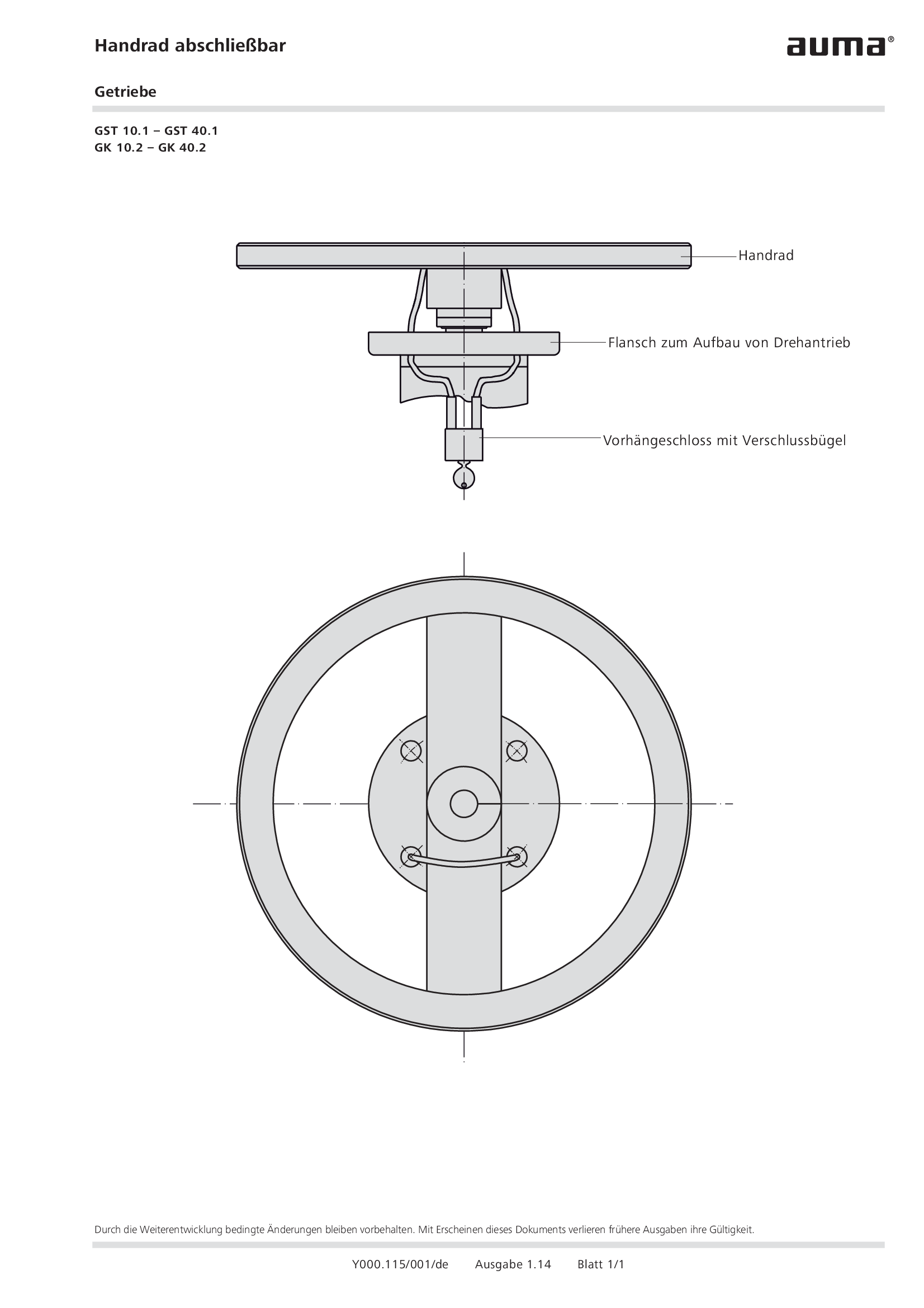
Handwheel lockable gearboxes GST 10.1 – GST 40.1, GK 10.2 – GK 40.2
Technical description
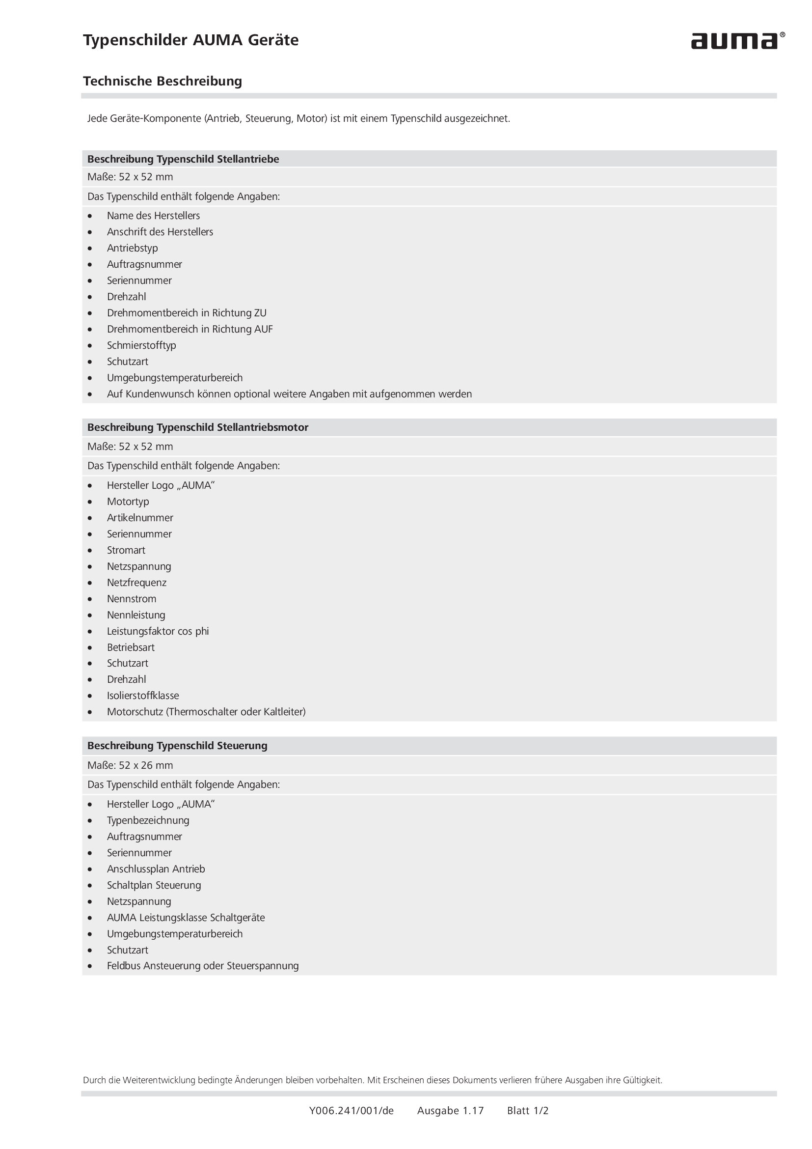
Name plates AUMA devices
Technical description
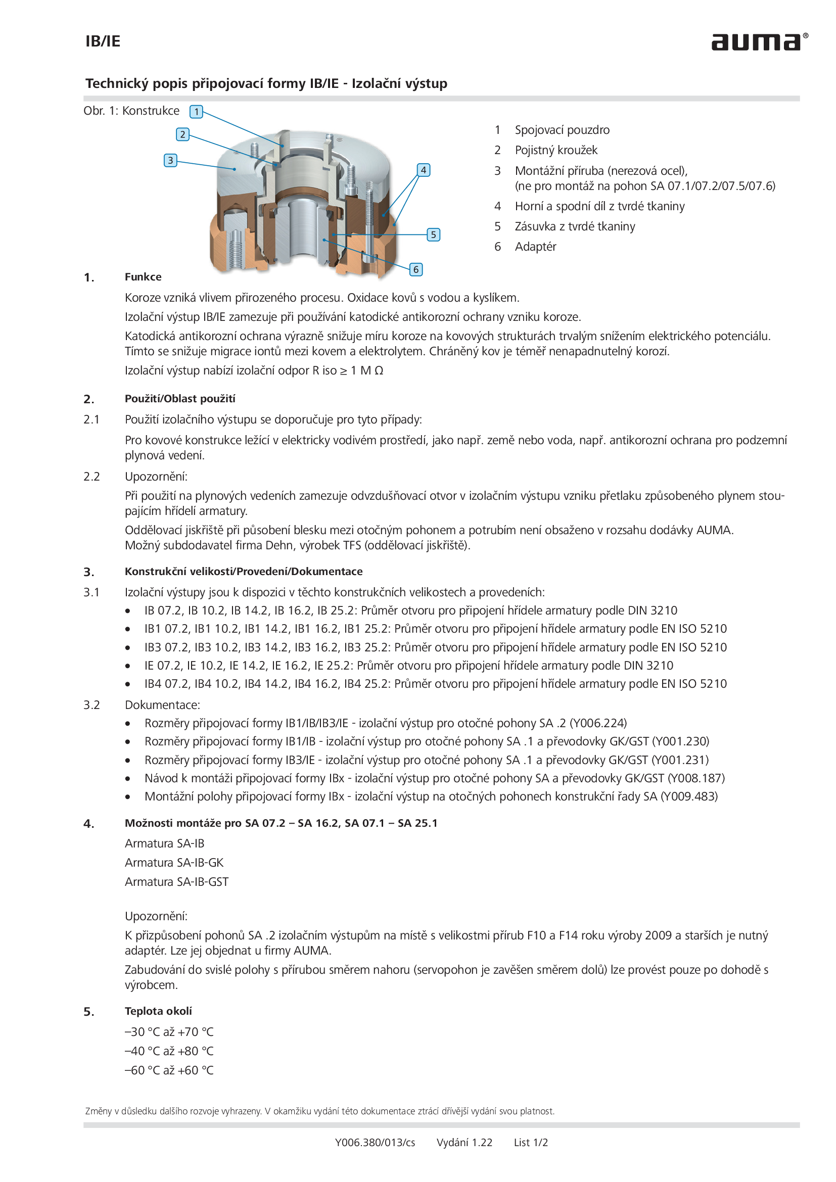
Output drive type IB/IE - Insulated output drive
Technical description
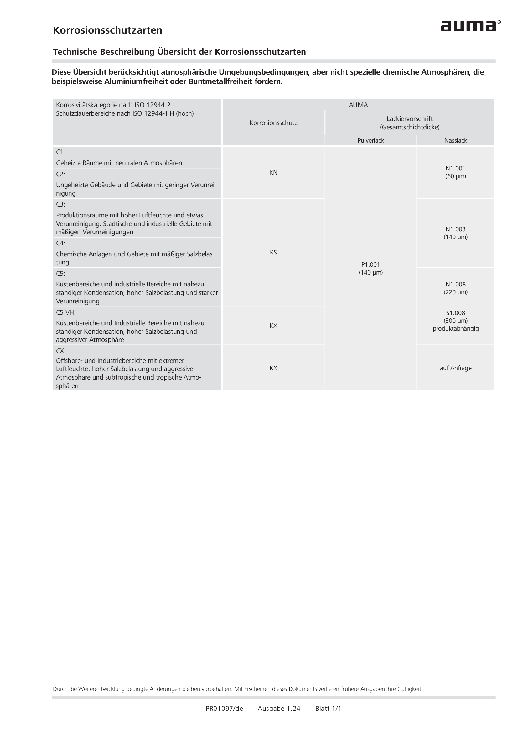
Overview Corrosion protection types
Technical description
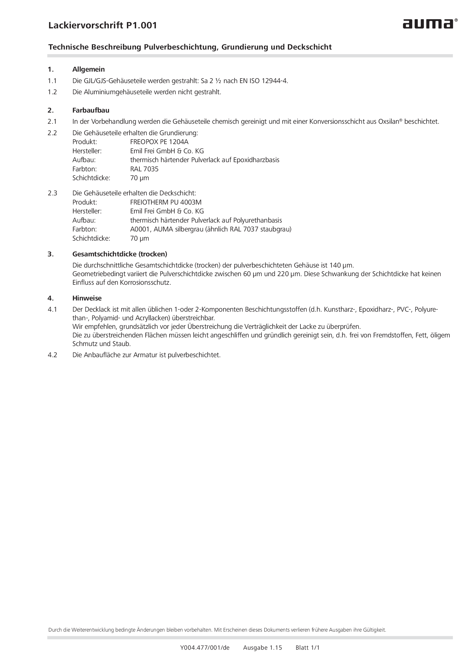
Painting specification P1.001 Powder coating, primer coating and finsh coating
Technical description
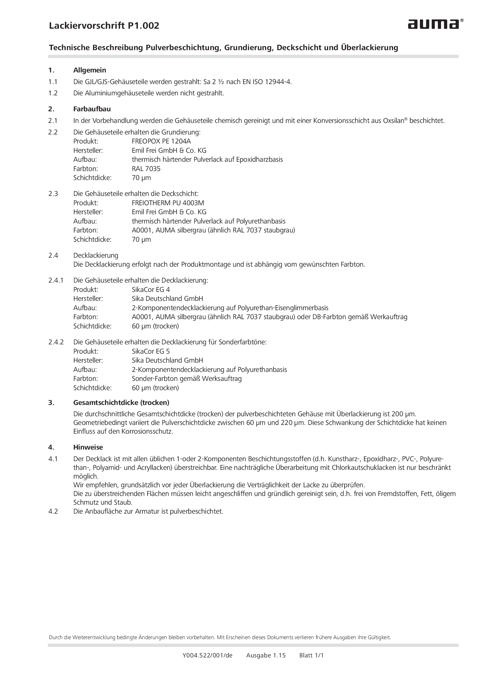
Painting specification P1.002 Powder coating, primer coating, finish coating and additional painting
Technical description
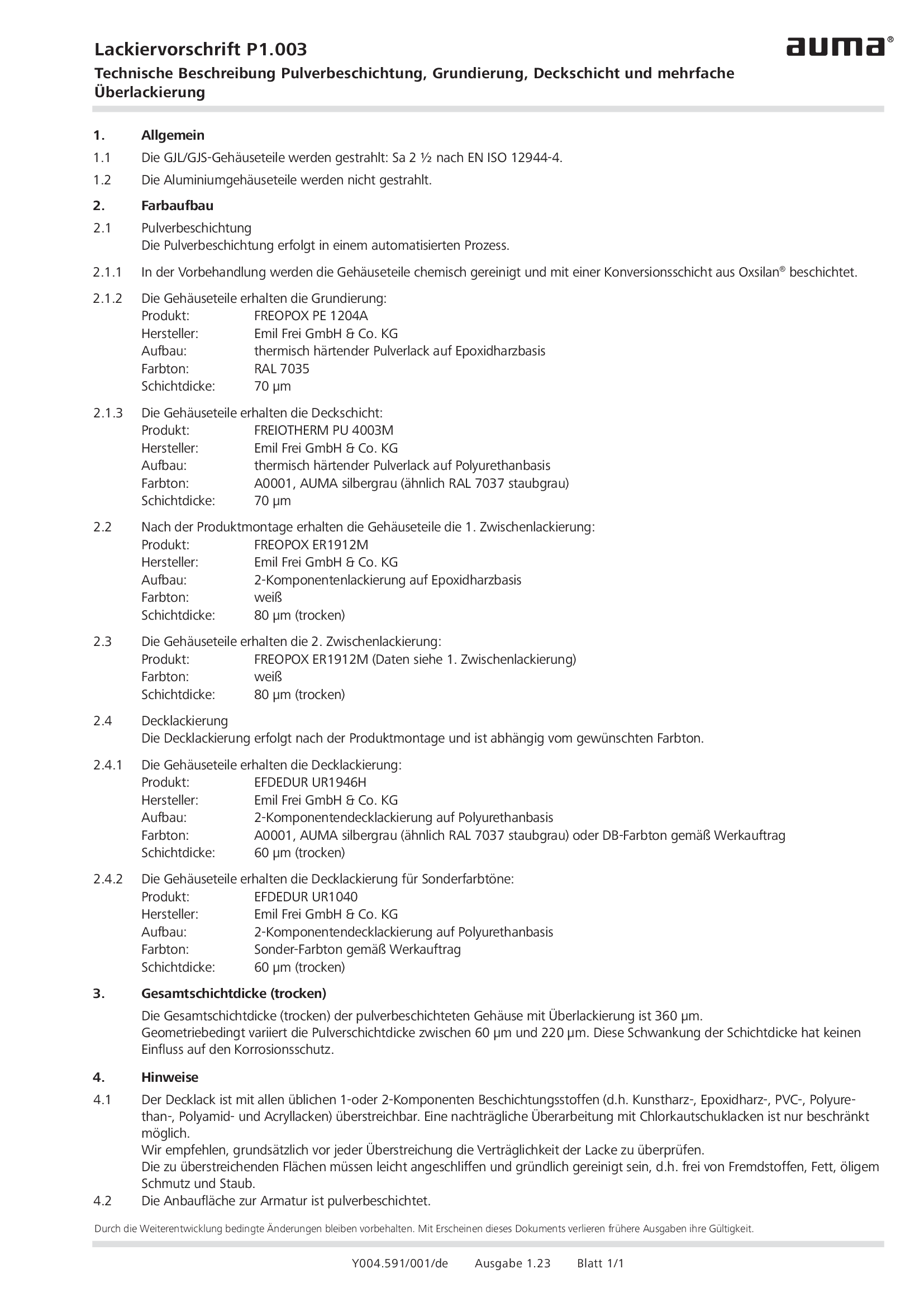
Painting specification P1.003 Powder coating, primer coating, finish coating and multi-layer painting
Technical description
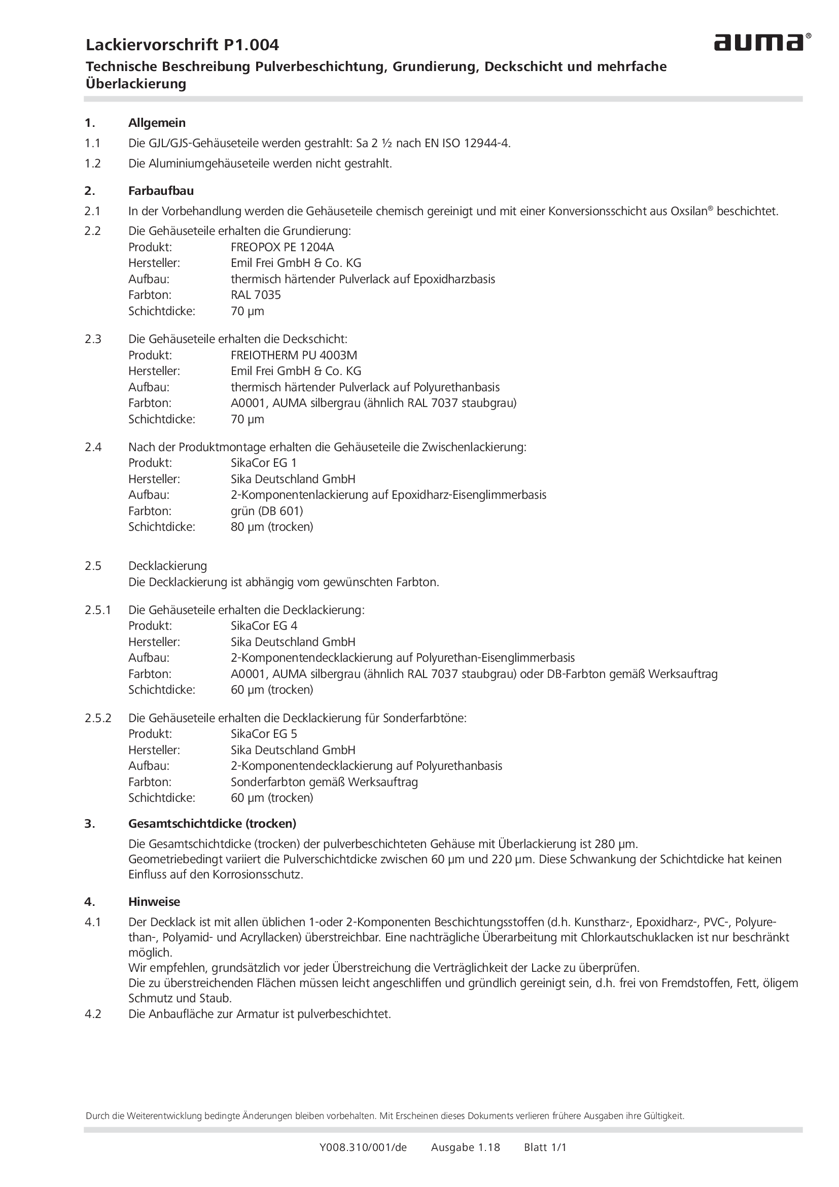
Painting specification P1.004 Powder coating, primer coating, finish coating and multi-layer painting
Technical description
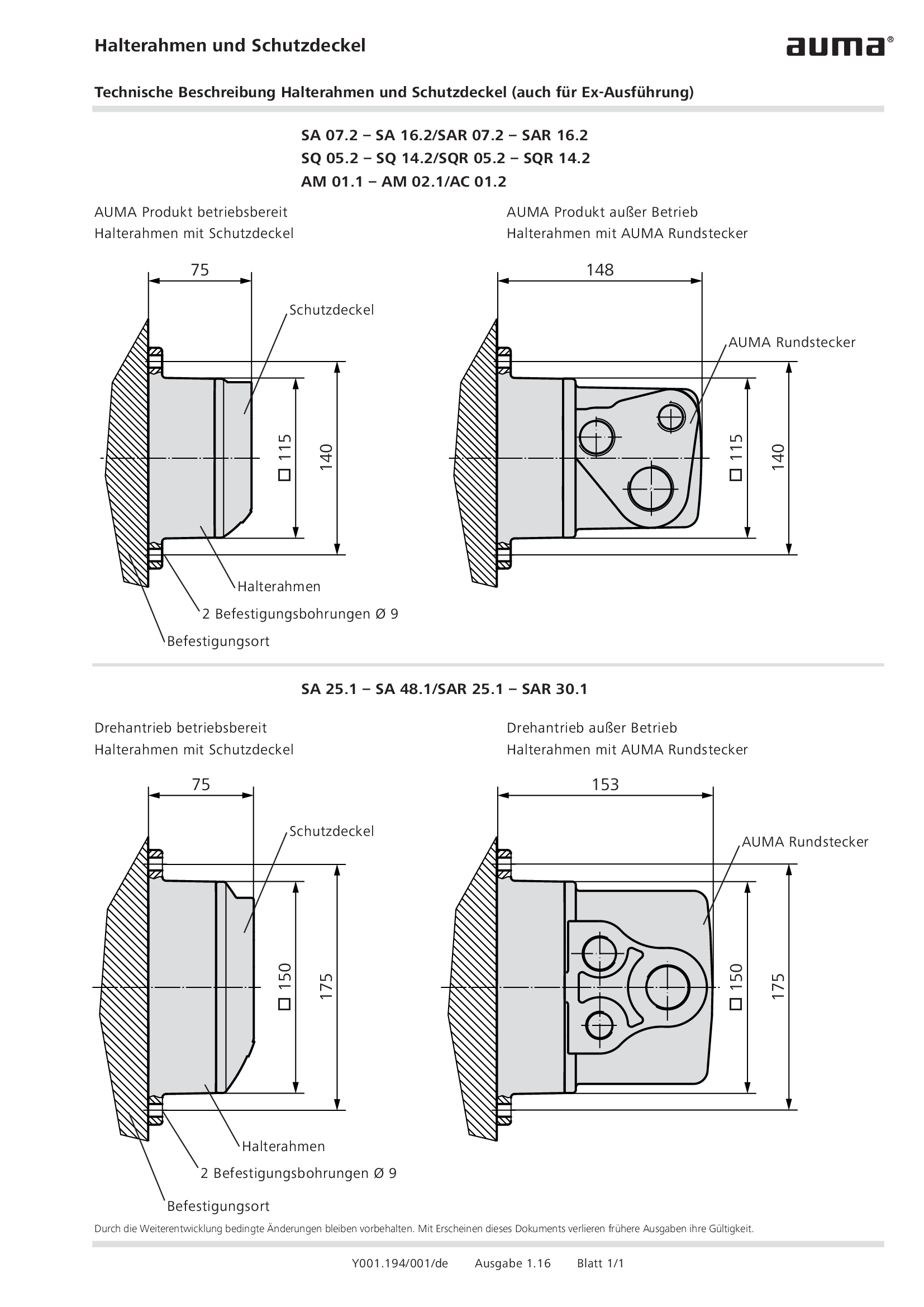
Parking frame and protection cover
Technical description

Position indicator with telescope protection tube
Technical description
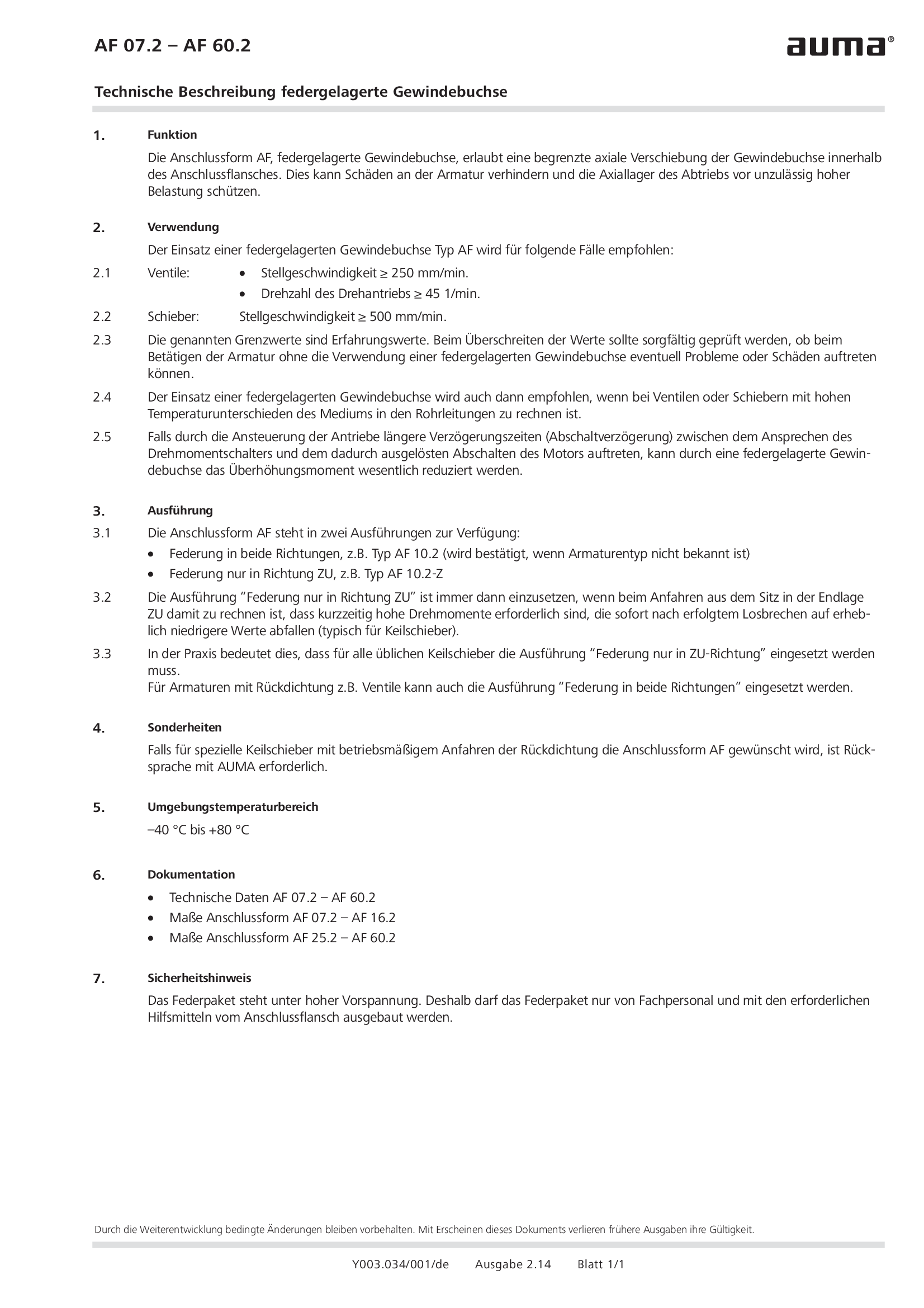
Spring loaded stem nut AF 07.2 - 60.2
Technical description
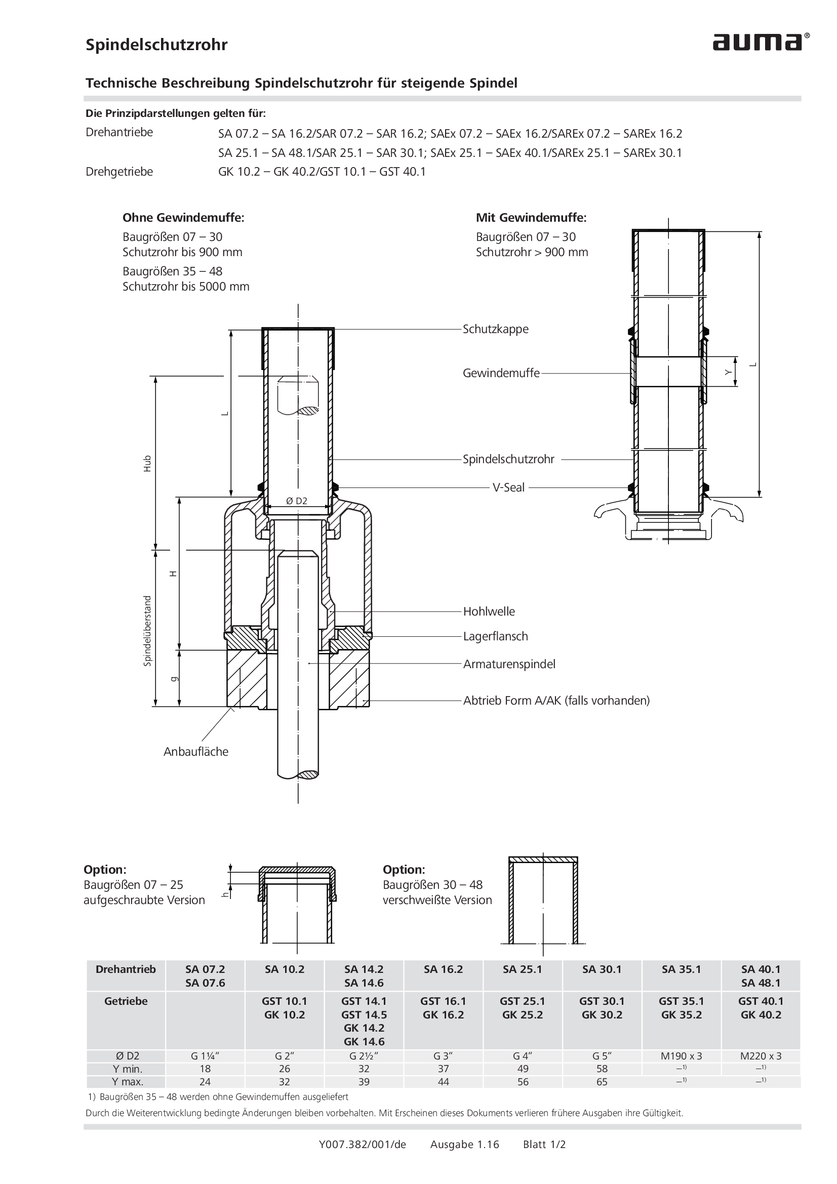
Stem protection tube for rising stem
Technical description
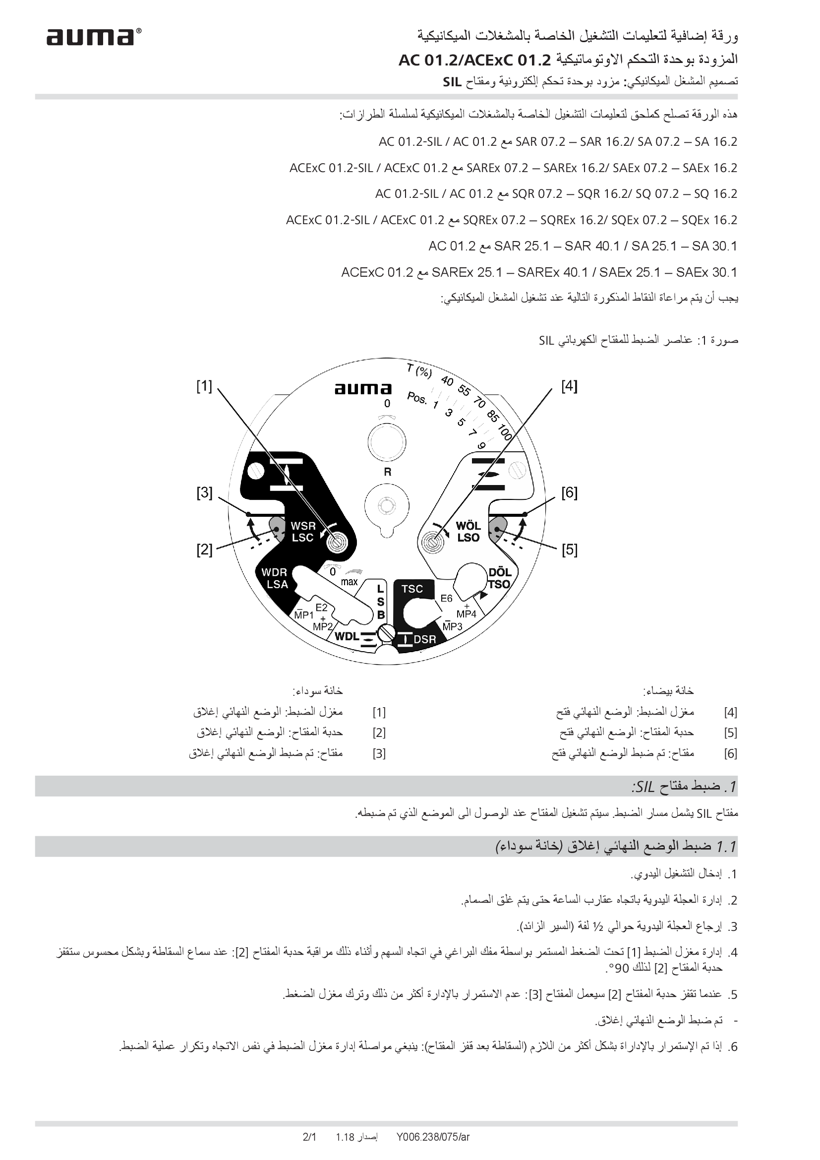
Supplement AUMATIC AC 01.2/ACExC 01.2, version actuators: with elektronic control unit (MWG) and SIL limit switching
Technical description
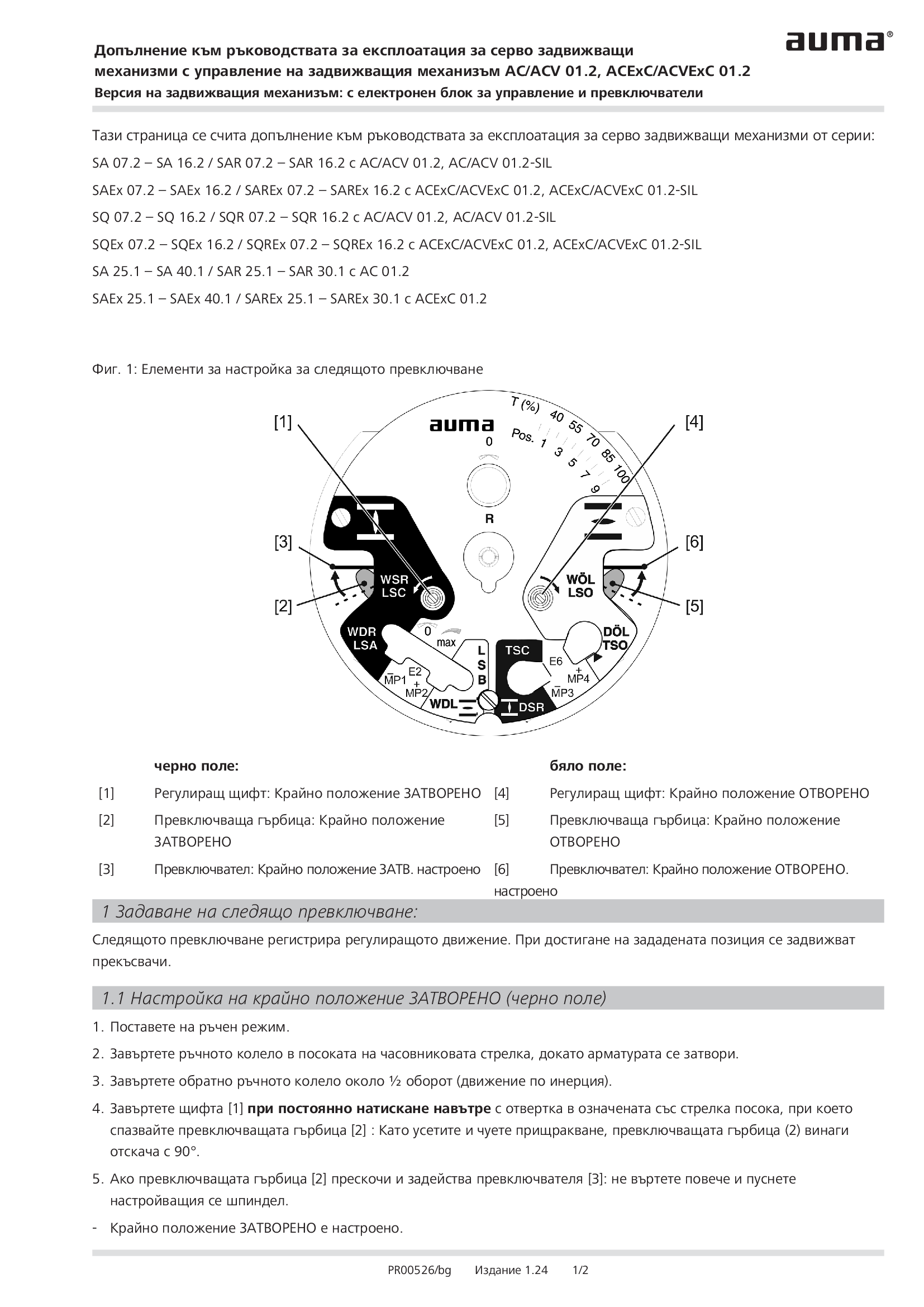
Supplement AUMATIC AC 01.2/ACExC 01.2, version actuators: with elektronic control unit (MWG) and limit switching
Technical description
Wiring diagram

A1: AUMATIC AC 01.2 position feedback signal 0/4 - 20 mA (potentiometer in actuator), basic version, reversing contactors OPEN, STOP, CLOSE, EMERGENCY (24 V DC), 6 programmable output contacts, AUMA power class A1 - A3
Wiring diagram

A1: AUMATIC ACExC 01.2 position feedback signal 0/4 - 20 mA (potentiometer in actuator),basic version, reversing contactors CLOSE, OPEN, STOP, EMERGENCY (24 V DC), 6 programmable output contacts, AUMA power class A1 - A3
Wiring diagram

A1N: AUMATIC AC 01.2 position/torque feedback signal 0/4 - 20 mA (MWG in actuator), reversing contactors OPEN, STOP, CLOSE, EMERGENCY (24 V DC), 6 programmable output contacts, AUMA power class A1 - A3
Wiring diagram

A1N: AUMATIC ACExC 01.2 position/torque feedback signal 0/4 - 20 mA (MWG in actuator), reversing contactors CLOSE, OPEN, STOP, EMERGENCY (24 V DC), 6 programmable output contacts, AUMA power class A1 - A3
Wiring diagram

A2: AUMATIC AC 01.2 positioner and postition feedback signal 0/4 - 20 mA (potentiometer in actuator), reversing contactors OPEN, STOP, CLOSE, EMERGENCY, MODE (24 V DC), 6 programmable output contacts, AUMA power class A1 - A3
Wiring diagram

A2: AUMATIC ACExC 01.2 positioner and position feedback signal 0/4 - 20 mA (potentiometer in actuator), reversing contactors MODE, CLOSE, OPEN, STOP, EMERGENCY (24 V DC), setpoint (0/4 - 20 mA), 6 programmable output contacts, AUMA power class A1 -
Wiring diagram

A2DP: AUMATIC AC 01.2 position feedback (potentiometer in actuator), basic version, reversing contactors, Profibus, AUMA power class A1 - A3
Wiring diagram

A2DP: AUMATIC ACExC 01.2 position feedback (potentiometer in actuator), basic version, reversing contactors, Profibus, AUMA power class A1 - A3
Wiring diagram

A2ENIP: AUMATIC AC 01.2 position feedback (potentiometer in actuator), basic version, reversing contactors, Ethernet/IP, AUMA power class A3 - A3
Wiring diagram

A2ENIP: AUMATIC ACExC 01.2 position feedback (potentiometer in actuator), basic version, reversing contactors, EtherNet/IP, AUMA power class A1 - A3
Wiring diagram

A2FF: AUMATIC AC 01.2 position feedback (potentiometer in actuator), basic version, Reversing contactors, Foundation Fieldbus FF, AUMA power classes A1 – A3
Wiring diagram

A2FF: AUMATIC ACExC 01.2 position feedback (potentiometer in actuator), basic version, reversing contactors, Foundation Fieldbus FF, AUMA power class A1 - A3
Wiring diagram

A2HRT: AUMATIC AC 01.2 position feedback (potentiometer in actuator), basic version, Reversing contactors, HART actuatorAUMA power classes A1 – A3
Wiring diagram

A2HRT: AUMATIC ACExC 01.2 position feedback (potentiometer in actuator), reversing contactors, HART actuator, AUMA power class A1 - A3
Wiring diagram

A2HRTCO: AUMATIC AC 01.2 position feedback (potentiometer in actuator), basic version, Reversing contactors, HART Current Output, AUMA power classes A1 – A3
Wiring diagram

A2HRTCO: AUMATIC ACExC 01.2 position feedback (potentiometer in actuator), basic version, reversing contactors, HART current output, AUMA power class A1 - A3
Wiring diagram

A2MB: AUMATIC AC 01.2 position feedback (potentiometer in actuator), basic version, reversing contactors, Modbus RTU, AUMA power class A1 - A3
Wiring diagram

A2MB: AUMATIC ACExC 01.2 position feedback (potentiometer in acuator), basic version, reversing contactors, Modbus, AUMA power class A1 - A3
Wiring diagram

A2MBTCP: AUMATIC AC 01.2 position feedback (potentiometer in actuator), basic version, Reversing contactors, Modbus TCP/IP, AUMA power classes A1 – A3
Wiring diagram

A2MBTCP: AUMATIC AC 01.2 position/torque feedback (MWG in actuator), Reversing contactors, Modbus TCP/IP, AUMA power classes A1 – A3
Wiring diagram

A2MBTCP: AUMATIC ACExC 01.2 position feedback (potentiometer in actuator), basic version, reversing contactors, Modbus TCP/IP, AUMA power class A1 - A3
Wiring diagram

A2N: AUMATIC AC 01.2 positioner and position/torque feedback signal 0/4 - 20 mA (MWG in actuator), , reversing contactors OPEN, STOP, CLOSE, EMERGENCY, MODE (24 V DC), 6 programmable output contacts, AUMA power class A1 - A3
Wiring diagram

A2N: AUMATIC ACExC 01.2 positioner and position/torque feedback signal 0/4 - 20 mA (MWG in actuator), reversing contactors MODE, CLOSE, OPEN, STOP, EMERGENCY (24 V DC), 6 programmable output contacts, AUMA power class A1 - A3
Wiring diagram

A2NDP: AUMATIC AC 01.2 position/torque feedback (MWG in actuator), reversing contactors, Profibus, AUMA power class A1 - A3
Wiring diagram

A2NDP: AUMATIC ACExC 01.2 position/torque feedback (MWG in actuator), reversing contactors, Profibus, AUMA power class A1 - A3
Wiring diagram

A2NENIP: AUMATIC AC 01.2, position/torque feedback (MWG in actuator, reversing contactors, Ethernet/IP, AUMA power class A1 - A 3
Wiring diagram

A2NENIP: AUMATIC ACExC 01.2 position/torque feedback (MWG in actuator), reversing contactors, EtherNet/IP, AUMA power class A1 - A3
Wiring diagram

A2NFF: AUMATIC AC 01.2 position/torque feedback (MWG in actuator), Reversing contactors, Foundation Fieldbus FF, AUMA power classes A1 – A3
Wiring diagram

A2NFF: AUMATIC ACExC 01.2 Stellungs-/Drehmomentrückmeldung (MWG im Stellanrieb), Schütze, Foundation Fieldbus FF, AUMA Leisungsklasse A1 - A3
Wiring diagram

A2NFF: AUMATIC ACExC 01.2 position/torque feedback (MWG in actuator), reversing contactors, Foundation Fieldbus FF, AUMA power class A1 - A3
Wiring diagram

A2NHRT: AUMATIC AC 01.2 position/torque feedback (MWG in actuator), Reversing contactors, HART actuator, AUMA power classes A1 – A3
Wiring diagram

A2NHRT: AUMATIC ACExC 01.2 position/torque feedback (MWG in actuator), reversing contactors, HART actuator, AUMA power class A1 - A3
Wiring diagram

A2NHRTCO: AUMATIC AC 01.2 position/torque feedback (MWG in actuator), Reversing contactors, HART Current Output, AUMA power classes A1 – A3
Wiring diagram

A2NHRTCO:AUMATIC ACExC 01.2 position/torque feedback (MWG in actuator), reversing contactors, HART current output, AUMA power class A1 - A3
Wiring diagram

A2NMB: AUMATIC AC 01.2 position/torque feedback (MWG in actuator), reversing contactors, Modbus RTU, AUMA power class A1 - A3
Wiring diagram

A2NMB: AUMATIC ACExC 01.2 position/torque feedback (MWG in actuator), reversing contactors, Modbus, AUMA power class A1 - A3
Wiring diagram

A2NMBTCP: AUMATIC ACExC 01.2 position/torque feedback (MWG in actuator), reversing contactors, Modbus TCP/IP, AUMA power class A1 - A3
Wiring diagram

A3: AUMATIC AC 01.2 positioner and position feedback signal 0/4 - 20 mA (potentiometer in actuator), thyristors OPEN, STOP, CLOSE, EMERGENCY, MODE (24 V DC), 6 programmable output contacts, AUMA power class B1/B2
Wiring diagram

A3: AUMATIC AC 01.2 positioner and position feedback signal 0/4 - 20 mA (potentiometer in actuator), thyristors OPEN, STOP, CLOSE, EMERGENCY, MODE (24 V DC), 6 programmable output contacts, AUMA power class B3
Wiring diagram

A3: AUMATIC ACExC 01.2 positioner and position feedback signal 0/4 - 20 mA (potentiometer in actuator), thyristors MODE, CLOSE, OPEN, STOP, EMERGENCY (24 V DC), setpoint (0/4 - 20 mA) 6 programmable output contacts, AUMA power class B1/B2
Wiring diagram

A3: AUMATIC ACExC 01.2 positioner and position feedback signal 0/4 - 20 mA (potentiometer in actuator), thyristors MODE, CLOSE, OPEN, STOP, EMERGENCY (24 V DC), setpoint (0/4 - 20 mA) 6 programmable output contacts, AUMA power class B3
Wiring diagram

A3DP: AUMATIC AC 01.2 position feedback (potentiometer in actuator), thyristors, Profibus, AUMA power class B1/B2
Wiring diagram

A3DP: AUMATIC AC 01.2 position feedback (potentiometer in actuator), thyristors, Profibus, AUMA power class B2
Wiring diagram

A3DP: AUMATIC ACExC 01.2 position feedback (potentiometer in actuator), thyristors, Profibus, AUMA power class B1/B2
Wiring diagram

A3DP: AUMATIC ACExC 01.2 position feedback (potentiometer in actuator), thyristors, Profibus, AUMA power class B3
Wiring diagram

A3ENIP: AUATIC AC 01.2 postition feedback (potentiometer in actuator), Thyristors, EtherNet/IP, AUMA power class B1/B2
Wiring diagram

A3ENIP: AUATIC AC 01.2 postition feedback (potentiometer in actuator), Thyristors, EtherNet/IP, AUMA power class B3
Wiring diagram

A3ENIP: AUATIC ACExC 01.2 position feedback (potentiometer in actuator), Thyristors, EtherNet/IP, AUMA power class B1/B2
Wiring diagram

A3ENIP: AUATIC ACExC 01.2 position feedback (potentiometer in actuator), Thyristors, EtherNet/IP, AUMA power class B3
Wiring diagram

A3FF: AUMATIC AC 01.2 position feedback (potentiometer in actuator), Thyristors, Foundation Fieldbus FF, AUMA power class B1/B2
Wiring diagram

A3FF: AUMATIC AC 01.2 position feedback (potentiometer in actuator), Thyristors, Foundation Fieldbus FF, AUMA power class B3
Wiring diagram

A3FF: AUMATIC ACExC 01.2 position feedback (potentiometer in actuator), Thyristors, Foundation Fieldbus FF, AUMA power class B1/B2
Wiring diagram

A3FF: AUMATIC ACExC 01.2 position feedback (potentiometer in actuator), Thyristors, Foundation Fieldbus FF, AUMA power class B3
Wiring diagram

A3HRT: AUMATIC AC 01.2 position feedback (potentiometer in actuator), Thyristors, HART actuator, AUMA power class B1/B2
Wiring diagram

A3HRT: AUMATIC AC 01.2 position feedback (potentiometer in actuator), Thyristors, HART actuator, AUMA power class B3
Wiring diagram

A3HRT: AUMATIC ACExC 01.2 position feedback (potentiometer in actuator) Thyristors, HART actuator, AUMA power class B1/B2
Wiring diagram

A3HRT: AUMATIC ACExC 01.2 position feedback (potentiometer in actuator) Thyristors, HART actuator, AUMA power class B3
Wiring diagram

A3HRTCO: AUMATIC AC 01.2 position feedback (potentiometer in actuator), Thyristors, HART Current Output, AUMA power class B1/B2
Wiring diagram

A3HRTCO: AUMATIC AC 01.2 position feedback (potentiometer in actuator), Thyristors, HART Current Output, AUMA power class B3
Wiring diagram

A3HRTCO: AUMATIC ACExC 01.2 position feedback (potentiometer in actuator), Thyristors, HART current output, AUMA power class B1/B2
Wiring diagram

A3HRTCO: AUMATIC ACExC 01.2 position feedback (potentiometer in actuator), Thyristors, HART current output, AUMA power class B3
Wiring diagram

A3MB: AUMATIC AC 01.2 position feedback (potentiometer in actuator), thyristors, Modbus, AUMA power class B1/B2
Wiring diagram

A3MB: AUMATIC AC 01.2 position feedback (potentiometer in actuator), thyristors, Modbus, AUMA power class B3
Wiring diagram

A3MB: AUMATIC ACExC 01.2 position feedback (potentiometer in actuator), thyristors, Modbus, AUMA power class B1/B2
Wiring diagram

A3MB: AUMATIC ACExC 01.2 position feedback (potentiometer in actuator), thyristors, Modbus, AUMA power class B3
Wiring diagram

A3MBTCP: AUMATIC AC 01.2 position feedback (potentiometer in actuator), Thyristors, Modbus TCP/IP, AUMA power class B1/B2
Wiring diagram

A3MBTCP: AUMATIC AC 01.2 position feedback (potentiometer in actuator), Thyristors, Modbus TCP/IP, AUMA power class B3
Wiring diagram

A3MBTCP: AUMATIC ACExC 01.2 position feedback (potentiometer in actuator), Thyristors, Modbus TCP/IP, AUMA power class B1/B2
Wiring diagram

A3MBTCP: AUMATIC ACExC 01.2 position feedback (potentiometer in actuator), Thyristors, Modbus TCP/IP, AUMA power class B3
Wiring diagram

A3N: AUMATIC AC 01.2 positioner and position/torque feedback signal 0/4 - 20 mA (MWG in actuator), thyristors OPEN, STOP, CLOSE, EMERGENCY, MODE (24 V DC), 6 programmable output contacts, AUMA power class B1/B2
Wiring diagram

A3N: AUMATIC AC 01.2 positioner and position/torque feedback signal 0/4 - 20 mA (MWG in actuator), thyristors OPEN, STOP, CLOSE, EMERGENCY, MODE (24 V DC), 6 programmable output contacts, AUMA power class B3
Wiring diagram

A3N: AUMATIC ACExC 01.2 positioner and position/torque feedback signal 0/4 - 20 mA (MWG in actuator), thyristors MODE, CLOSE, OPEN, STOP, EMERGENCY (24 V DC), setpoint (0/4 - 20 mA), 6 programmable output contacts, AUMA power class B1/B2
Wiring diagram

A3N: AUMATIC ACExC 01.2 positioner and position/torque feedback signal 0/4 - 20 mA (MWG in actuator), thyristors MODE, CLOSE, OPEN, STOP, EMERGENCY (24 V DC), setpoint (0/4 - 20 mA), 6 programmable output contacts, AUMA power class B3
Wiring diagram

A3NDP: AUMATIC AC 01.2 position/torque feedback (MWG in actuator), thyristors, Profibus, AUMA power class B1/B2
Wiring diagram

A3NDP: AUMATIC AC 01.2 position/torque feedback (MWG in actuator), thyristors, Profibus, AUMA power class B3
Wiring diagram

A3NDP: AUMATIC ACExC 01.2 position/torque feedback (MWG in actuator), thyristors, Profibus, AUMA power class B1/B2
Wiring diagram

A3NDP: AUMATIC ACExC 01.2 position/torque feedback (MWG in actuator), thyristors, Profibus, AUMA power class B3
Wiring diagram

A3NENIP: AUMATIC AC 01.2 position/torque feedback (MWG in actuator), Thyristors, Ethernet/IP, AUMA power class B1/B2
Wiring diagram

A3NENIP: AUMATIC AC 01.2 position/torque feedback (MWG in actuator), Thyristors, Ethernet/IP, AUMA power class B3
Wiring diagram

A3NENIP: AUMATIC ACExC 01.2 position/torque feedback (MWG in actuator), Thyristors, EtherNet/IP, AUMA power class B1/B2
Wiring diagram

A3NENIP: AUMATIC ACExC 01.2 position/torque feedback (MWG in actuator), Thyristors, EtherNet/IP, AUMA power class B3
Wiring diagram

A3NFF: AUMATIC AC 01.2 position/torque feedback (MWG in actuator), Thyristors, Foundation Fieldbus FF, AUMA power class B1/B2
Wiring diagram

A3NFF: AUMATIC AC 01.2 position/torque feedback (MWG in actuator), Thyristors, Foundation Fieldbus FF, AUMA power class B3
Wiring diagram

A3NFF: AUMATIC ACExC 01.2 position/torque feedback (MWG in actuator), Thyristors, Foundation Fieldbus FF, AUMA power class B1/B2
Wiring diagram

A3NFF: AUMATIC ACExC 01.2 position/torque feedback (MWG in actuator), Thyristors, Foundation Fieldbus FF, AUMA power class B3
Wiring diagram

A3NHRT: AUMATIC AC 01.2 position/torque feedback (MWG in actuator), Thyristors, HART actuator, AUMA power class B1/B2
Wiring diagram

A3NHRT: AUMATIC AC 01.2 position/torque feedback (MWG in actuator), Thyristors, HART actuator, AUMA power class B3
Wiring diagram

A3NHRT: AUMATIC ACExC 01.2 position/torque feedback (MWG in actuator), Thyristors, HART actuator, AUMA power class B1/B2
Wiring diagram

A3NHRT: AUMATIC ACExC 01.2 position/torque feedback (MWG in actuator), Thyristors, HART actuator, AUMA power class B3
Wiring diagram

A3NHRTCO: AUMATIC AC 01.2 position/torque feedback (MWG in actuator), Thyristors, HART actuator, AUMA power class B1/B2
Wiring diagram

A3NHRTCO: AUMATIC AC 01.2 position/torque feedback (MWG in actuator), Thyristors, HART actuator, AUMA power class B3
Wiring diagram

A3NHRTCO: AUMATIC ACExC 01.2 position/torque feedback (MWG in actuator), Thyristors, HART current output, AUMA power class B1/B2
Wiring diagram

A3NHRTCO: AUMATIC ACExC 01.2 position/torque feedback (MWG in actuator), Thyristors, HART current output, AUMA power class B3
Wiring diagram

A3NMB: AUMATIC AC 01.2 position/torque feedback (MWG in actuator), thyristors, Modbus RTU, AUMA power class B1/B2
Wiring diagram

A3NMB: AUMATIC AC 01.2 position/torque feedback (MWG in actuator), thyristors, Modbus RTU, AUMA power class B3
Wiring diagram

A3NMB: AUMATIC ACExC 01.2 position/torque feedback (MWG in actuator), thyristors, Modbus, AUMA power class B1/B2
Wiring diagram

A3NMB: AUMATIC ACExC 01.2 position/torque feedback (MWG in actuator), thyristors, Modbus, AUMA power class B3
Wiring diagram

A3NMBTCP: AUMATIC AC 01.2 position/torque feedback (MWG in actuator), Thyristors, Modbus TCP/IP, AUMA power class B1/B2
Wiring diagram

A3NMBTCP: AUMATIC AC 01.2 position/torque feedback (MWG in actuator), Thyristors, Modbus TCP/IP, AUMA power class B3
Wiring diagram

A3NMBTCP: AUMATIC ACExC 01.2 position/torque feedback (MWG in actuator), Thyristors, Modbus TCP/IP, AUMA power class B1/B2
Wiring diagram

A3NMBTCP: AUMATIC ACExC 01.2 position/torque feedback (MWG in actuator), Thyristors, Modbus TCP/IP, AUMA power class B3
Wiring diagram

A3NPN: AUMATIC AC 01.2, position/torque feedback (MWG in actuator), Thyristors, Profinet, AUMA power class B1/B2
Wiring diagram

A3NPN: AUMATIC AC 01.2, position/torque feedback (MWG in actuator), Thyristors, Profinet, AUMA power class B3
Wiring diagram

A3PN: AUMATIC AC 01.2 position feedback (potentiometer in actuator), Thyristors, Profinet, AUMA power class B1/B2
Wiring diagram

A3PN: AUMATIC AC 01.2 position feedback (potentiometer in actuator), Thyristors, Profinet, AUMA power class B3
Wiring diagram

A4DP: AUMATIC AC 01.2 positioner and position feedback signal 0/4 - 20 mA (potentiometer in actuator),basic version, reversing contactors MODE, CLOSE, OPEN, STOP, EMERGENCY, I/O (24 V DC), Profibus DP, AUMA power class A1 - A3
Wiring diagram

A4DP: AUMATIC ACExC 01.2 positioner and position feedbacck signal 0/4 - 20 mA (potentiometer in actuator), basic version, reversing contactors MODE, CLOSE, OPEN, STOP, EMERGENCY, I/O (24 V DC), 6 programmable output contacts, Profibus, power class A
Wiring diagram

A4ENIP: AUMATIC AC 01.2 positioner and position feedback signal 0/4 - 20 mA (potentiometer in actuator), basic version, reversing contactors MODE, CLOSE, OPEN, STOP, EMERGENCY, I/O (24 V DC), 6 programmable output contacts Ethernet/IP, AUMA power class
Wiring diagram

A4ENIP: AUMATIC ACExC 01.2 positioner and position feedback signal 0/4 - 20 mA (poti in actuator), basic version, reversing contactors MODE, CLOSE, OPEN, STOP, EMERGENCY, I/O (24 V DC), 6 programmable output contacts, EtherNet/IP, AUMA power class A1-A3
Wiring diagram

A4FF: AUMATIC AC 01.2 positioner and position feedback signal 0/4 – 20 mA (potentiometer in actuator), basic version, Reversing contactors MODE, CLOSE, OPEN, STOP, EMERGENCY, I/O (24V DC), 6 programmable output contacts, FF, AUMA power classes A1-A3
Wiring diagram

A4FF: AUMATIC ACExC 01.2 positioner and position feedback signal 0/4-20 mA (poti in actuator), basic version, reversing contactors MODE, CLOSE, OPEN, STOP, EMERGENCY, I/O (24 V DC),6 prorammable output contact, Foundation Fieldbus, AUMA power class A1-A3
Wiring diagram

A4HRT: AUMATIC AC 01.2 positioner and position feedback signal 0/4-20mA (potentiometer in actuator), basic version, Reversing contactors MODE, CLOSE, OPEN, STOP, EMERGENCY, I/O (24V DC), 6 programmable output contacts, HART, AUMA power classes A1 – A3
Wiring diagram

A4HRTCO: AUMATIC AC 01.2 positioner and position feedback signal 0/4-20mA (potentiometer in actuator), basic version, Reversing contactors MODE, CLOSE, OPEN, STOP, EMERGENCY, I/O (24V DC), 6 programmable output contacts, HART, AUMA power classes A1-A3
Wiring diagram

A4MB: AUMATIC AC 01.2 positioner and position feedback signal 0/4 - 20 mA (potentiometer in actuator), basic version, reversing contactors MODE, CLOSE, OPEN, STOP, EMERGENCY, I/O (24 V DC), 6programmable output contacts, Modbus RTU, power class A1 - A3
Wiring diagram

A4MB: AUMATIC ACExC 01.2 positioner and position feedback signal 0/4 - 20 mA (potentiometer in actuator), basic version, reversing contactors MODE, CLOSE, OPEN, STOP, EMERGENCY, I/O(24 V DC), 6 programmable output contacts, Modbus, AUMA power class
Wiring diagram

A4N: AUMATIC AC 01.2 process controller and position/torque feedback signal 0/4 - 20 mA (MWG in actuator), thyristors CLOSE, OPEN, STOP, EMERGENCY, MODE (24 V DC), 6 programmable output contacts, AUMA power class B1/B2
Wiring diagram

A4NDP: AUMATIC AC 01.2 positioner and position/torque feedback signal 0/4 - 20 mA (MWG in actuator), reversing contactors MODE, CLOSE, OPEN, STOP, EMERGENCY, I/O (24 V DC), 6 programmable output contacts, Profibus DP, AUMA power class A1 - A3
Wiring diagram

A4NDP: AUMATIC ACExC 01.2 positioner and position/torque feedback signal 0/4 - 20 mA (MWG in actuator), reversing contactors MODE, CLOSE, OPEN, STOP, EMERGENCY, I/O (24 V DC), 6 programmable output contacts, Profibus, AUMA power class A1 - A3
Wiring diagram

A4NENIP: AUMATIC AC 01.2 positioner and position/torque feedbacksignal 0/4 - 20 mA (MWG in actuator), reversing contactors MODE, CLOSE, OPEN, STOP, EMERGENCY, I/O (24 v DC), 6 programmable output contacts, EtherNet/IP, AUMA power class A1 - A3
Wiring diagram

A4NENIP: AUMATIC ACExC 01.2 positioner and position/torque feedback signal 0/4 - 20 mA (MWG in actuator), reversing contactors MODE, CLOSE, OPEN, STOP, EMERGENCY, I/O (24 V DC), 6 programmable output contacts, EtherNet/IP, AUMA power class A1 - A3
Wiring diagram

A4NFF: AUMATIC ACExC 01.2 positioner and position/torque feedback signal 0/4 - 20 mA (MWG in actuator), reversing contactors MODE, CLOSE, OPEN, STOP, EMERGENCY, I/O (24 V DC), 6 programmable output contacts, Foundation Fieldbus, AUMA power class A1 - A3
Wiring diagram

A4NHRT: AUMATIC AC 01.2 positioner and position/torque feedback signal 0/4 – 20 mA (MWG in actuator), Reversing contactors MODE, CLOSE, OPEN, STOP, EMERGENCY, I/O (24 V DC), 6 programmable output contacts, HART, AUMA power classes A1 – A3
Wiring diagram

A4NHRT: AUMATIC ACExC 01.2 positioner and position/torque feedback signal 0/4 - 20 mA MWG in actuator), reversing contactors MODE, CLOSE, OPEN, STOP, EMERGENCY, I/O (24 V DC), 6 programmable output contacts, HART actuator, AUMA power class A1 - A3
Wiring diagram

A4NHRTCO: AUMATIC AC 01.2 position/torque feedback (MWG in actuator), Reversing contactors MODE, CLOSE, OPEN, STOP, EMERGENCY, I/O (24 V DC), 6 programmable output contacts, HART current output, AUMA power classes A1 – A3
Wiring diagram

A4NHRTCO: AUMATIC ACExC 01.2 position/torque feedback (MWG in actuator), reversing contactors MODE, CLOSE, OPEN, STOP, EMERGENCY, I/O (24 V DC), 6 programmable output contacts, HART current output, AUMA power class A1 - A3
Wiring diagram

A4NMB: AUMATIC AC 01.2 positioner and position/torque feedback signal 0/4 - 20 mA (MWG in actuator), reversing contactors MODE, CLOSE, OPEN, STOP, EMERGENCY, I/O (24 V DC), 6 programmable output contacts, Modbus RTU, AUMA power class A1 - A3
Wiring diagram

A4NMB: AUMATIC ACExC 01.2 positioner and position/torque feedback signal 0/4 - 20 mA (MWG in actuator), reversing contactors MODE, CLOSE, OPEN, STOP, EMERGENCY, I/O (24 V DC), 6 programmable output contacts, Modbus, AUMA power class A1 - A3
Wiring diagram

A4NMBTCP: AUMATIC AC 01.2 positioner and position/torque feedback signal 0/4 – 20 mA (MWG in actuator), Reversing contactors MODE, CLOSE, OPEN, STOP, EMERGENCY, I/O (24 V DC), 6 programmable output contacts, Modbus RTU, AUMA power classes A1 – A3
Wiring diagram

A4NMBTCP: AUMATIC ACExC 01.2 positioner and position/torque feedback signal 0/4 - 20 mA (MWG in actuator), reversing contactors MODE, CLOSE, OPEN, STOP, EMERGENCY, I/O (24 V DC), 6 programmable output contacts, Modbus TPC/IP, AUMA power class A1 - A3
Wiring diagram

A5DP: AUMATIC AC 01.2 positioner and position feedback signal 0/4 - 20 mA (potentiometer in actuator), thyristors MODE, CLOSE, OPEN, STOP, EMERGENCY, I/O (24 V DC), 6 programmable output contacts, Profibus DP, AUMA power class B1/B2
Wiring diagram

A5DP: AUMATIC AC 01.2 positioner and position feedback signal 0/4 - 20 mA (potentiometer in actuator), thyristors MODE, CLOSE, OPEN, STOP, EMERGENCY, I/O (24 V DC), 6 programmable output contacts, Profibus DP, AUMA power class B3
Wiring diagram

A5DP: AUMATIC ACExC 01.2 positioner and position feedback signal 0/4 - 20 mA (potentiometer in actuator), thyristors MODE, CLOSE, STOP, EMERGENCY, I/O (24 V DC), 6 programmable ouput contacts, Profibus, AUMA power class B1/B2
Wiring diagram

A5DP: AUMATIC ACExC 01.2 positioner and position feedback signal 0/4 - 20 mA (potentiometer in actuator), thyristors MODE, CLOSE, STOP, EMERGENCY, I/O (24 V DC), 6 programmable ouput contacts, Profibus, AUMA power class B3
Wiring diagram

A5ENIP: AUMATIC AC 01.2 positioner and position feedback signal 0/4 - 20 mA (potentiometer in actuator), Thyristors, MODE, CLOSE, OPEN, STOP, EMERGENCY, I/O (24 V DC), 6 programmable output contacts, EtherNet/IP, AUMA power class B1 / B2
Wiring diagram

A5ENIP: AUMATIC AC 01.2 positioner and position feedback signal 0/4 - 20 mA (potentiometer in actuator), Thyristors, MODE, CLOSE, OPEN, STOP, EMERGENCY, I/O (24 V DC), 6 programmable output contacts, EtherNet/IP, AUMA power class B3
Wiring diagram

A5ENIP: AUMATIC ACExC 01.2 positioner and position feedback signal 0/4 - 20 mA (potentiometer in actuator), Thyristors MODE, CLOSE, OPEN, STOP, EMERGENCY, I/O (24 V DC), 6 programmable output contacts, EtherNet/IP, AUMA power class B1/B2
Wiring diagram

A5ENIP: AUMATIC ACExC 01.2 positioner and position feedback signal 0/4 - 20 mA (potentiometer in actuator), Thyristors MODE, CLOSE, OPEN, STOP, EMERGENCY, I/O (24 V DC), 6 programmable output contacts, EtherNet/IP, AUMA power class B3
Wiring diagram

A5FF: AUMATIC AC 01.2 positioner and position feedback signal 0/4 – 20 mA (potentiometer in actuator), Thyristors MODE, CLOSE, OPEN, STOP, EMERGENCY, I/O (24 V DC), 6 programmable output contacts, Foundation Fieldbus, AUMA power class B1/B2
Wiring diagram

A5FF: AUMATIC AC 01.2 positioner and position feedback signal 0/4 – 20 mA (potentiometer in actuator), Thyristors MODE, CLOSE, OPEN, STOP, EMERGENCY, I/O (24 V DC), 6 programmable output contacts, Foundation Fieldbus, AUMA power class B3
Wiring diagram

A5FF: AUMATIC AC 01.2 positioner and position feedback signal 0/4 – 20 mA (potentiometer in actuator), Thyristors MODE, CLOSE, OPEN, STOP, EMERGENCY, I/O (24 V DC), 6 programmable output contacts,´Foundation Fieldbus, AUMA power class B1/B2
Wiring diagram

A5FF: AUMATIC ACExC 01.2 positioner and position feedback signal 0/4-20 mA (potentiometer in actuator), Thyristors MODE, CLOSE, OPEN, STOP, EMERGENCY, I/O (24 V DC), 6 programmable output contacts, Foundation Fieldbus FF, AUMA power class B1/B2
Wiring diagram

A5FF: AUMATIC ACExC 01.2 positioner and position feedback signal 0/4-20 mA (potentiometer in actuator), Thyristors MODE, CLOSE, OPEN, STOP, EMERGENCY, I/O (24 V DC), 6 programmable output contacts, Foundation Fieldbus FF, AUMA power class B3
Wiring diagram

A5HRT: AUMATIC AC 01.2 positioner and position feedback signal 0/4 – 20 mA (potentiometer in actuator), Thyristors MODE, CLOSE, OPEN, STOP, EMERGENCY, I/O (24 V DC), 6 programmable output contacts, HART, AUMA power class B1/B2
Wiring diagram

A5HRT: AUMATIC AC 01.2 positioner and position feedback signal 0/4 – 20 mA (potentiometer in actuator), Thyristors MODE, CLOSE, OPEN, STOP, EMERGENCY, I/O (24 V DC), 6 programmable output contacts, HART, AUMA power class B3
Wiring diagram

A5HRT: AUMATIC ACExC 01.2 positioner and position feedback signal 0/4 - 20 mA (potentiometer in actuator), Thyristors MODE, CCLOSE, OPEN, STOP, EMERGENCY, I/O ( 24 V DC), 6 programmable output contracts, HART actuator AUMA power class B1/B2
Wiring diagram

A5HRT: AUMATIC ACExC 01.2 positioner and position feedback signal 0/4 - 20 mA (potentiometer in actuator), Thyristors MODE, CCLOSE, OPEN, STOP, EMERGENCY, I/O ( 24 V DC), 6 programmable output contracts, HART actuator AUMA power class B3
Wiring diagram

A5HRTCO: AUMATIC AC 01.2 position feedback (potentiometer in actuator), Thyristors MODE, CLOSE, OPEN, STOP, EMERGENCY, I/O (24 V DC), 6 programmable output contacts, HART Current Output, AUMA power class B1/B2
Wiring diagram

A5HRTCO: AUMATIC AC 01.2 position feedback (potentiometer in actuator), Thyristors MODE, CLOSE, OPEN, STOP, EMERGENCY, I/O (24 V DC), 6 programmable output contacts, HART Current Output, AUMA power class B3
Wiring diagram

A5HRTCO: AUMATIC ACExC 01.2 position feedback (potentiometer in actuator), Thyristors MODE, CLOSE, OPEN, STOP, EMERGENCY, IO (24 V DC), 6 programmable output contacts, HART current output, AUMA power class B1/B2
Wiring diagram

A5HRTCO: AUMATIC ACExC 01.2 position feedback (potentiometer in actuator), Thyristors MODE, CLOSE, OPEN, STOP, EMERGENCY, IO (24 V DC), 6 programmable output contacts, HART current output, AUMA power class B3
Wiring diagram

A5MB: AUMATIC AC 01.2 positioner and position feedback signal 0/4 - 20 mA (potentiometer in actuator), thyristors MODE, CLOSE, OPEN, STOP, EMERGENCY, I/O (24 V DC), 6 prgrammable output contacts, Modbus RTU, AUMA power class B1/B2
Wiring diagram

A5MB: AUMATIC AC 01.2 positioner and position feedback signal 0/4 - 20 mA (potentiometer in actuator), thyristors MODE, CLOSE, OPEN, STOP, EMERGENCY, I/O (24 V DC), 6 prgrammable output contacts, Modbus RTU, AUMA power class B3
Wiring diagram

A5MB: AUMATIC ACExC 01.2 positioner and position feedback signal 0/4 - 20 mA (potentiometer in actuator), thyristors MODE, CLOSE, OPEN, STOP, EMERGENCY, I/O (24 V DC), 6 programmable output contacts, Modbus, AUMA power class B1/B2
Wiring diagram

A5MB: AUMATIC ACExC 01.2 positioner and position feedback signal 0/4 - 20 mA (potentiometer in actuator), thyristors MODE, CLOSE, OPEN, STOP, EMERGENCY, I/O (24 V DC), 6 programmable output contacts, Modbus, AUMA power class B3
Wiring diagram

A5MBTCP: AUMATIC AC 01.2 positioner and position feedback signal 0/4 – 20 mA (potentiometer in actuator), Thyristors MODE, CLOSE, OPEN, STOP, EMERGENCY, I/O (24 V DC), 6 programmable output contacts, Modbus TCP/IP, AUMA power class B1/B2
Wiring diagram

A5MBTCP: AUMATIC AC 01.2 positioner and position feedback signal 0/4 – 20 mA (potentiometer in actuator), Thyristors MODE, CLOSE, OPEN, STOP, EMERGENCY, I/O (24 V DC), 6 programmable output contacts, Modbus TCP/IP, AUMA power class B3
Wiring diagram

A5MBTCP: AUMATIC ACExC 01.2 positioner and position feedback signal 0/4 - 20 mA (potentiometer in actuator), Thyristors MODE, CLOSE, OPEN, STOP, EMERGENCY, I/O (24V DC), 6 programmable output contacts, Modbus TPC/IP, AUMA power class B1/B2
Wiring diagram

A5MBTCP: AUMATIC ACExC 01.2 positioner and position feedback signal 0/4 - 20 mA (potentiometer in actuator), Thyristors MODE, CLOSE, OPEN, STOP, EMERGENCY, I/O (24V DC), 6 programmable output contacts, Modbus TPC/IP, AUMA power class B3
Wiring diagram

A5N: AUMATIC AC 01.2 position/torque feedback signal 0/4 - 20 mA (MWG in actuator), reversing contactors CLOSE, OPEN, STOP, EMERGENCY, INTERLOCK CLOSE, INTERLOCK OPEN, 6 programmable output contacts, AUMA power class A1 - A3
Wiring diagram

A5N: AUMATIC ACExC 01.2 position/torque feedback signal 0/4 - 20 mA (MWG in actuator), reversing contactors CLOSE, OPEN, STOP, EMERGENCY, INTERLOCK CLOSE, INTERLOCK OPEN, 6 programmable output contacts, AUMA power class A1 - A3
Wiring diagram

A5NDP: AUMATIC AC 01.2 positioner and position/torque feedback signal 0/4 - 20 mA (MWG in actuator), thyristors MODE, CLOSE, OPEN, STOP, EMERGENCY, I/O (24 V DC), 6 programmable output contacts, Profibus DP, AUMA power class B1/B2
Wiring diagram

A5NDP: AUMATIC AC 01.2 positioner and position/torque feedback signal 0/4 - 20 mA (MWG in actuator), thyristors MODE, CLOSE, OPEN, STOP, EMERGENCY, I/O (24 V DC), 6 programmable output contacts, Profibus DP, AUMA power class B3
Wiring diagram

A5NDP: AUMATIC ACExC 01.2 positioner and position/torque feedback signal 0/4 - 20 mA (MWG in actuator), thyristors MODE, CLOSE, OPEN, STOP, EMERGENCY, I/O (24 V DC), 6 programmable output contacts, Profibus, AUMA power class B1/B2
Wiring diagram

A5NDP: AUMATIC ACExC 01.2 positioner and position/torque feedback signal 0/4 - 20 mA (MWG in actuator), thyristors MODE, CLOSE, OPEN, STOP, EMERGENCY, I/O (24 V DC), 6 programmable output contacts, Profibus, AUMA power class B3
Wiring diagram

A5NENIP: AUMATIC AC 01.2 positioner and position/torque feedback signal 0/4 - 20 mA (WG in actuator), Thyristors MODE, CLOSE, OPEN, STOP, EMERGENCY, I/O (24 v DC), 6 programmable output contacts, EtherNet/IP, power class B1 / B2
Wiring diagram

A5NENIP: AUMATIC AC 01.2 positioner and position/torque feedback signal 0/4 - 20 mA (WG in actuator), Thyristors MODE, CLOSE, OPEN, STOP, EMERGENCY, I/O (24 v DC), 6 programmable output contacts, EtherNet/IP, power class B3
Wiring diagram

A5NENIP: AUMATIC ACExC 01.2 positioner and position/torque feedback signal 0/4 - 20 mA (MWG in actuator), Thyristors MODE, CLOSE, OPEN, STOP, EMERGENCY, I/O (24 V DC), 6 programmable output contacts, EtherNet/IP, AUMA power class B1/B2
Wiring diagram

A5NENIP: AUMATIC ACExC 01.2 positioner and position/torque feedback signal 0/4 - 20 mA (MWG in actuator), Thyristors MODE, CLOSE, OPEN, STOP, EMERGENCY, I/O (24 V DC), 6 programmable output contacts, EtherNet/IP, AUMA power class B3
Wiring diagram

A5NFF: AUMATIC AC 01.2 positioner and position/torque feedback signal 0/4 – 20 mA (MWG in actuator), Thyristors MODE, CLOSE, OPEN, STOP, EMERGENCY, I/O (24 V DC), 6 programmable output contacts, Foundation Fieldbus FF, AUMA power class B1/B2
Wiring diagram

A5NFF: AUMATIC AC 01.2 positioner and position/torque feedback signal 0/4 – 20 mA (MWG in actuator), Thyristors MODE, CLOSE, OPEN, STOP, EMERGENCY, I/O (24 V DC), 6 programmable output contacts, Foundation Fieldbus FF, AUMA power class B3
Wiring diagram

A5NFF: AUMATIC ACExC 01.2 positioner and position/torque feedback signal 0/4 - 20 mA (MWG in actuator) Thyristors MODE, CLOSE, OPEN, STOP, EMERGENCY, I/O (24 V DC), 6 programmable output contacts, Foundation Fieldbus FF, AUMA power class B1/B2
Wiring diagram

A5NFF: AUMATIC ACExC 01.2 positioner and position/torque feedback signal 0/4 - 20 mA (MWG in actuator) Thyristors MODE, CLOSE, OPEN, STOP, EMERGENCY, I/O (24 V DC), 6 programmable output contacts, Foundation Fieldbus FF, AUMA power class B3
Wiring diagram

A5NHRT: AUMATIC AC 01.2 positioner and position/torque feedback signal 0/4 – 20 mA (MWG in actuator), Thyristors MODE, CLOSE, OPEN, STOP, EMERGENCY, I/O (24 V DC), 6 programmable output contacts, HART, AUMA power class B1/B2
Wiring diagram

A5NHRT: AUMATIC AC 01.2 positioner and position/torque feedback signal 0/4 – 20 mA (MWG in actuator), Thyristors MODE, CLOSE, OPEN, STOP, EMERGENCY, I/O (24 V DC), 6 programmable output contacts, HART, AUMA power class B3
Wiring diagram

A5NHRT: AUMATIC ACExC 01.2 positioner and position/torque feedback signal 0/4 - 20 mA (MWG in actuator), Thyristors MODE, CLOSE, OPEN, STOP, EMERGENCY, I/O (24 V DC), 6 programmable output contacts, HART actuator, AUMA power class B1/B2
Wiring diagram

A5NHRT: AUMATIC ACExC 01.2 positioner and position/torque feedback signal 0/4 - 20 mA (MWG in actuator), Thyristors MODE, CLOSE, OPEN, STOP, EMERGENCY, I/O (24 V DC), 6 programmable output contacts, HART actuator, AUMA power class B3
Wiring diagram

A5NHRTCO: AUMATIC AC 01.2 position/torque feedback (MWG in actuator), Thyristors MODE, CLOSE, OPEN, STOP, EMERGENCY, I/O (24 V DC), 6 programmable output contacts, HART Current Output, AUMA power class B1/B2
Wiring diagram

A5NHRTCO: AUMATIC AC 01.2 position/torque feedback (MWG in actuator), Thyristors MODE, CLOSE, OPEN, STOP, EMERGENCY, I/O (24 V DC), 6 programmable output contacts, HART Current Output, AUMA power class B3
Wiring diagram

A5NHRTCO: AUMATIC ACExC 01.2 position/torque feedback (MWG in actuator), Thyristors MODE, CLOSE, OPEN, STOP, EMERGENCY, I/O (24 V DC), 6 programmable output contacts, HART current output, AUMA power class B1/B2
Wiring diagram

A5NHRTCO: AUMATIC ACExC 01.2 position/torque feedback (MWG in actuator), Thyristors MODE, CLOSE, OPEN, STOP, EMERGENCY, I/O (24 V DC), 6 programmable output contacts, HART current output, AUMA power class B3
Wiring diagram

A5NMB: AUMATIC AC 01.2 positioner and position/torque feedback signal 0/4 - 20 mA (MWG in actuator) thyristors MODE, CLOSE, OPEN, EMERGENCY, I/O (24 V DC), 6 programmable output contacts, Modbus RTU, AUMA power class B1/B2
Wiring diagram

A5NMB: AUMATIC AC 01.2 positioner and position/torque feedback signal 0/4 - 20 mA (MWG in actuator) thyristors MODE, CLOSE, OPEN, EMERGENCY, I/O (24 V DC), 6 programmable output contacts, Modbus RTU, AUMA power class B3
Wiring diagram

A5NMB: AUMATIC ACExC 01.2 positioner and position/torque feedback signal 0/4 - 20 mA (MWG in actuator), thyristors MODE, CLOSE, OPEN, STOP, EMERGENCY, I/O (24 V DC), 6 programmable output contacts, Modbus, AUMA power class B1/B2
Wiring diagram

A5NMB: AUMATIC ACExC 01.2 positioner and position/torque feedback signal 0/4 - 20 mA (MWG in actuator), thyristors MODE, CLOSE, OPEN, STOP, EMERGENCY, I/O (24 V DC), 6 programmable output contacts, Modbus, AUMA power class B3
Wiring diagram

A5NMBTCP: AUMATIC AC 01.2 positioner and position/torque feedback signal 0/4 – 20 mA (MWG in actuator), Thyristors MODE, CLOSE, OPEN, STOP, EMERGENCY, I/O (24 V DC), 6 programmable output contacts, Modbus TCP/IP, AUMA power class B1/B2
Wiring diagram

A5NMBTCP: AUMATIC AC 01.2 positioner and position/torque feedback signal 0/4 – 20 mA (MWG in actuator), Thyristors MODE, CLOSE, OPEN, STOP, EMERGENCY, I/O (24 V DC), 6 programmable output contacts, Modbus TCP/IP, AUMA power class B3
Wiring diagram

A5NMBTCP: AUMATIC ACExC 01.2 positioner and position/torque feedback signal 0/4 - 20 mA (MWG in actuator), Thyristors MODE, CLOSE, OPEN, STOP, EMERGENCY, I/O (24 V DC), 6 programmable output contacts, Modbus TPC/IP, AUMA power class B1/B2
Wiring diagram

A5NMBTCP: AUMATIC ACExC 01.2 positioner and position/torque feedback signal 0/4 - 20 mA (MWG in actuator), Thyristors MODE, CLOSE, OPEN, STOP, EMERGENCY, I/O (24 V DC), 6 programmable output contacts, Modbus TPC/IP, AUMA power class B3
Wiring diagram

A5NPN: AUMATIC AC 01.2 positioner and position/torque feedback signal 0/4 – 20 mA (MWG in actuator), Thyristors, Profinet, AUMA power class B1/B2
Wiring diagram

A5NPN: AUMATIC AC 01.2 positioner and position/torque feedback signal 0/4 – 20 mA (MWG in actuator), Thyristors, Profinet, AUMA power class B3
Wiring diagram

A5PN: AUMATIC AC 01.2 positioner and position feedback signal 0/4 – 20 mA (potentiometer in actuator), Thyristors, Profinet, AUMA power class B1/B2
Wiring diagram

A5PN: AUMATIC AC 01.2 positioner and position feedback signal 0/4 – 20 mA (potentiometer in actuator), Thyristors, Profinet, AUMA power class B3
Wiring diagram
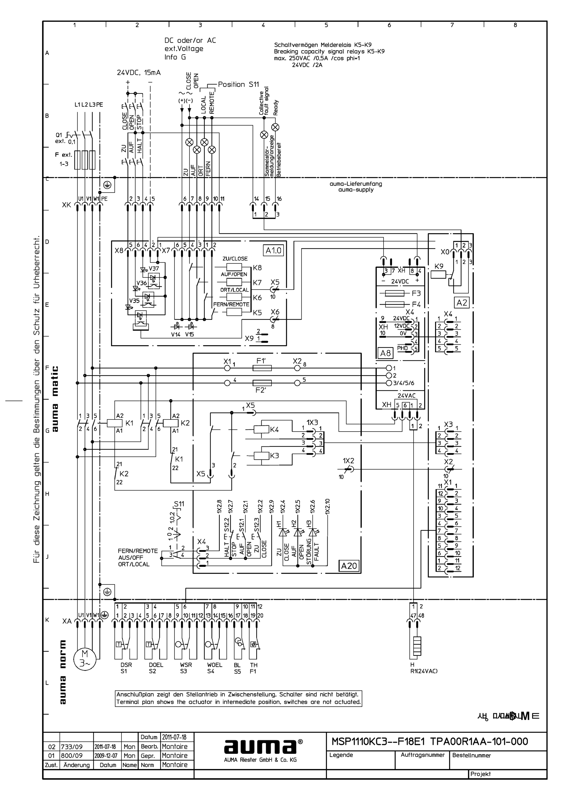
AM1: MATIC in basic version, contactors OPEN, STOP, CLOSE (24 V DC)
Wiring diagram

AM1W: MATIC with wall bracket, contactors OPEN, STOP, CLOSE (24 V DC)
Wiring diagram

AM3: MATIC in basic version and position feedback signal (0/4 - 20 mA) internally supplied, RWG in actuator,contactors OPEN, STOP, CLOSE (24 V DC)
Wiring diagram

AM4: MATIC in basic version, thyristors OPEN, STOP, CLOSE (24 V DC)
Wiring diagram

AMExC1: MATIC ExC in basic version, contactors, OPEN - STOP - CLOSE (24 V DC)
Wiring diagram

AMExC1W: MATIC ExC in basic version, wall bracket, contactors, OPEN - STOP - CLOSE (24 V DC)
Wiring diagram

AMExC2: MATIC ExC in basic version and position feedback signal (0/4 - 20 mA) internally supplied, RWG in actuator, contactors, OPEN - STOP - CLOSE (24 V DC)
Wiring diagram

AV1: AUMATIC ACV 01.2 position feedback signal 0/4 – 20 mA (potentiometer in actuator), basic version, CLOSE, OPEN, STOP, EMERGENCY (24 V DC), 6 programmable output contacts, 1-ph; 220 V - 240 V
Wiring diagram

AV1: AUMATIC ACV 01.2 position feedback signal 0/4 – 20 mA (potentiometer in actuator), basic version, CLOSE, OPEN, STOP, EMERGENCY (24 V DC), 6 programmable output contacts, 3-ph; 380 V - 480 V
Wiring diagram

AV1: AUMATIC ACV 01.2 with position feedback signal 0/4 – 20 mA (potentiometer in actuator), basic version, CLOSE, OPEN, STOP, EMERGENCY (24 V DC), 6 programmable output contacts, 3-ph; 380 V - 480 V
Wiring diagram

AV1: AUMATIC ACVExC 01.2 position feedback signal 0/4 - 20 mA (potentiometer in actuator), basic version, CLOSE, OPEN, STOP, EMERGENCY (24 V DC), 6 programmable output contacts, 1-ph; 220 V -240 V
Wiring diagram

AV1: AUMATIC ACVExC 01.2 position feedback signal 0/4 - 20 mA (potentiometer in actuator), basic version, CLOSE, OPEN, STOP, EMERGENCY (24 V DC), 6 programmable output contacts, 3-ph; 380 V - 480 V
Wiring diagram

AV1N: AUMATIC ACV 01.2 position/torque feedback signal 0/4 – 20 mA (MWG in actuator), CLOSE, OPEN, STOP, EMERGENCY (24 V DC), 6 programmable output contacts, 1-ph; 220 V - 240 V
Wiring diagram

AV1N: AUMATIC ACV 01.2 position/torque feedback signal 0/4 – 20 mA (MWG in actuator), CLOSE, OPEN, STOP, EMERGENCY (24 V DC), 6 programmable output contacts, 3-ph; 380 V - 480 V
Wiring diagram

AV1N: AUMATIC ACV 01.2 with position/torque feedback signal 0/4 – 20 mA (MWG in actuator), CLOSE, OPEN, STOP, EMERGENCY (24 V DC), 6 programmable output contacts, 3-ph; 380 V - 480 V
Wiring diagram

AV1N: AUMATIC ACVExC 01.2 position/torque feedback signal 0/4 - 20 mA (MWG in actuator), CLOSE, OPEN, STOP, EMERGENCY (24 V DC), 6 programmable output contacts, 1-ph 220 V - 240 V
Wiring diagram

AV1N: AUMATIC ACVExC 01.2 position/torque feedback signal 0/4 - 20 mA (MWG in actuator), CLOSE, OPEN, STOP, EMERGENCY (24 V DC), 6 programmable output contacts, 3-ph 380 V - 480 V
Wiring diagram

AV2: AUMATIC ACV 01.2 positioner and position feedback signal 0/4 – 20 mA (potentiometer in actuator), CLOSE, OPEN, STOP, EMERGENCY (24 V DC), 6 programmable output contacts, 1-ph; 220 V - 240 V
Wiring diagram

AV2: AUMATIC ACV 01.2 positioner and position feedback signal 0/4 – 20 mA (potentiometer in actuator), CLOSE, OPEN, STOP, EMERGENCY (24 V DC), 6 programmable output contacts, 3-ph; 380 V - 480 V
Wiring diagram

AV2: AUMATIC ACV 01.2 positioner and position/torque feedback signal 0/4 – 20 mA (MWG in actuator), MODE, CLOSE, OPEN, STOP, EMERGENCY (24 V DC), setpoint (0/4 – 20 mA), 6 programmable output contacts, 1-ph; 220 V - 240 V
Wiring diagram

AV2: AUMATIC ACV 01.2 positioner and position/torque feedback signal 0/4 – 20 mA (MWG in actuator), MODE, CLOSE, OPEN, STOP, EMERGENCY (24 V DC), setpoint (0/4 – 20 mA), 6 programmable output contacts, 3-ph; 380 V - 480 V
Wiring diagram

AV2: AUMATIC ACVExC 01.2 positioner and position feedback signal 0/4 - 20 mA (potentiometer in actuator), CLOSE, OPEN, STOP, EMERGENCY (24 V DC), 6 programmable output contacts, 1-ph; 220 V -240 V
Wiring diagram

AV2: AUMATIC ACVExC 01.2 positioner and position feedback signal 0/4 - 20 mA (potentiometer in actuator), CLOSE, OPEN, STOP, EMERGENCY (24 V DC), 6 programmable output contacts, 3-ph; 380 V - 480 V
Wiring diagram

AV2DP: AUMATIC ACV 01.2 position feedback (potentiometer in actuator), basic version, Profibus, 1-ph; 220 V - 240 V
Wiring diagram

AV2DP: AUMATIC ACV 01.2 position feedback (potentiometer in actuator), basic version, Profibus, 3-ph; 380 V - 480 V
Wiring diagram

AV2DP: AUMATIC ACVExC 01.2 position feedback (potentiometer in actuator), basic version, Profibus, 1-ph; 220 V - 240 V
Wiring diagram

AV2DP: AUMATIC ACVExC 01.2 position feedback (potentiometer in actuator), basic version, Profibus, 3-ph; 380 V - 480 V
Wiring diagram

AV2FF: AUMATIC ACV 01.2 position feedback (potentiometer in actuator), basic version, Foundation Fieldbus FF, 1-ph; 220 V - 240 V
Wiring diagram

AV2FF: AUMATIC ACV 01.2 position feedback (potentiometer in actuator), basic version, Foundation Fieldbus FF, 3-ph; 380 V - 480 V
Wiring diagram

AV2FF: AUMATIC ACVExC 01.2 position feedback (potentiometer in actuator), basic version, Foundation Fieldbus FF, 1-ph; 220 V - 240 V
Wiring diagram

AV2FF: AUMATIC ACVExC 01.2 position feedback (potentiometer in actuator), basic version, Foundation Fieldbus FF, 3-ph; 380 V - 480 V
Wiring diagram

AV2HRT: AUMATIC AC 01.2 position feedback (potentiometer in actuator), basic version, HART actuator, 1-ph; 220 V - 240 V
Wiring diagram

AV2HRT: AUMATIC AC 01.2 position feedback (potentiometer in actuator), basic version, HART actuator, 3-ph; 380 V - 480 V
Wiring diagram

AV2HRT: AUMATIC ACV 01.2 position feedback (potentiometer in actuator), basic version, HART actuator, 1-ph; 220 V - 240 V
Wiring diagram

AV2HRT: AUMATIC ACVExC 01.2 position feedback (potentiometer in actuator), basic version, HART, 1-ph; 220 V - 240 V
Wiring diagram

AV2HRT: AUMATIC ACVExC 01.2 position feedback (potentiometer in actuator), basic version, HART, 3-ph; 380 V - 480 V
Wiring diagram

AV2HRTCO: AUMATIC ACV 01.2 position feedback (potentiometer in actuator), basic version, HART Current Output, 1-ph; 220 V - 240 V
Wiring diagram

AV2HRTCO: AUMATIC ACV 01.2 position feedback (potentiometer in actuator), basic version, HART Current Output, 3-ph; 380 V- 480 V
Wiring diagram

AV2HRTCO: AUMATIC ACVExC 01.2 position feedback (potentiometer in actuator), basic version, HART Current Output, 1-ph; 220 V - 240 V
Wiring diagram

AV2HRTCO: AUMATIC ACVExC 01.2 position feedback (potentiometer in actuator), basic version, HART Current Output, 3-ph; 38 V - 480 V
Wiring diagram

AV2HRTCO: AUMATIC ACVExC 01.2 position feedback (potentiometer in actuator), basic version, HART Current Output, 3-ph; 380 V - 480 V
Wiring diagram

AV2MB: AUMATIC ACV 01.2 position feedback signal (potentiometer in actuator), basic version, Modbus, 1-ph; 220 V- 240 V
Wiring diagram

AV2MB: AUMATIC ACV 01.2 position feedback signal (potentiometer in actuator), basic version, Modbus, 3-ph; 380 V - 480 V
Wiring diagram

AV2MB: AUMATIC ACVExC 01.2 position feedback (potentiometer in actuator), basic version, Modbus RTU, 1-ph; 220 V - 240 V
Wiring diagram

AV2MB: AUMATIC ACVExC 01.2 position feedback (potentiometer in actuator), basic version, Modbus RTU, 3ph; 220 V - 240 V
Wiring diagram

AV2MB: AUMATIC ACVExC 01.2 position feedback (potentiometer in actuator), basic version, Modbus RTU, 3ph; 380 V - 480 V
Wiring diagram

AV2MBTCP: AUMATIC ACV 01.2 position feedback (potentiometer in actuator), basic version, Modbus TCP/IP, 1-ph; 220 V - 240 V
Wiring diagram

AV2MBTCP: AUMATIC ACV 01.2 position feedback (potentiometer in actuator), basic version, Modbus TCP/IP, 3-ph; 380 V - 480 V
Wiring diagram

AV2MBTCP: AUMATIC ACVExC 01.2 position feedback (ptentiometer in actuator), basic version Modbus TCP/IP, 1-ph; 220 V - 240 V
Wiring diagram

AV2MBTCP: AUMATIC ACVExC 01.2 position feedback (ptentiometer in actuator), basic version Modbus TCP/IP, 3-ph; 380 V - 480 V
Wiring diagram

AV2N: AUMATIC ACVExC 01.2 positioner and position/torque feedback signal 0/4 - 20 mA (MWG in actuator), MODE, CLOSE, OPEN, STOP, EMERGENCY (24 V DC), setpoint (0/4 - 20 mA), 6 programmable output contacts, 1-ph 220 V - 240 V
Wiring diagram

AV2N: AUMATIC ACVExC 01.2 positioner and position/torque feedback signal 0/4 - 20 mA (MWG in actuator), MODE, CLOSE, OPEN, STOP, EMERGENCY (24 V DC), setpoint (0/4 - 20 mA), 6 programmable output contacts, 3-ph 380 V - 480 V
Wiring diagram

AV2NDP: AUMATIC ACV 01.2 position/torque feedback (MWG in actuator), Profibus, 1-ph; 220 V - 240 V
Wiring diagram

AV2NDP: AUMATIC ACV 01.2 position/torque feedback (MWG in actuator), Profibus, 3-ph; 380 V - 480 V
Wiring diagram

AV2NDP: AUMATIC ACVExC 01.2 position/torque feedback (MWG in actuator), Profibus, 1-ph; 220 V - 240 V
Wiring diagram

AV2NDP: AUMATIC ACVExC 01.2 position/torque feedback (MWG in actuator), Profibus, 3-ph; 380 V - 480 V
Wiring diagram

AV2NFF: AUMATIC ACV 01.2 position feedback/torque signal (potentiometer in actuator), Foundation Fieldbus FF, 1 ph; 220 V - 240 V
Wiring diagram

AV2NFF: AUMATIC ACV 01.2 position feedback/torque signal (potentiometer in actuator), Foundation Fieldbus FF, 3 ph; 380 V - 480 V
Wiring diagram

AV2NFF: AUMATIC ACVExC 01.2 position/torque feedback (MWG in actuator), Foundation Fieldbus FF, 1-ph; 220 V - 480 V
Wiring diagram

AV2NFF: AUMATIC ACVExC 01.2 position/torque feedback (MWG in actuator), Foundation Fieldbus FF, 3-ph; 380 V - 480 V
Wiring diagram

AV2NHRT: AUMATIC AC 01.2 position/torque feedback (MWG in actuator), HART actuator, 3-ph; 380 V - 480 V
Wiring diagram

AV2NHRT: AUMATIC ACV 01.2 position/torque feedback (MWG in actuator), HART actuator, 1-ph; 220 V - 240 V
Wiring diagram

AV2NHRT: AUMATIC ACVExC 01.2 position/torque feedback (MWG in actuator), HART, 1-ph; 220 V - 240 V
Wiring diagram

AV2NHRT: AUMATIC ACVExC 01.2 position/torque feedback (MWG in actuator), HART, 3-ph; 380 V - 480 V
Wiring diagram

AV2NHRTCO: AUMATIC ACV 01.2 position/torque feedback (MWG in actuator), HART Current Output, 1-ph; 220 V - 240 V
Wiring diagram

AV2NHRTCO: AUMATIC ACV 01.2 position/torque feedback (MWG in actuator), HART Current Output, 3-ph; 380 V - 480 V
Wiring diagram

AV2NHRTCO: AUMATIC ACVExC 01.2 position/torque feedback (MWG in actuator), HART Current Output, 1-ph; 220 V - 240 V
Wiring diagram

AV2NHRTCO: AUMATIC ACVExC 01.2 position/torque feedback (MWG in actuator), HART Current Output, 3-ph; 380 V - 480 V
Wiring diagram

AV2NMB: AUMATIC ACV 01.2 position/torque feedback (MWG in actuator), Modbus, 1-ph; 220 V- 240 V
Wiring diagram

AV2NMB: AUMATIC ACV 01.2 position/torque feedback (MWG in actuator), Modbus, 3-ph; 380 V - 480 V
Wiring diagram

AV2NMB: AUMATIC ACVExC 01.2 position/torque feedback (MWG in actuator), Modbus RTU, 1-ph; 220 V - 240 V
Wiring diagram

AV2NMB: AUMATIC ACVExC 01.2 position/torque feedback (MWG in actuator), Modbus RTU, 3-ph; 380 V - 480 V
Wiring diagram

AV2NMBTCP: AUMATIC ACV 01.2 position/torque feedback (MWG in actuator), Modbus TCP/IP, 1-ph; 220 V - 240 V
Wiring diagram

AV2NMBTCP: AUMATIC ACV 01.2 position/torque feedback (MWG in actuator), Modbus TCP/IP, 3-ph; 380 V - 480 V
Wiring diagram

AV2NMBTCP: AUMATIC ACVExC 01.2 position/torque feedback (MWG in actuator), Modbus TCP/IP, 1-ph; 220 V - 240 V
Wiring diagram

AV2NMBTCP: AUMATIC ACVExC 01.2 position/torque feedback (MWG in actuator), Modbus TCP/IP, 3-ph; 380 V - 480 V
Wiring diagram

AV2NPN: AUMATIC ACV 01.2 position/torque feedback (MWG in actuator), Profinet, 1-ph; 220 V - 240 V
Wiring diagram

AV2NPN: AUMATIC ACV 01.2 position/torque feedback (MWG in actuator), Profinet, 3-ph; 380 V - 480 V
Wiring diagram

AV2PN: AUMATIC ACV 01.2 position feedback (potentiometer in actuator), Profinet, 1-ph; 220 V - 240 V
Wiring diagram

AV2PN: AUMATIC ACV 01.2 position feedback (potentiometer in actuator), Profinet, 3-ph; 380 V - 480 V
Wiring diagram

AV4DP: AUMATIC ACV 01.2 positioner and position feedback signal 0/4 – 20 mA (potentiometer in actuator), basic version, MODE, CLOSE, OPEN, STOP, EMERGENCY, I/O (24 V DC), 6 programmable output contacts, Profibus, 1-ph; 220 V - 240 V
Wiring diagram

AV4DP: AUMATIC ACV 01.2 positioner and position feedback signal 0/4 – 20 mA (potentiometer in actuator), basic version, MODE, CLOSE, OPEN, STOP, EMERGENCY, I/O (24 V DC), 6 programmable output contacts, Profibus, 3-ph; 380 V - 480 V
Wiring diagram

AV4DP: AUMATIC ACVExC 01.2 positioner und position feedback signal 0/4 - 20 mA (potentiometer in actuator), basic version, MODE, CLOSE, OPEN, STOP, EMERGENCY, I/O ( 24 V DC), 6 programmable output contacts, Profibus DP, 1-ph; 220 V - 240 V
Wiring diagram

AV4DP: AUMATIC ACVExC 01.2 positioner und position feedback signal 0/4 - 20 mA (potentiometer in actuator), basic version, MODE, CLOSE, OPEN, STOP, EMERGENCY, I/O ( 24 V DC), 6 programmable output contacts, Profibus DP, 3-ph; 380 V - 480 V
Wiring diagram

AV4FF: AUMATIC ACExC 01.2 positioner and position feedback signal 0/4 - 20 mA (potentiometer in actuator), basic version, MODE, CLOSE, OPEN, STOP, EMERGENCY, I/O ( 24 V DC), 6 programmable output contacts, Foundation Fieldbus FF, 1-ph; 220 V - 240 V
Wiring diagram

AV4FF: AUMATIC ACExC 01.2 positioner and position feedback signal 0/4 - 20 mA (potentiometer in actuator), basic version, MODE, CLOSE, OPEN, STOP, EMERGENCY, I/O ( 24 V DC), 6 programmable output contacts, Foundation Fieldbus FF, 3-ph; 380 V - 480 V
Wiring diagram

AV4FF: AUMATIC ACV 01.2 positioner and position feedback signal 0/4 – 20 mA (potentiometer in actuator), basic version, MODE, CLOSE, OPEN, STOP, EMERGENCY, I/O (24 V DC), 6 programmable output contacts, Foundation Fieldbus, 1-ph; 220 V - 240 V
Wiring diagram

AV4FF: AUMATIC ACV 01.2 positioner and position feedback signal 0/4 – 20 mA (potentiometer in actuator), basic version, MODE, CLOSE, OPEN, STOP, EMERGENCY, I/O (24 V DC), 6 programmable output contacts, Foundation Fieldbus, 3-ph; 380 V - 480 V
Wiring diagram

AV4HRT: AUMATIC ACV 01.2 positioner and position feedback signal 0/4 – 20 mA (potentiometer in actuator), basic version, MODE, CLOSE, OPEN, STOP, EMERGENCY, I/O (24 V DC), 6 programmable output contacts, HART, 1-ph; 220 V - 240 V
Wiring diagram

AV4HRT: AUMATIC ACV 01.2 positioner and position feedback signal 0/4 – 20 mA (potentiometer in actuator), basic version, MODE, CLOSE, OPEN, STOP, EMERGENCY, I/O (24 V DC), 6 programmable output contacts, HART, 3-ph; 380 V - 480 V
Wiring diagram

AV4HRT: AUMATIC ACVExC 01.2 positioner and position feedback signal 0/4 - 20 mA (potentiometer in actuator), basic version, MODE, CLOSE, OPEN, STOP, EMERGENCY; I/O (24 V DC), 6 programmable output contacts, HART, 1-ph; 220 V - 240 V
Wiring diagram

AV4HRT: AUMATIC ACVExC 01.2 positioner and position feedback signal 0/4 - 20 mA (potentiometer in actuator), basic version, MODE, CLOSE, OPEN, STOP, EMERGENCY; I/O (24 V DC), 6 programmable output contacts, HART, 3-ph; 380 V - 480 V
Wiring diagram

AV4HRTCO: AUMATIC ACV 01.2 positioner and position feedback signal 0/4 – 20 mA (potentiometer in actuator), basic version, MODE, CLOSE, OPEN, STOP, EMERGENCY, I/O (24 V DC), 6 programmable output contacts, HART, 1-ph; 220 V - 240 V
Wiring diagram

AV4HRTCO: AUMATIC ACV 01.2 positioner and position feedback signal 0/4 – 20 mA (potentiometer in actuator), basic version, MODE, CLOSE, OPEN, STOP, EMERGENCY, I/O (24 V DC), 6 programmable output contacts, HART, 3-ph; 380 V - 480 V
Wiring diagram

AV4HRTCO: AUMATIC ACVExC 01.2 positioner and position feedback signal 0/4 - 20 mA (potentiometer in actuator), basic version, MODE, CLOSE, OPEN, STOP, EMERGENCY, I/O (24 V DC), 6 programmable output contacts, HART Current output, 1-ph; 220 V - 240 V
Wiring diagram

AV4HRTCO: AUMATIC ACVExC 01.2 positioner and position feedback signal 0/4 - 20 mA (potentiometer in actuator), basic version, MODE, CLOSE, OPEN, STOP, EMERGENCY, I/O (24 V DC), 6 programmable output contacts, HART Current output, 3-ph; 380 V - 480 V
Wiring diagram

AV4MB: AUMATIC ACV 01.2 positioner and position feedback signal 0/4 – 20 mA (potentiometer in actuator), basic version, MODE, CLOSE, OPEN, STOP, EMERGENCY, I/O (24 V DC), 6 programmable output contacts, Modbus, 1-ph; 220 V - 240 V
Wiring diagram

AV4MB: AUMATIC ACV 01.2 positioner and position feedback signal 0/4 – 20 mA (potentiometer in actuator), basic version, MODE, CLOSE, OPEN, STOP, EMERGENCY, I/O (24 V DC), 6 programmable output contacts, Modbus, 3-ph; 380 V - 480 V
Wiring diagram

AV4MB: AUMATIC ACVExC 01.2 positionier and position feedback signal 0/4 - 20 mA (potentiometer in actuator), basic version, MODE, CLOSE, OPEN, STOP, EMERGENCY, I/O (24 V DC), 6 programmable output contacts, Modbus RTU, 1-ph; 220 V - 240 V
Wiring diagram

AV4MB: AUMATIC ACVExC 01.2 positionier and position feedback signal 0/4 - 20 mA (potentiometer in actuator), basic version, MODE, CLOSE, OPEN, STOP, EMERGENCY, I/O (24 V DC), 6 programmable output contacts, Modbus RTU, 3-ph; 380 V - 480 V
Wiring diagram

AV4MBTCP: AUMATIC ACV 01.2 positioner and position feedback signal 0/4 – 20 mA (potentiometer in actuator), basic version, MODE, CLOSE, OPEN, STOP, EMERGENCY, I/O (24 V DC), 6 programmable output contacts, Modbus TCP/IP, 1-ph; 220 V - 240 V
Wiring diagram

AV4MBTCP: AUMATIC ACV 01.2 positioner and position feedback signal 0/4 – 20 mA (potentiometer in actuator), basic version, MODE, CLOSE, OPEN, STOP, EMERGENCY, I/O (24 V DC), 6 programmable output contacts, Modbus TCP/IP, 3-ph; 380 V - 480 V
Wiring diagram

AV4MBTCP: AUMATIC ACVExC 01.2 positioner and position feedbak signal 0/4 - 20 mA (potentiometer in actuator), basic version, MODE, CLOSE, OPEN, STOP, EMERGENCY, I/O (24 V DC), 6 programmable output contacts, Modbus TCP/IP 1-ph; 220 V - 240 V
Wiring diagram

AV4MBTCP: AUMATIC ACVExC 01.2 positioner and position feedbak signal 0/4 - 20 mA (potentiometer in actuator), basic version, MODE, CLOSE, OPEN, STOP, EMERGENCY, I/O (24 V DC), 6 programmable output contacts, Modbus TCP/IP 3-ph; 380 V - 480 V
Wiring diagram

AV4NDP: AUMATIC ACV 01.2 positioner and position/torque feedback signal 0/4 – 20 mA (MWG in actuator), MODE, CLOSE, OPEN, STOP, EMERGENCY, I/O (24 V DC), 6 programmable output contacts, Profibus DP, 1-ph; 220 V - 240 V
Wiring diagram

AV4NDP: AUMATIC ACV 01.2 positioner and position/torque feedback signal 0/4 – 20 mA (MWG in actuator), MODE, CLOSE, OPEN, STOP, EMERGENCY, I/O (24 V DC), 6 programmable output contacts, Profibus DP, 3-ph; 380 V - 480 V
Wiring diagram

AV4NDP: AUMATIC ACVExC 01.2 positioner and position/torque feedback signal 0/4 - 20 mA (MWG in actuator), MODE, CLOSE, OPEN, STOP, EMERGENCY, I/O (24 V DC), 6 programmable output contacts, Profibus DP, 1-ph; 220 V - 240 V
Wiring diagram

AV4NDP: AUMATIC ACVExC 01.2 positioner and position/torque feedback signal 0/4 - 20 mA (MWG in actuator), MODE, CLOSE, OPEN, STOP, EMERGENCY, I/O (24 V DC), 6 programmable output contacts, Profibus DP, 3-ph; 380 V - 480 V
Wiring diagram

AV4NFF: AUMATIC ACV 01.2 positioner and position/torque feedback signal 0/4 – 20 mA (MWG in actuator), MODE, CLOSE, OPEN, STOP, EMERGENCY, I/O (24 V DC), 6 programmable output contacts, Foundation Fieldbus FF, 1-ph; 220 V - 240 V
Wiring diagram

AV4NFF: AUMATIC ACV 01.2 positioner and position/torque feedback signal 0/4 – 20 mA (MWG in actuator), MODE, CLOSE, OPEN, STOP, EMERGENCY, I/O (24 V DC), 6 programmable output contacts, Foundation Fieldbus FF, 3-ph; 380 V - 480 V
Wiring diagram

AV4NFF: AUMATIC ACVExC 01.2 positioner and position/torque feedback signal 0/4 - 20 mA (MWG in actuator), MODE, CLOSE, OPEN, STOP, EMERGENCY, I/O (224 V DC), 6 programmable output contacts, Foundation Fieldbus FF, 1-ph; 220 V - 240 V
Wiring diagram

AV4NFF: AUMATIC ACVExC 01.2 positioner and position/torque feedback signal 0/4 - 20 mA (MWG in actuator), MODE, CLOSE, OPEN, STOP, EMERGENCY, I/O (224 V DC), 6 programmable output contacts, Foundation Fieldbus FF, 3-ph; 380 V - 480 V
Wiring diagram

AV4NHRT: AUMATIC ACVExC 01.2 positioner and position/torque feedback signal 0/4 - 20 mA (MWG in actuator), MODE, CLOSE, OPEN, STOP, EMERGENCY, I/O ( 24 V DC), 6 programmable output contacts, HART, 1-ph; 220 V - 240 V
Wiring diagram

AV4NHRT: AUMATIC ACVExC 01.2 positioner and position/torque feedback signal 0/4 - 20 mA (MWG in actuator), MODE, CLOSE, OPEN, STOP, EMERGENCY, I/O ( 24 V DC), 6 programmable output contacts, HART, 3-ph; 380 V - 480 V
Wiring diagram

AV4NHRTCO: AUMATIC ACVExC 01.2 position/torque feedback (MWG in acutator), MODE, CLOSE, OPEN, STOP, EMERGENCY, I/O (24 V DC), 6 programmabel output contacts, HART Current output, 1-ph; 220 V - 240 V
Wiring diagram

AV4NHRTCO: AUMATIC ACVExC 01.2 position/torque feedback (MWG in acutator), MODE, CLOSE, OPEN, STOP, EMERGENCY, I/O (24 V DC), 6 programmabel output contacts, HART Current output, 3-ph; 380 V - 480 V
Wiring diagram

AV4NMB: AUMATIC ACV 01.2 positioner and position/torque feedback signal 0/4 – 20 mA (MWG in actuator), MODE, CLOSE, OPEN, STOP, EMERGENCY, I/O (24 V DC), 6 programmable output contacts, Modbus RTU, 1-ph; 220 V - 240 V
Wiring diagram

AV4NMB: AUMATIC ACV 01.2 positioner and position/torque feedback signal 0/4 – 20 mA (MWG in actuator), MODE, CLOSE, OPEN, STOP, EMERGENCY, I/O (24 V DC), 6 programmable output contacts, Modbus RTU, 3-ph; 380 V - 480 V
Wiring diagram

AV4NMB: AUMATIC ACVExC 01.2 positioner and position/torque feedback signal 0/4 - 20 mA (MWG in actuator), MODE, CLOSE, OPEN, STOP, EMERGENCY, I/O (24 V DC), 6 programmable output contacts, Modbus RTU, 1-ph; 220 V - 240 V
Wiring diagram

AV4NMB: AUMATIC ACVExC 01.2 positioner and position/torque feedback signal 0/4 - 20 mA (MWG in actuator), MODE, CLOSE, OPEN, STOP, EMERGENCY, I/O (24 V DC), 6 programmable output contacts, Modbus RTU, 3-ph; 380 V - 480 V
Wiring diagram

AV4NMBTCP: AUMATIC ACV 01.2 positioner and position/torque feedback signal 0/4 – 20 mA (MWG in actuator), MODE, CLOSE, OPEN, STOP, EMERGENCY, I/O (24 V DC), 6 programmable output contacts, Modbus TCP/IP, 1-ph; 220 V - 240 V
Wiring diagram

AV4NMBTCP: AUMATIC ACV 01.2 positioner and position/torque feedback signal 0/4 – 20 mA (MWG in actuator), MODE, CLOSE, OPEN, STOP, EMERGENCY, I/O (24 V DC), 6 programmable output contacts, Modbus TCP/IP, 3-ph; 380 V - 480 V
Wiring diagram

AV4NMBTCP: AUMATIC ACVExC 01.2 positioner and position/torque feedback signal 0/4 - 20 mA (MWG in actuator), MODE, CLOSE, OPEN, STOP, EMERGENCY, I/O (24 V DC), 6 programmable output contacts, Modbus TCP/IP, 1-ph; 220 V - 240 V
Wiring diagram

AV4NMBTCP: AUMATIC ACVExC 01.2 positioner and position/torque feedback signal 0/4 - 20 mA (MWG in actuator), MODE, CLOSE, OPEN, STOP, EMERGENCY, I/O (24 V DC), 6 programmable output contacts, Modbus TCP/IP, 3-ph; 380 V - 480 V
Wiring diagram

AV4NPN: AUMATIC ACV 01.2 positioner and position/torque feedback signal 0/4 – 20 mA (MWG in actuator),Profinet, 1-ph; 220 V - 240 V
Wiring diagram

AV4NPN: AUMATIC ACV 01.2 positioner and position/torque feedback signal 0/4 – 20 mA (MWG in actuator),Profinet, 3-ph; 380 V - 480 V
Wiring diagram

AV4PN: ACV 01.2 positioner and position feedback signal 0/4 – 20 mA (potentiometer in actuator), Profinet,1-ph; 220 V - 240 V
Wiring diagram

AV4PN: AUMATIC ACV 01.2 positioner and position feedback signal 0/4 – 20 mA (potentiometer in actuator), Profinet, 3-ph; 380 V - 480 V
Wiring diagram

AV4PN: AUMATIC ACV 01.2 positioner and position feedback signal 0/4 – 20 mA (potentiometer in actuator), Profinet,1-ph; 220 V - 240 V
Wiring diagram

AV5N: AUMATIC ACV 01.2 position/torque feedback signal 0/4 – 20 mA (MWG in actuator), CLOSE, OPEN, STOP, EMERGENCY, INTERLOCK CLOSE, INTERLOCK OPEN, 6 programmable output contacts, 1-ph; 220 V - 240 V
Wiring diagram

AV5N: AUMATIC ACV 01.2 position/torque feedback signal 0/4 – 20 mA (MWG in actuator), CLOSE, OPEN, STOP, EMERGENCY, INTERLOCK CLOSE, INTERLOCK OPEN, 6 programmable output contacts, 3-ph; 380 V - 480 V
Wiring diagram

AV5N: AUMATIC ACVExC 01.2 position/torque feedback signal 0/4 - 20 mA (MWG in actuator), CLOSE, OPEN, STOP, EMERGENCY INTERLOCK CLOSE, INTERLOCK OPEN, 6 programmable output contacts, 1-ph 220 V - 240 V
Wiring diagram

AV5N: AUMATIC ACVExC 01.2 position/torque feedback signal 0/4 - 20 mA (MWG in actuator), CLOSE, OPEN, STOP, EMERGENCY INTERLOCK CLOSE, INTERLOCK OPEN, 6 programmable output contacts, 3-ph 380 V - 480 V
Wiring diagram

AVN4HRT: AUMATIC ACV 01.2 positioner and position/torque feedback signal 0/4 – 20 mA (MWG in actuator), MODE, CLOSE, OPEN, STOP, EMERGENCY, I/O (24 V DC), 6 programmable output contacts, HART, 1-ph; 220 V - 240 V
Wiring diagram

AVN4HRT: AUMATIC ACV 01.2 positioner and position/torque feedback signal 0/4 – 20 mA (MWG in actuator), MODE, CLOSE, OPEN, STOP, EMERGENCY, I/O (24 V DC), 6 programmable output contacts, HART, 3-ph; 380 V - 480 V
Wiring diagram

AVN4HRTCO: AUMATIC ACV 01.2 position/torque feedback (MWG in actuator), MODE, CLOSE, OPEN, STOP, EMERGENCY, I/O (24 V DC), 6 programmable output contacts, HART Current Output, 1-ph; 220 V - 240 V
Wiring diagram

AVN4HRTCO: AUMATIC ACV 01.2 position/torque feedback (MWG in actuator), MODE, CLOSE, OPEN, STOP, EMERGENCY, I/O (24 V DC), 6 programmable output contacts, HART Current Output, 3-ph; 380 V - 480 V
Wiring diagram

Frequent wiring diagrams, Multi-turn actuators SA 07.1 - 48.1, Part-turn actuators SG 05.1 - 12.1
Wiring diagram
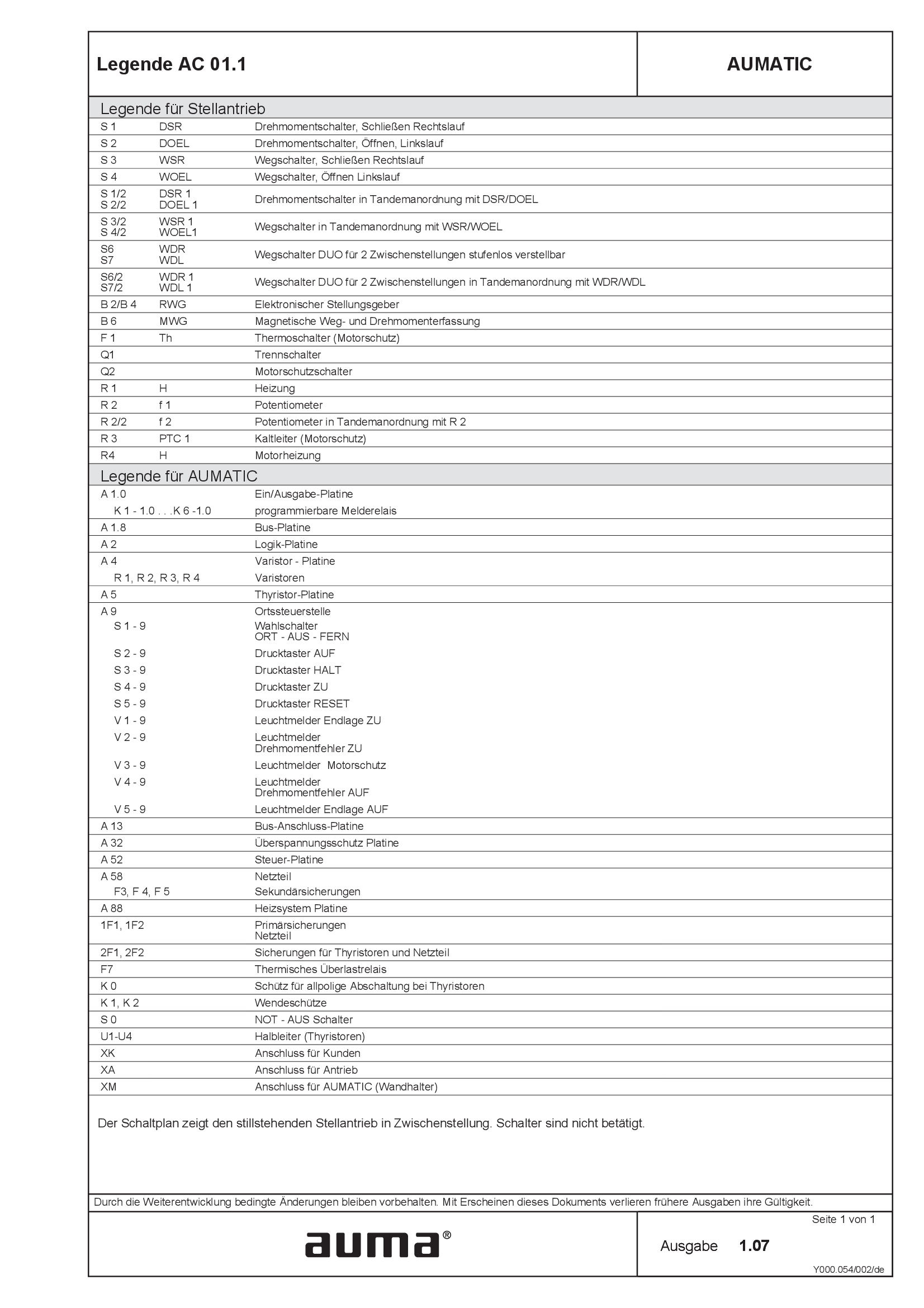
Legend AC 01.1
Wiring diagram
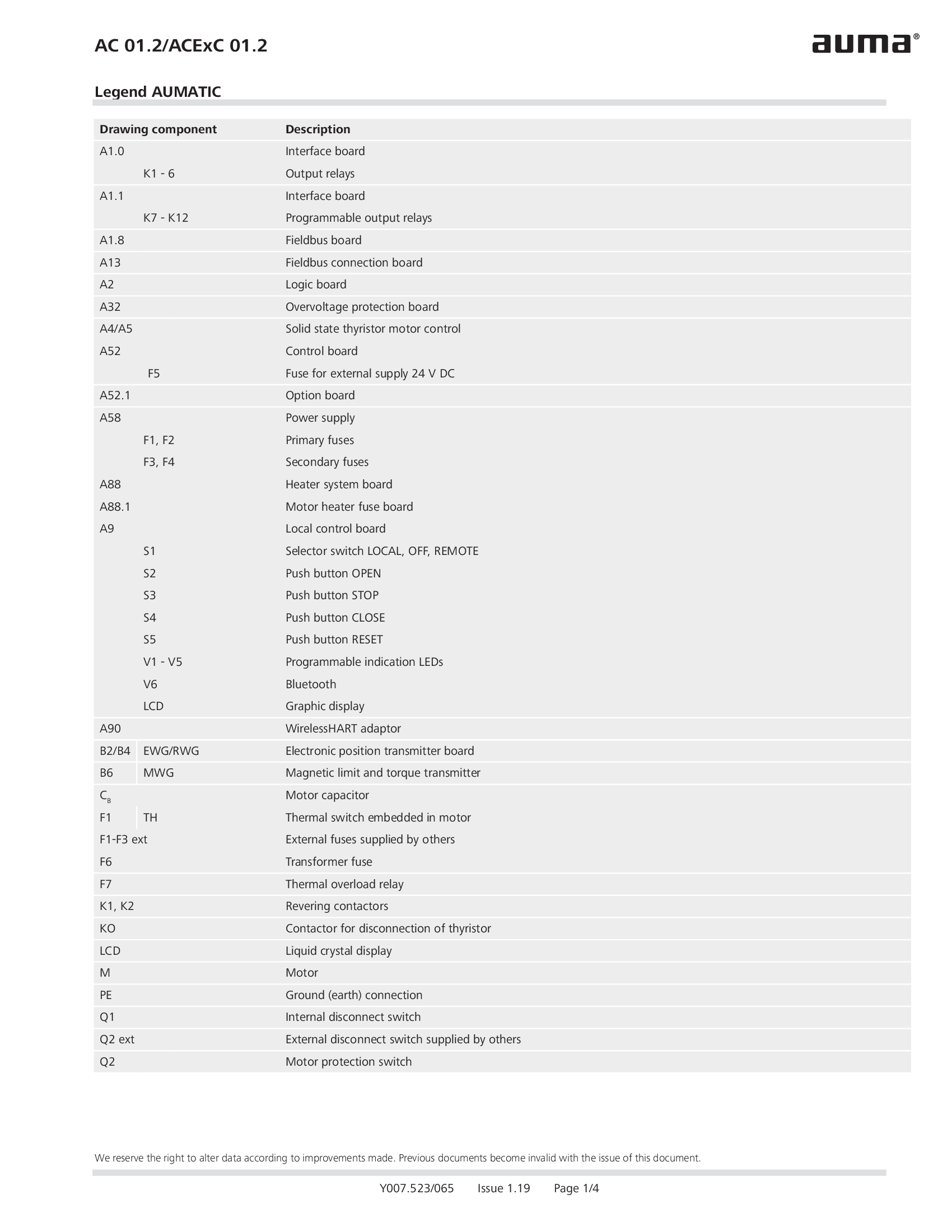
Legend AC 01.2/ACEx 01.2
Wiring diagram

Legend AC 01.2/ACEx 01.2, AC 01.2-SIL/ACExC 01.2-SIL
Wiring diagram
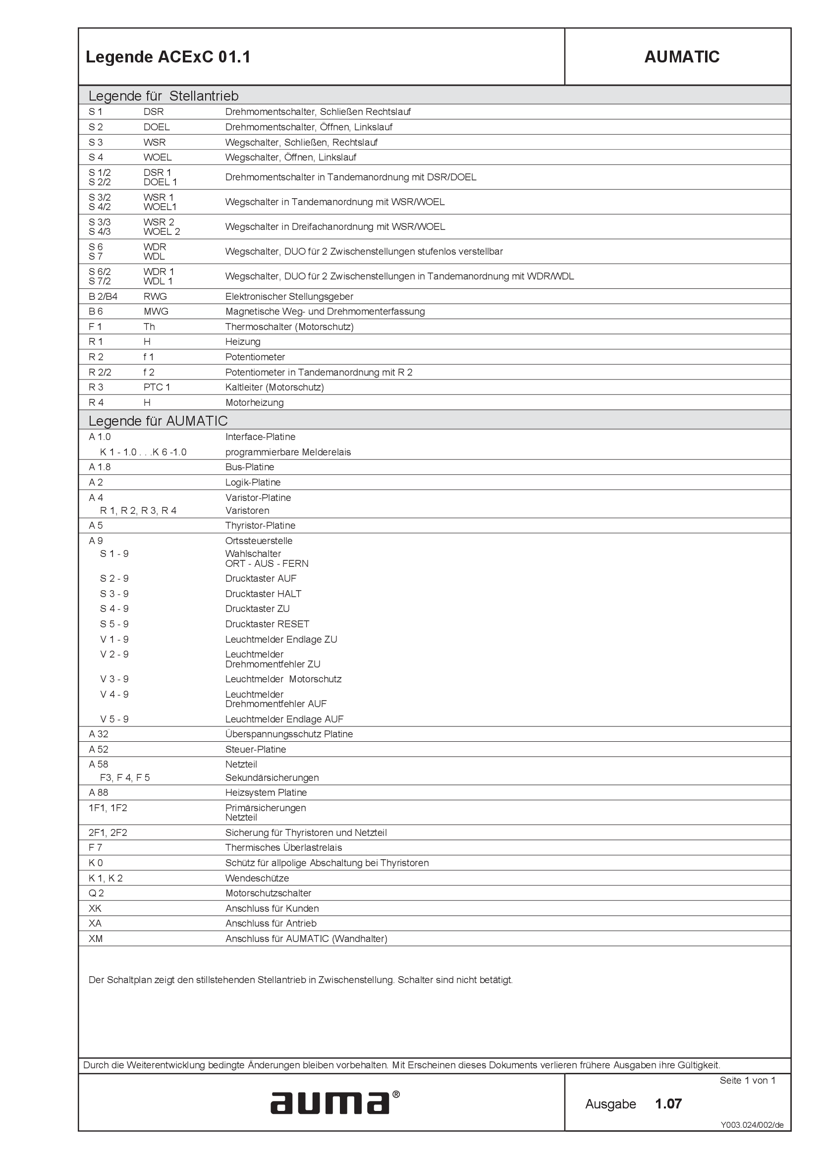
Legend ACExC01.1
Wiring diagram
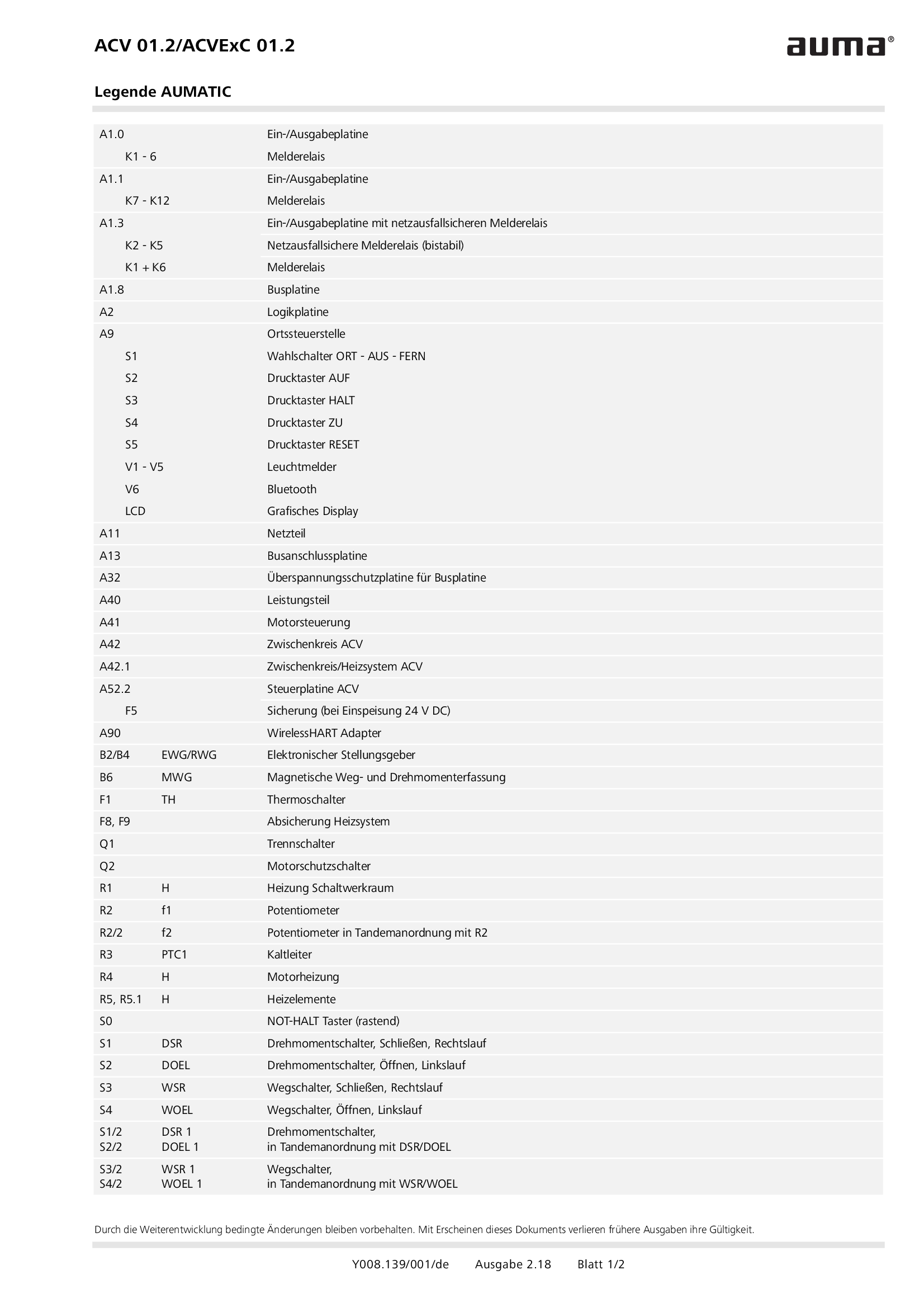
Legend ACV 01.2/ACVEx 01.2
Wiring diagram
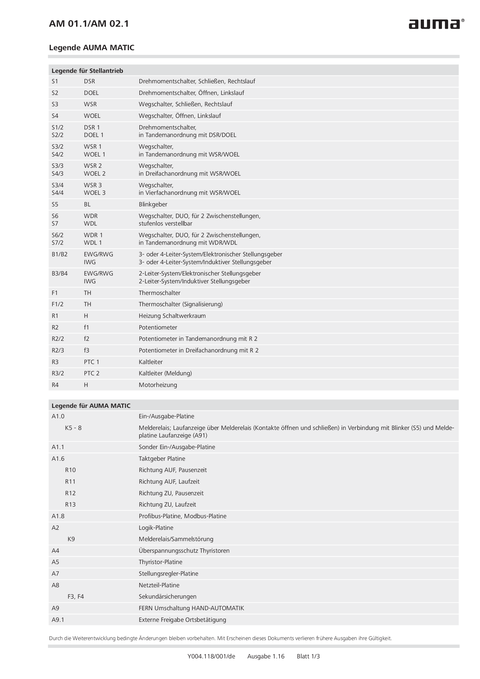
Legend AM 01.1/AM 02.1
Wiring diagram
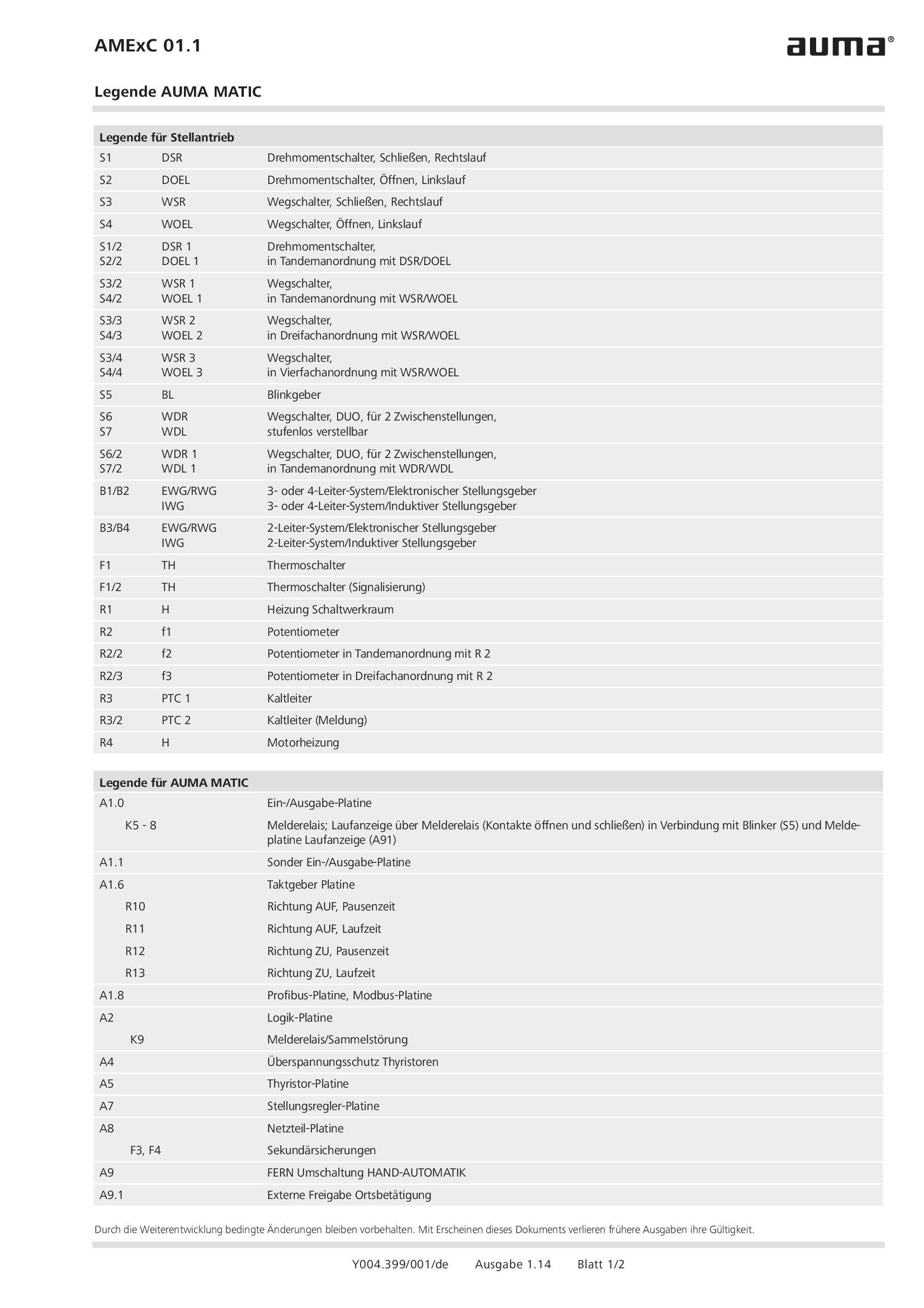
Legend AMExC 01.1
Wiring diagram

Legend SGC/SVC
Wiring diagram
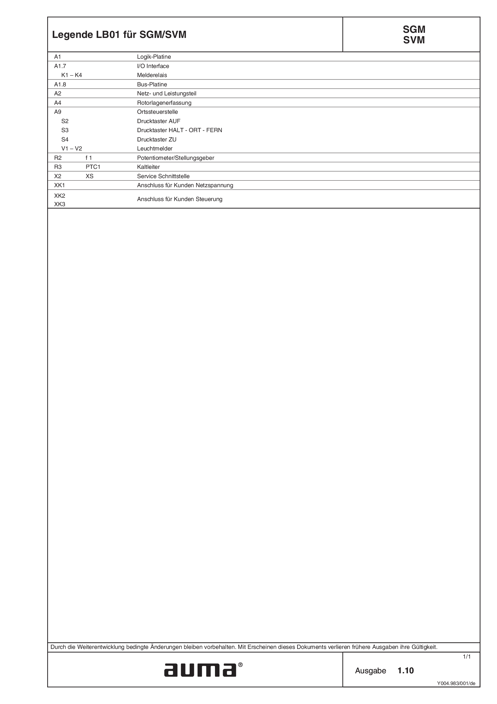
Legend SGM/SVM
Wiring diagram
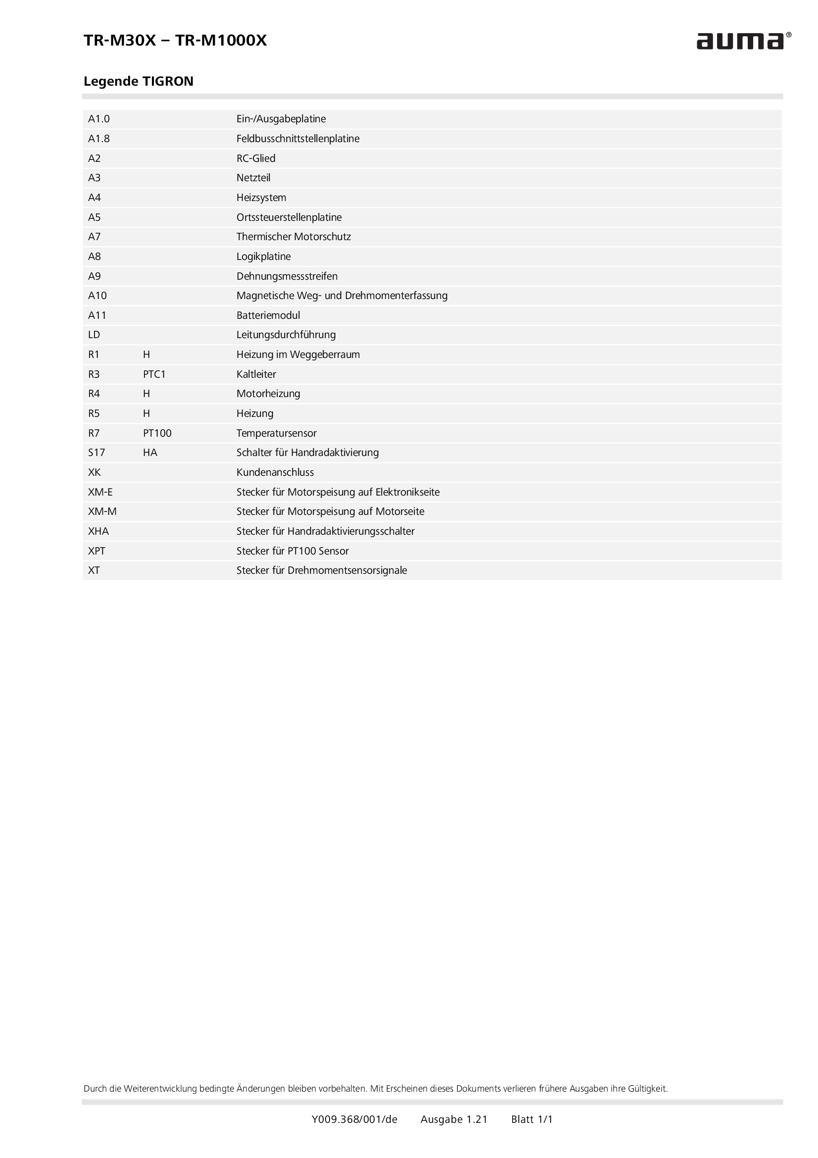
Legend TR-M30X – TR-M1000X
Wiring diagram
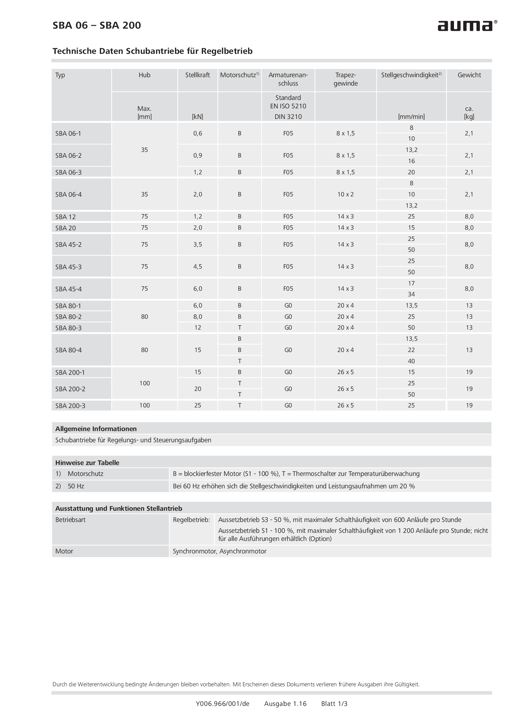
Linear actuators SBA 06 - 200 for modulating duty
Wiring diagram
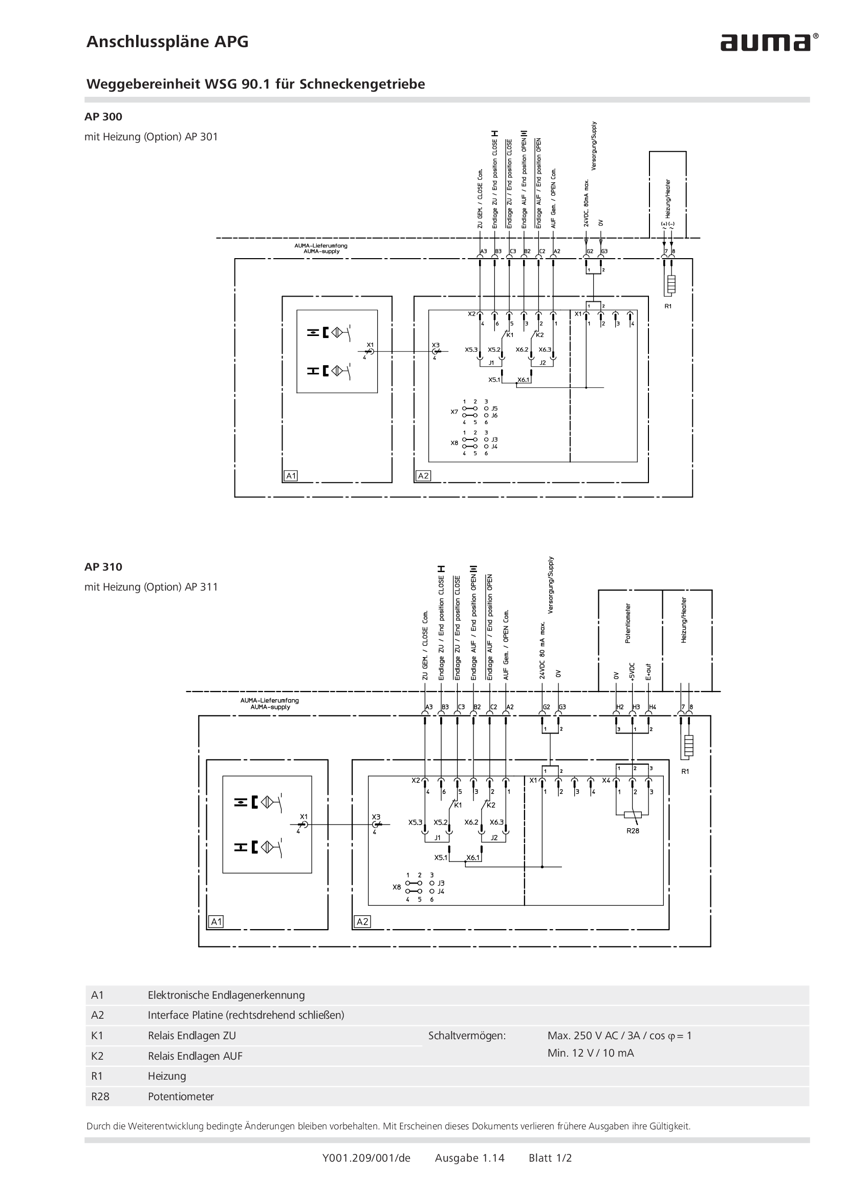
Overview terminal plans APG Valve position indicator WSG 90.1 for worm gearboxes
Wiring diagram
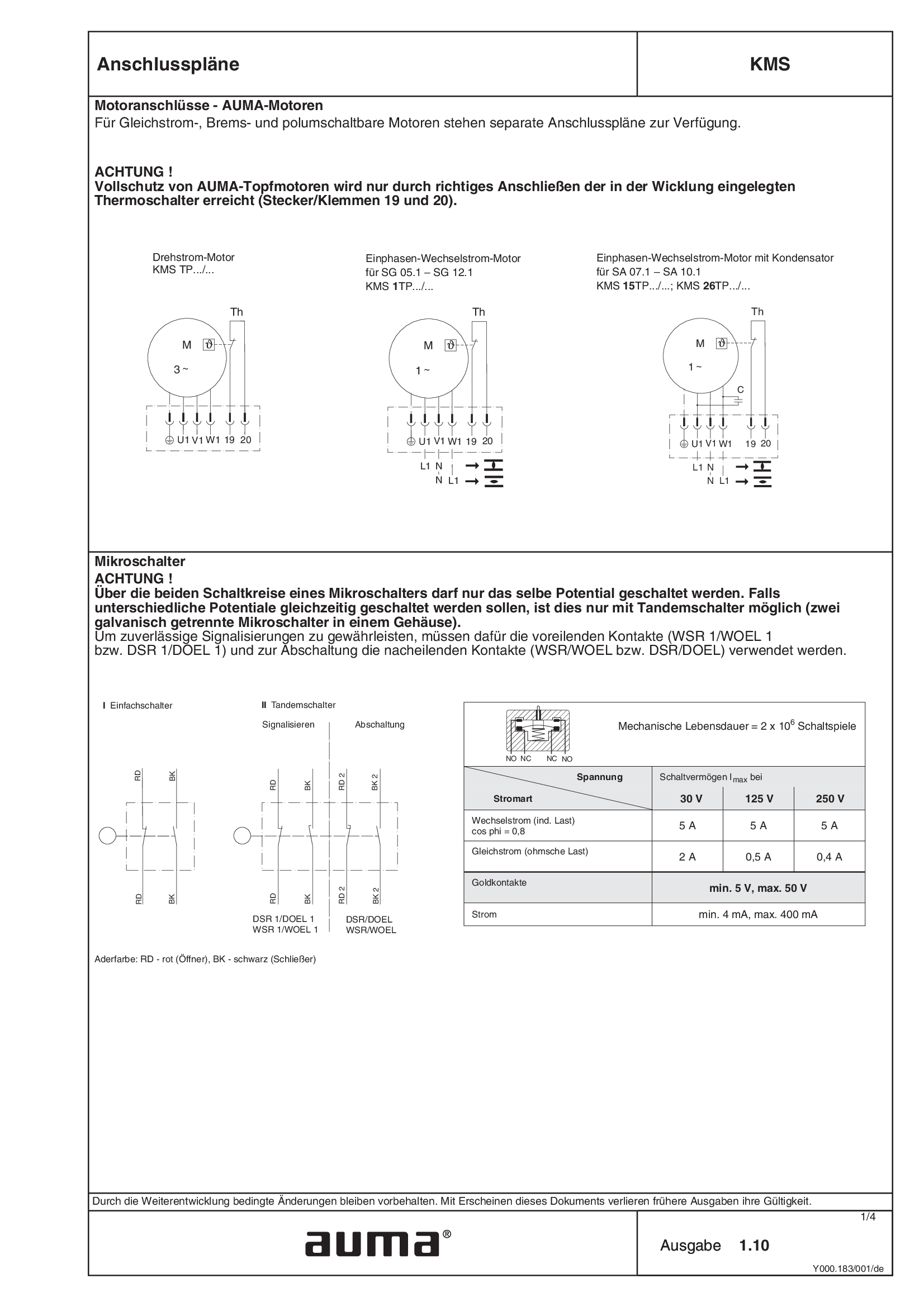
Overview terminal plans KMS
Wiring diagram
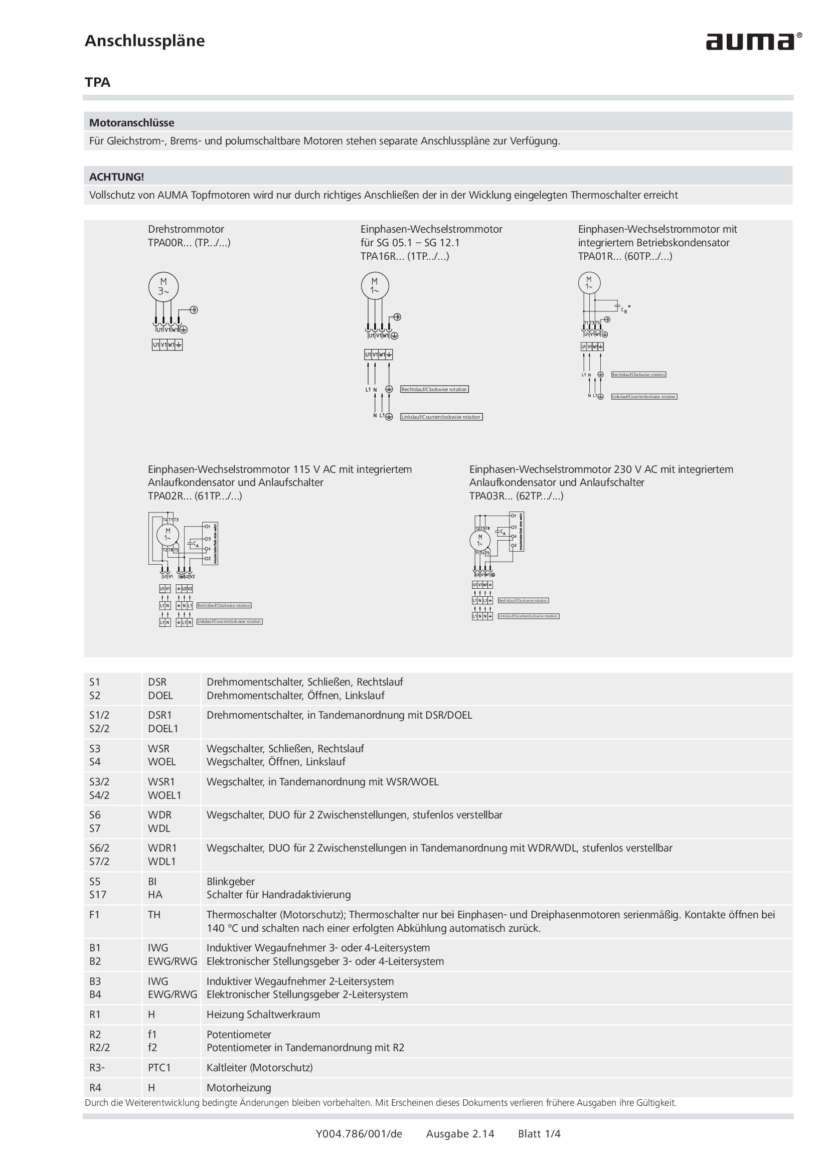
Overview terminal plans TPA
Wiring diagram

PROFOX PF-Q, PF-M, Modbus RTU
Wiring diagram

PROFOX PF-Q, PF-M, Profibus DP, with analogue input
Wiring diagram

PROFOX PF-Q, PF-M, Profibus DP, without analogue input
Wiring diagram

PROFOX PF-Q, PF-M, Profibus DP, without analogue input, direct current, 24 V DC
Wiring diagram

PROFOX PF-Q, PF-M, with analogue input
Wiring diagram

PROFOX PF-Q, PF-M, with analogue input, direct current, 24 V DC
Wiring diagram

PROFOX PF-Q, PF-M, without analogue input
Wiring diagram
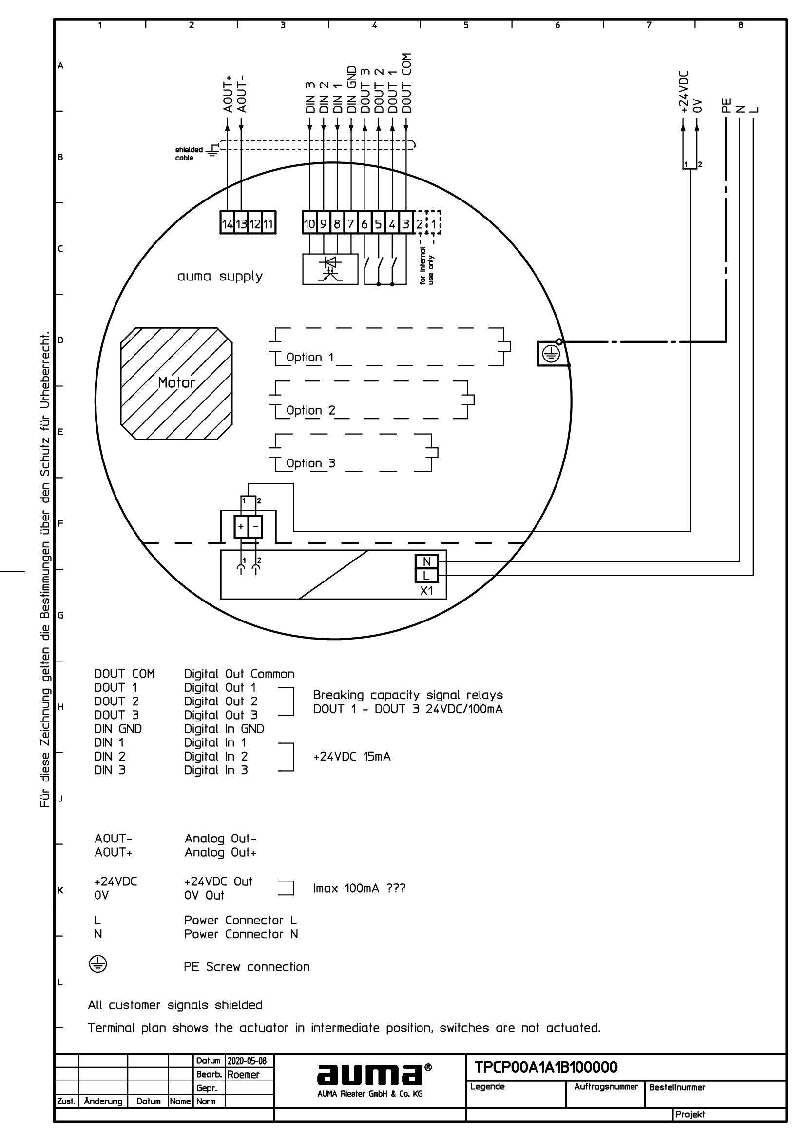
PROFOX PF-Q, PF-M, without analogue input, 24 V DC auxiliary voltage
Wiring diagram

PROFOX PF-Q, PF-M, without analogue input, direct current, 24 V DC
Wiring diagram
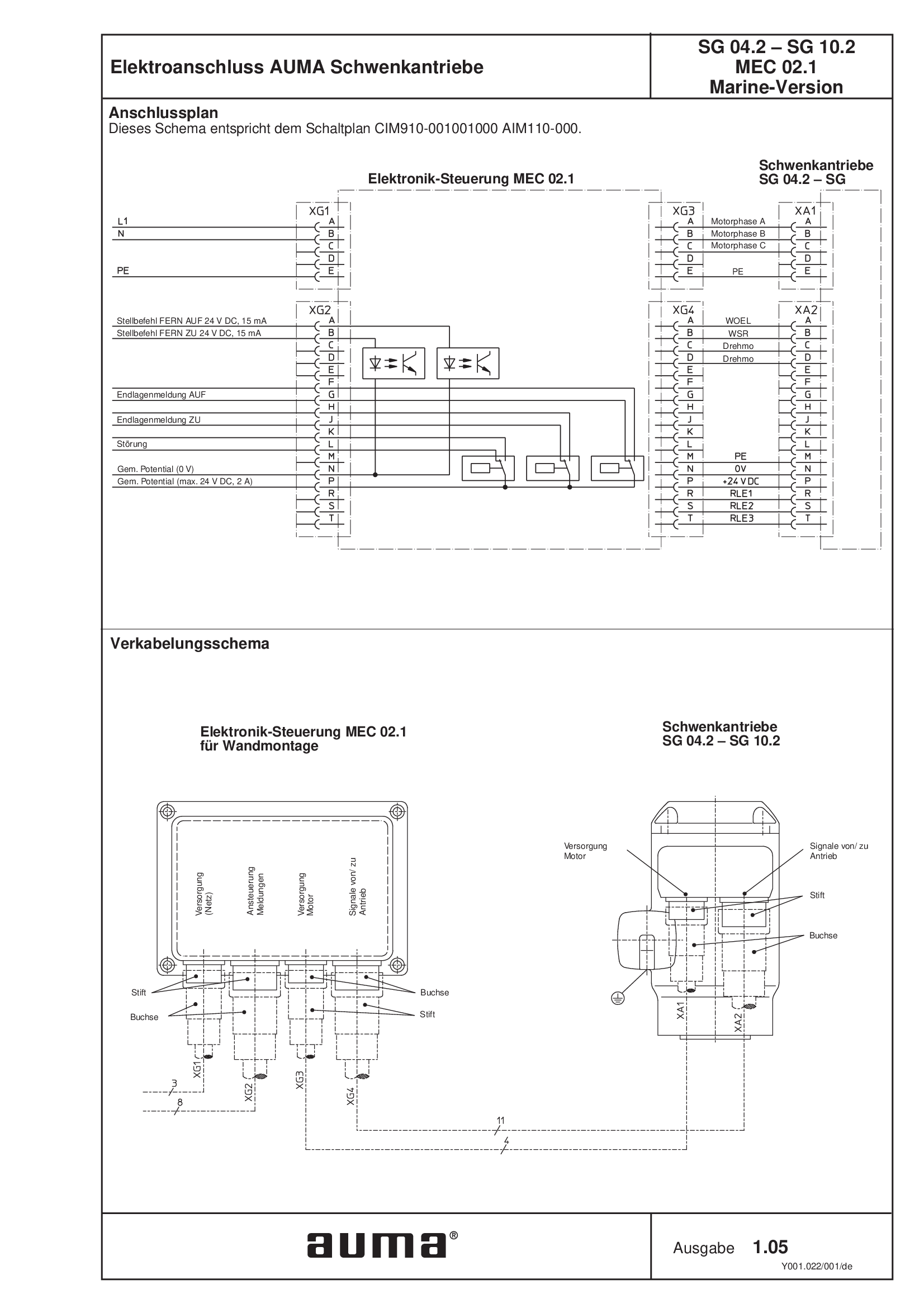
Part-turn actuators SG 04.2 - 10.2 MEC 02.1, military shipbuilding
Wiring diagram

Part-turn actuators SGC/SGCR, Valve actuators SVC/SVCR (basic version)
Wiring diagram

Part-turn actuators SGC/SGCR, Valve actuators SVC/SVCR, Profibus DP
Wiring diagram

Part-turn actuators SGCR, Valve actuators SVCR (with positioner)
Wiring diagram

Part-turn actuators SGM/SGMR, Valve actuators SVM/SVMR (basic version)
Wiring diagram

Part-turn actuators SGM/SGMR, Valve actuators SVM/SVMR, Profibus DP
Wiring diagram

Part-turn actuators SGMR, Valve actuators SVMR (with positioner)
Wiring diagram
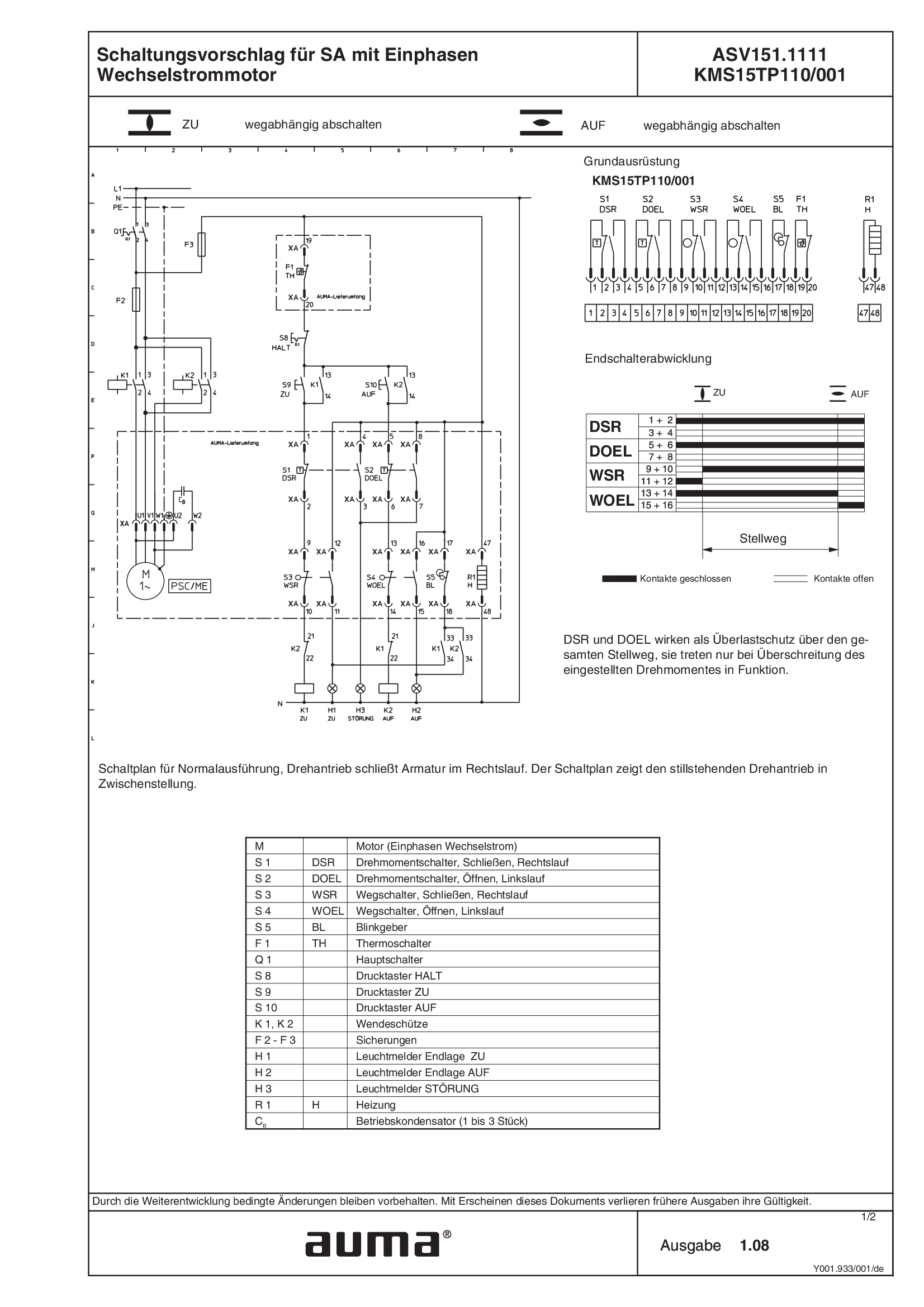
SA.1, 1-ph AC, ASV151.1111 /ASV151.1121 KMS15TP110/001
Wiring diagram
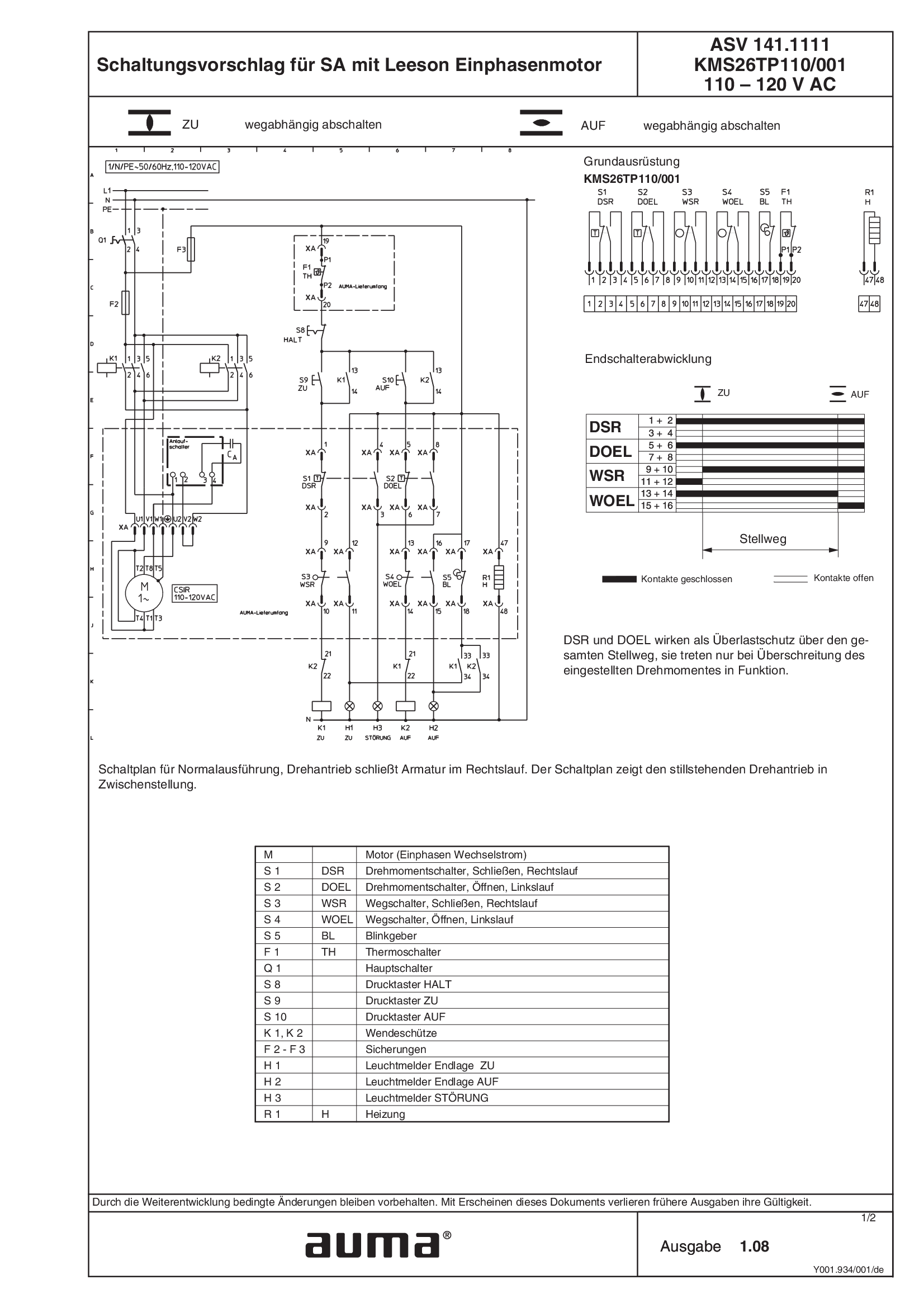
SA.1, 1-ph AC, Leeson motor ASV141.1111 /ASV141.1121 KMS26TP110/001 110 - 120 V AC
Wiring diagram
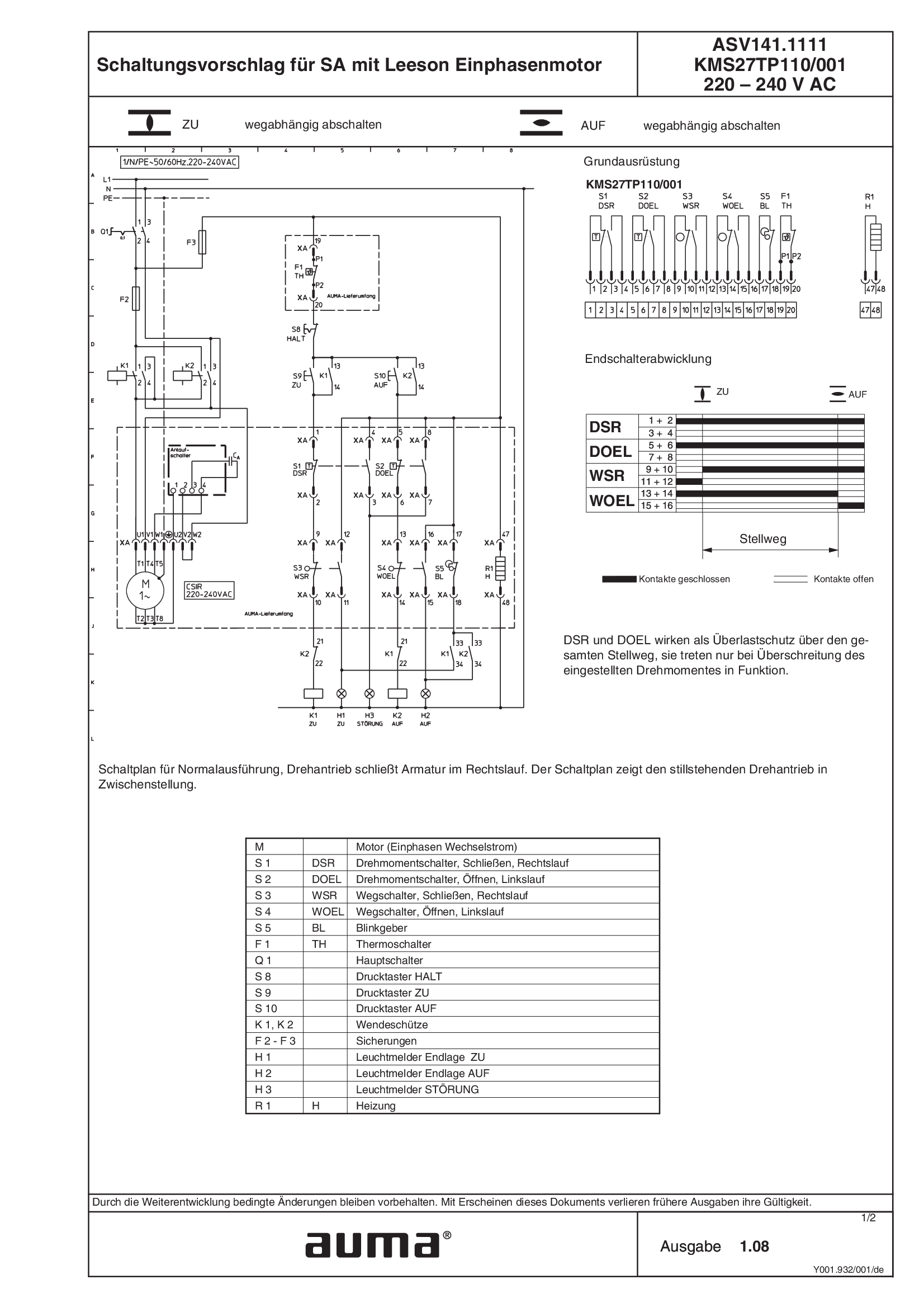
SA.1, 1-ph AC, Leeson motor ASV141.1111 /ASV141.1121 KMS27TP110/001 220 - 240 V AC
Wiring diagram
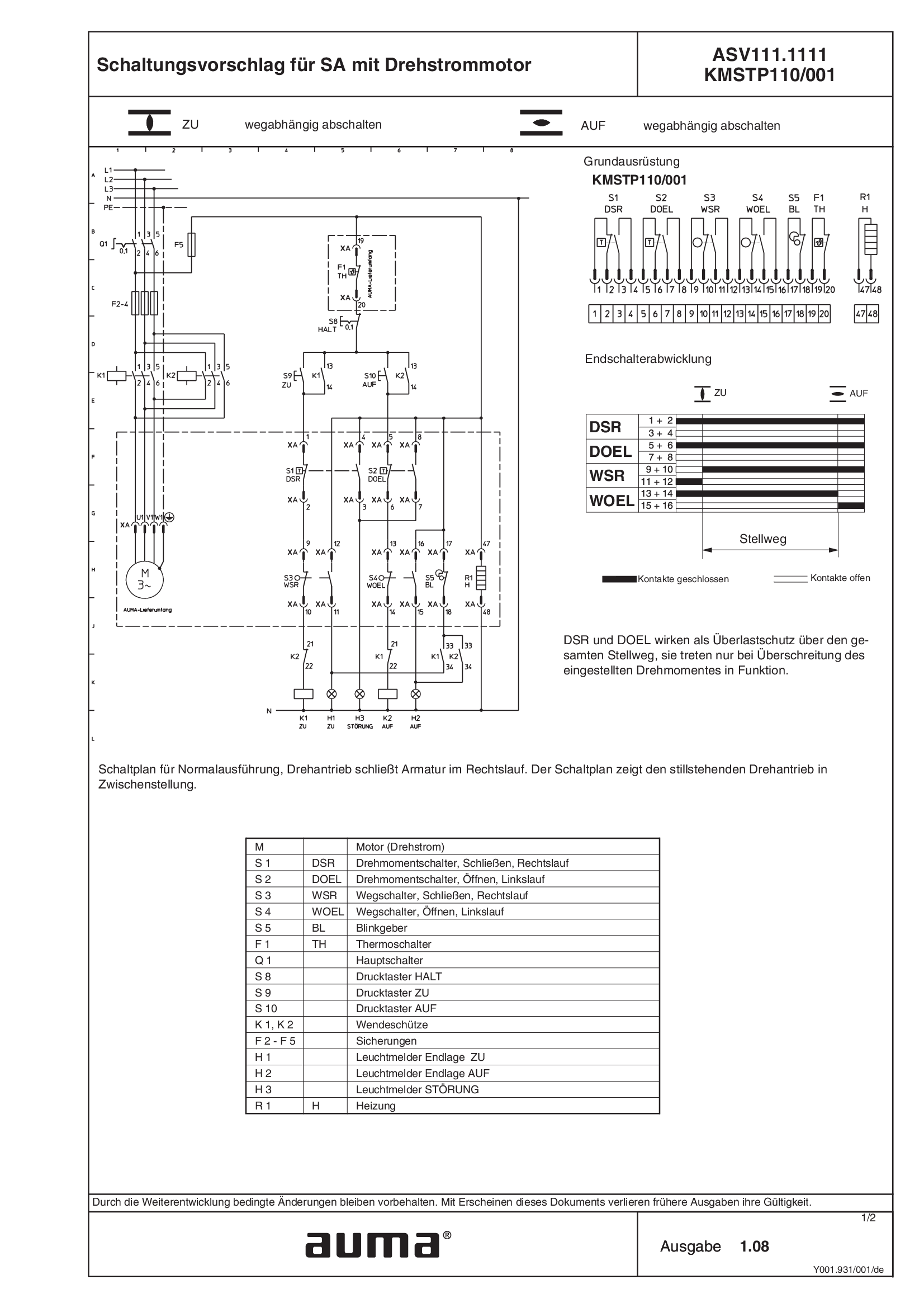
SA.1, 3-ph AC ASV111.1111 /ASV111.1121 KMSTP110/001
Wiring diagram
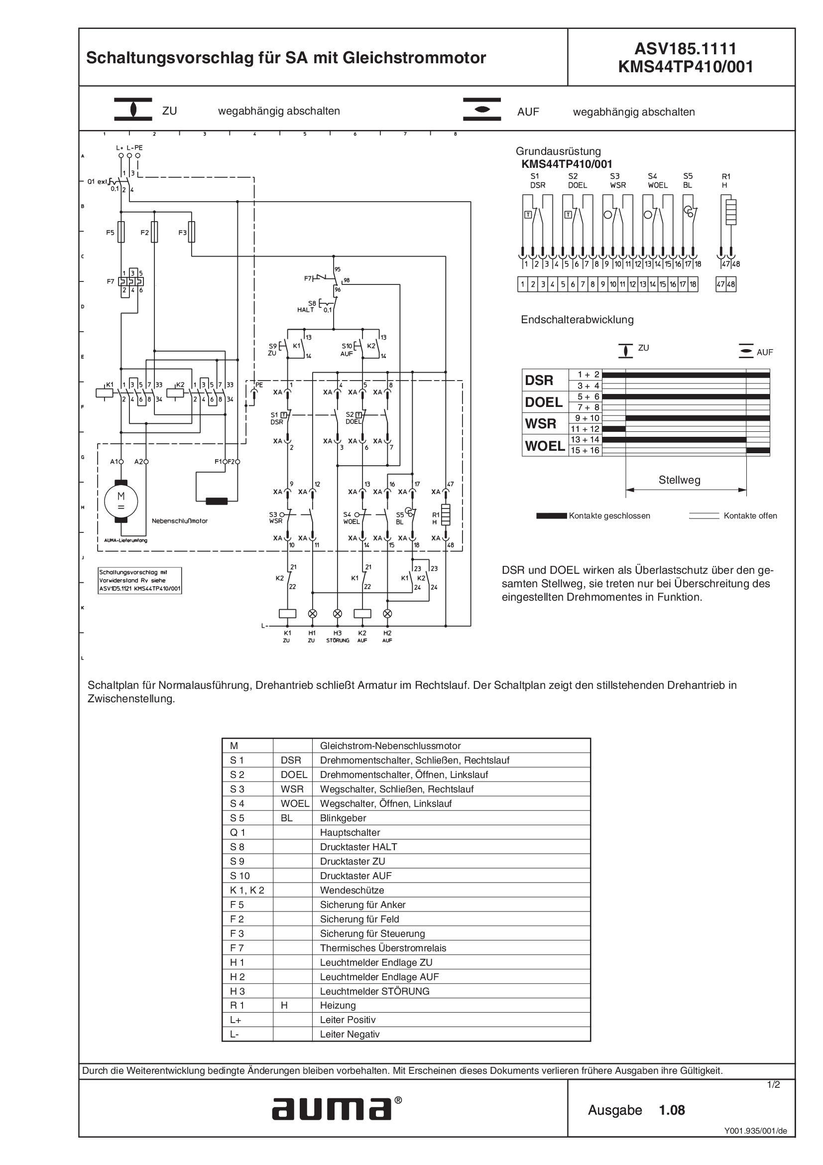
SA.1, DC ASV185.1111 /ASV185.1121 KMSTP410/001
Wiring diagram
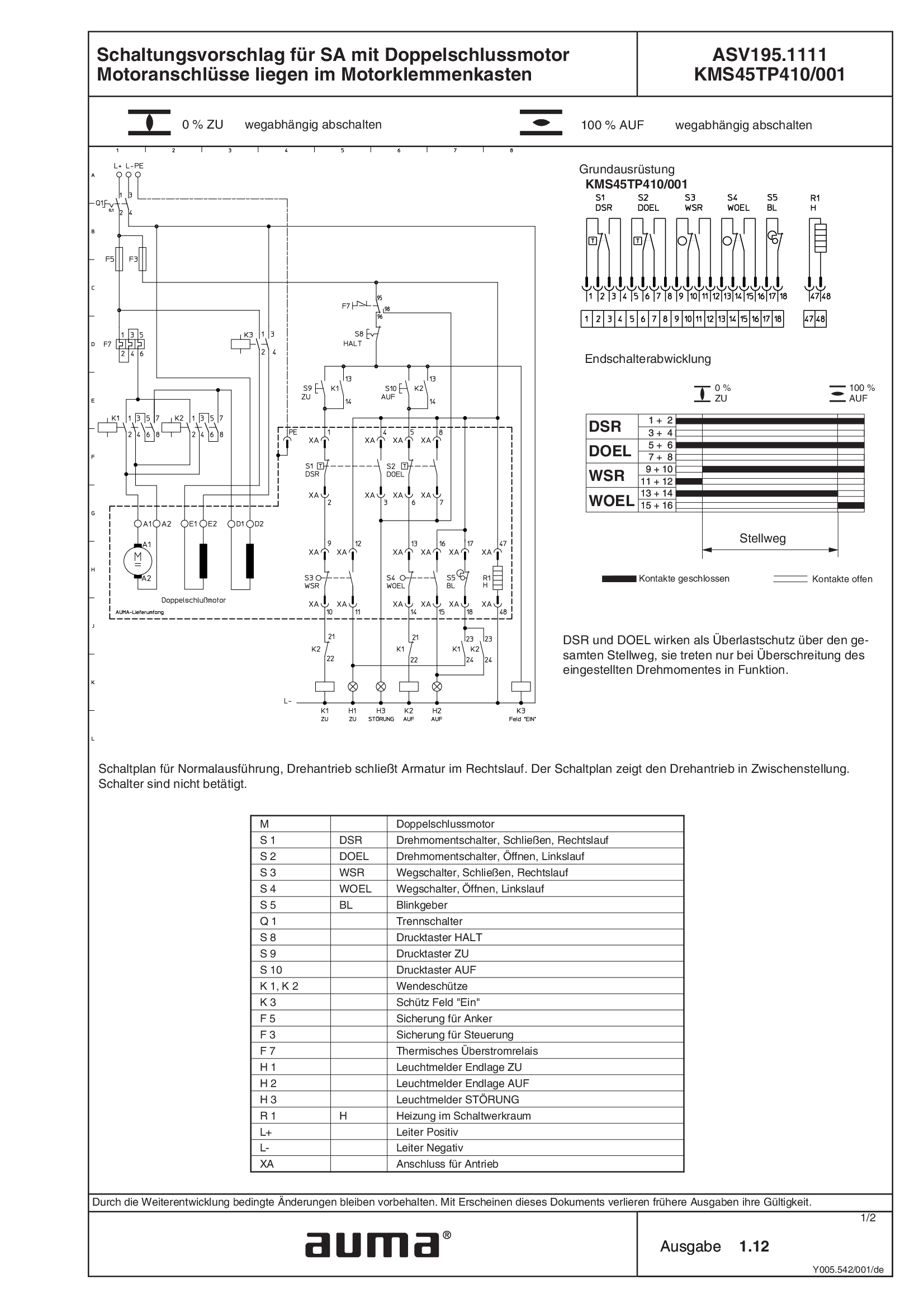
SA.1, DC ASV195.1111/ASV195.1121 KMS45TP410/001, compound motor, motor connections with motor terminal box
Wiring diagram

SA.1, DC ASV195.1111/ASV195.1121 KMS63TP410/001, compound motor, motor connection with plug/socket connector
Wiring diagram
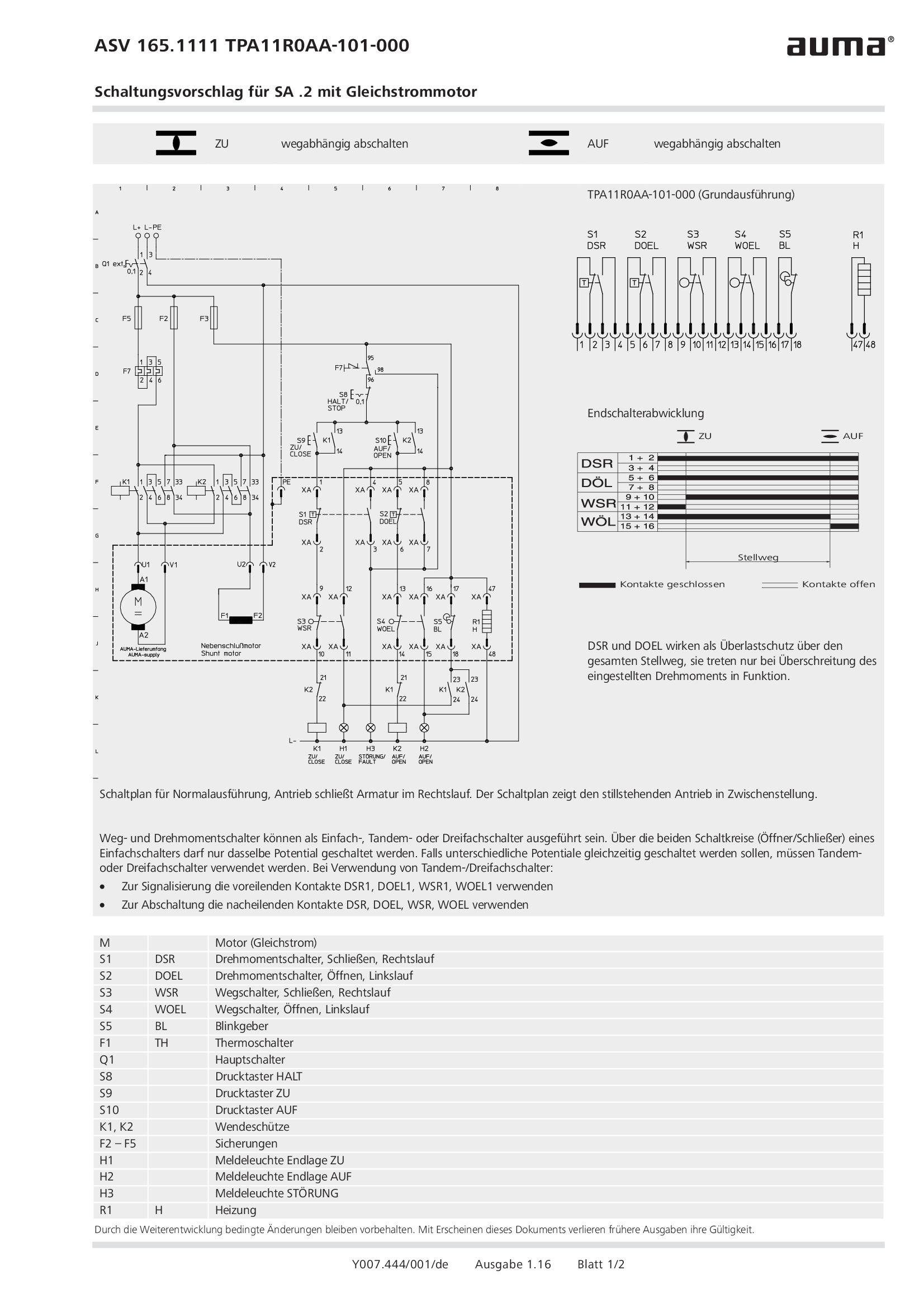
SA.2, DC ASV165.1111 /ASV165.1121 TPA11R0AA-101-000
Wiring diagram
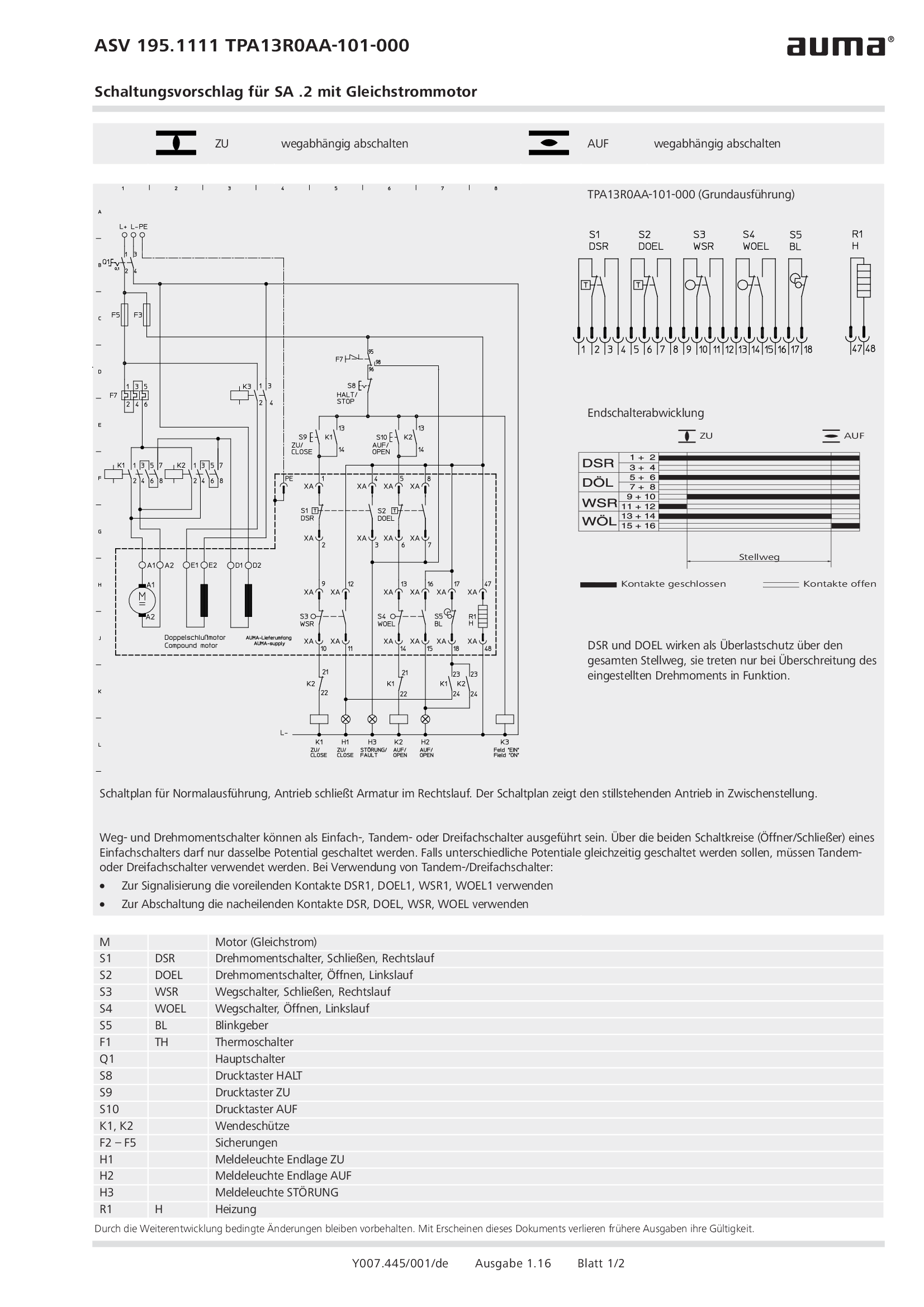
SA.2, DC ASV195.1111 /ASV195.1121 TPA13R0AA-101-000
Wiring diagram
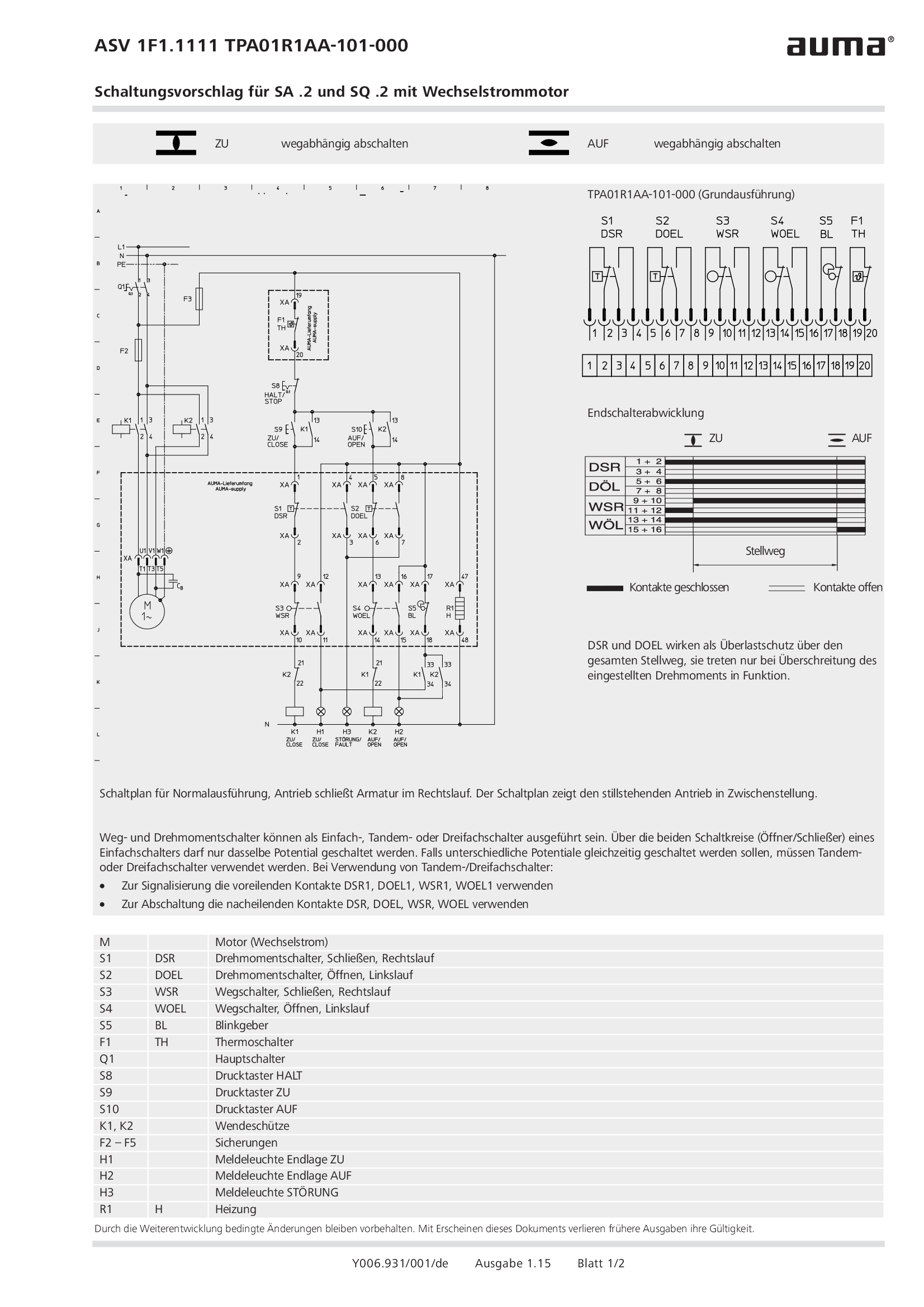
SA.2/SQ.2, 1-ph AC ASV1F1.1111 /ASV1F1.1121 TPA01R1AA-101-000
Wiring diagram
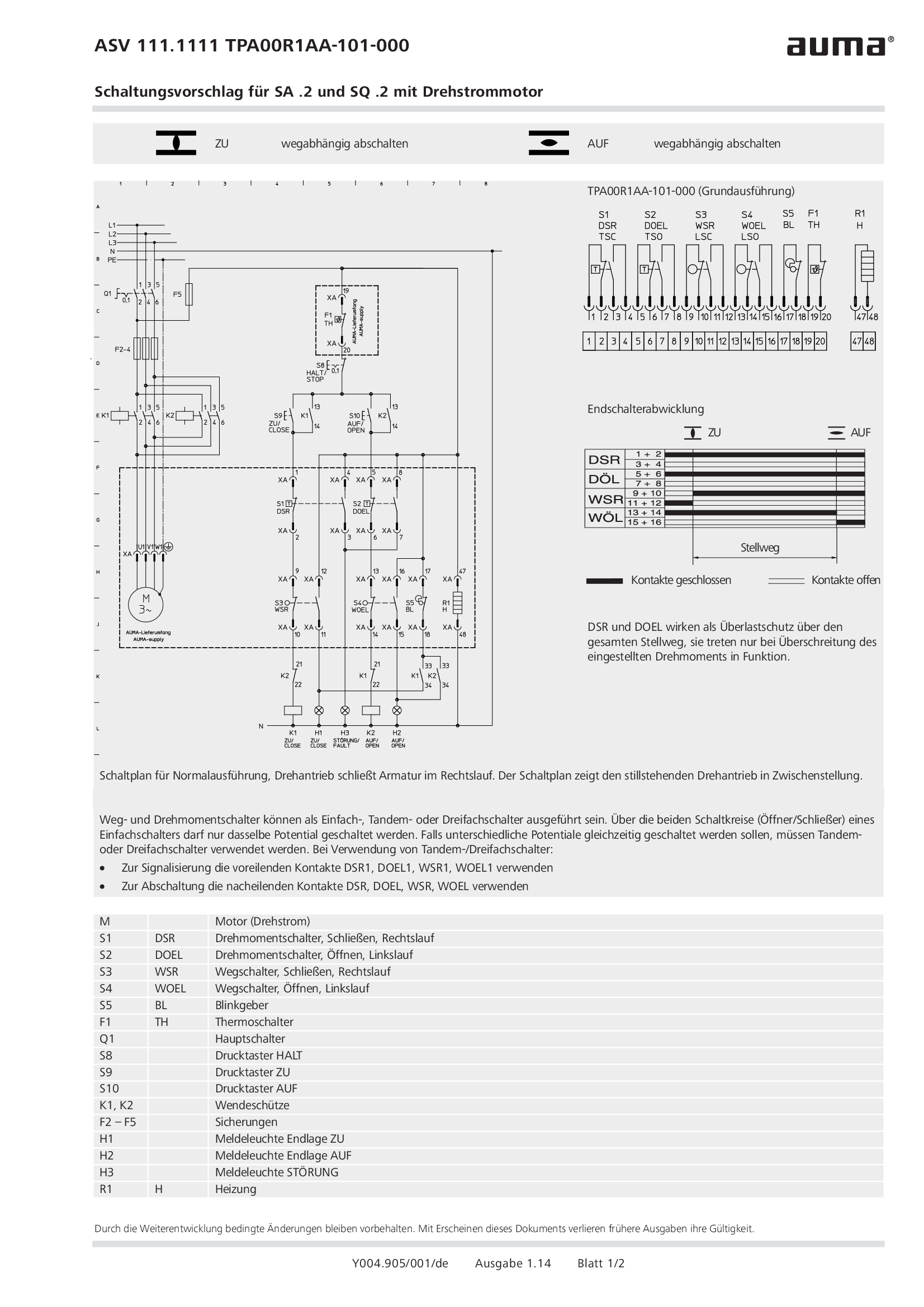
SA.2/SQ.2, 3-ph AC ASV111.1111 /ASV111.1121 TPA00R1AA-101-000
Wiring diagram
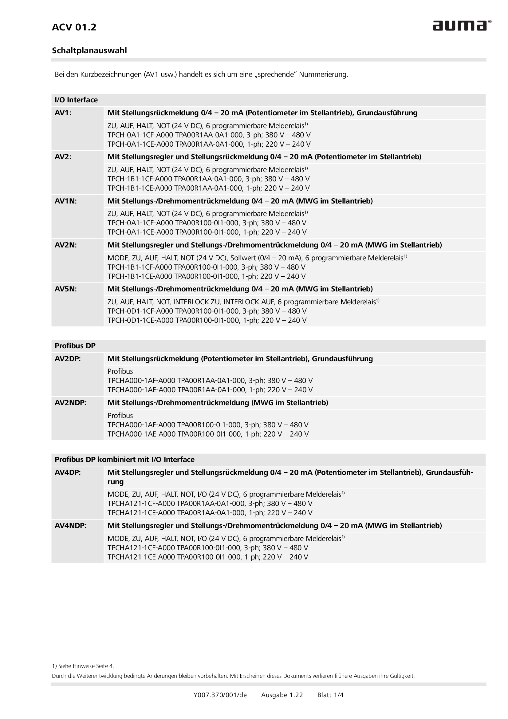
Selection for wiring diagram for ACV 01.2
Wiring diagram
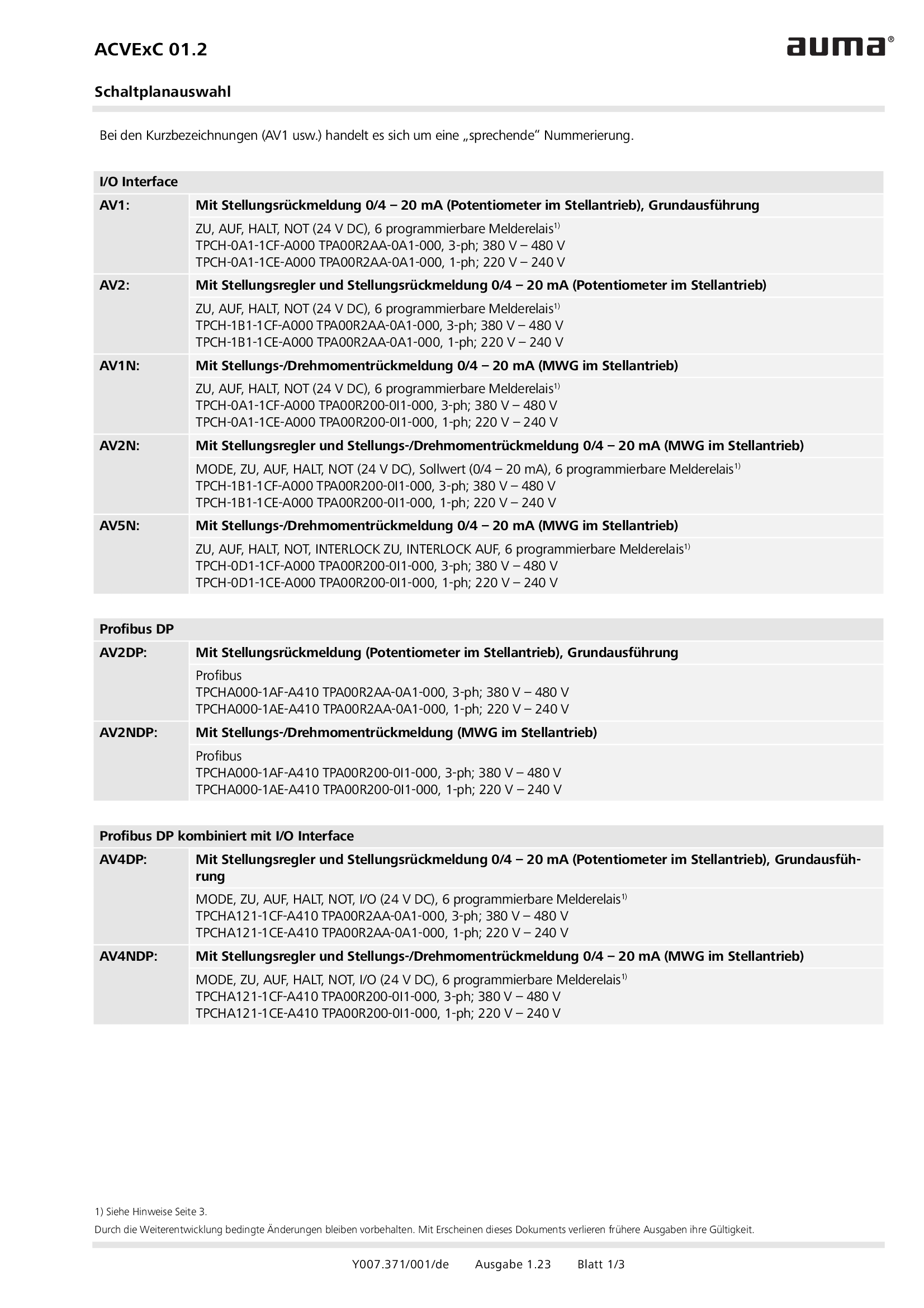
Selection for wiring diagram for ACVExC 01.2
Wiring diagram
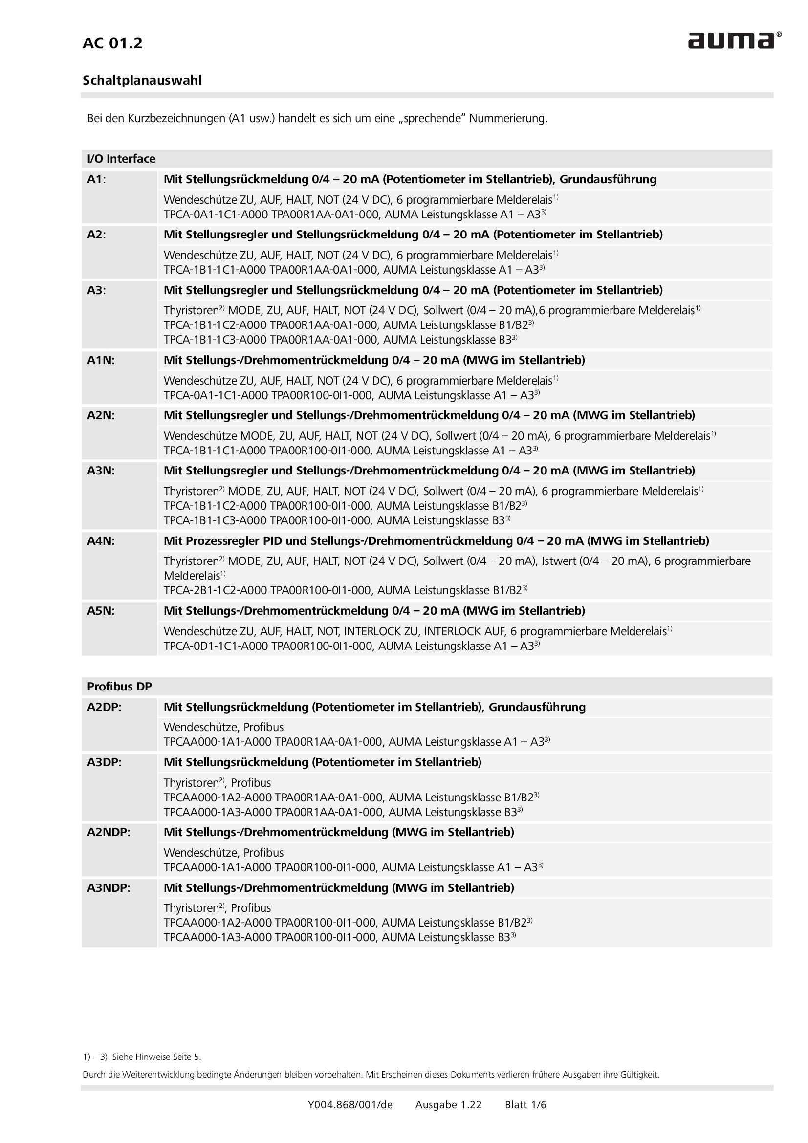
Selection for wiring diagram for AUMATIC AC 01.2
Wiring diagram
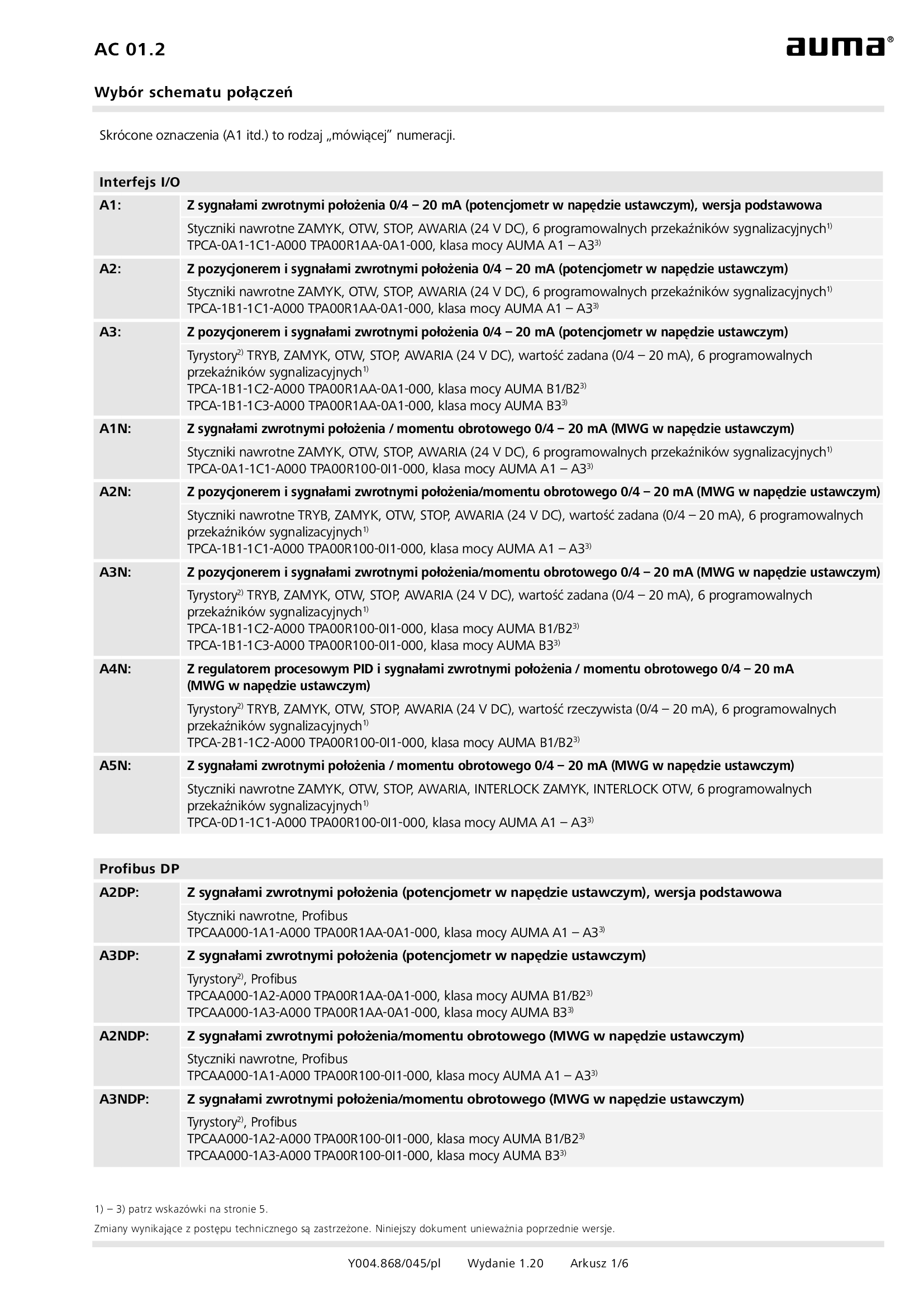
Selection for wiring diagram for AUMATIC AC 01.2/ACExC 01.2
Wiring diagram
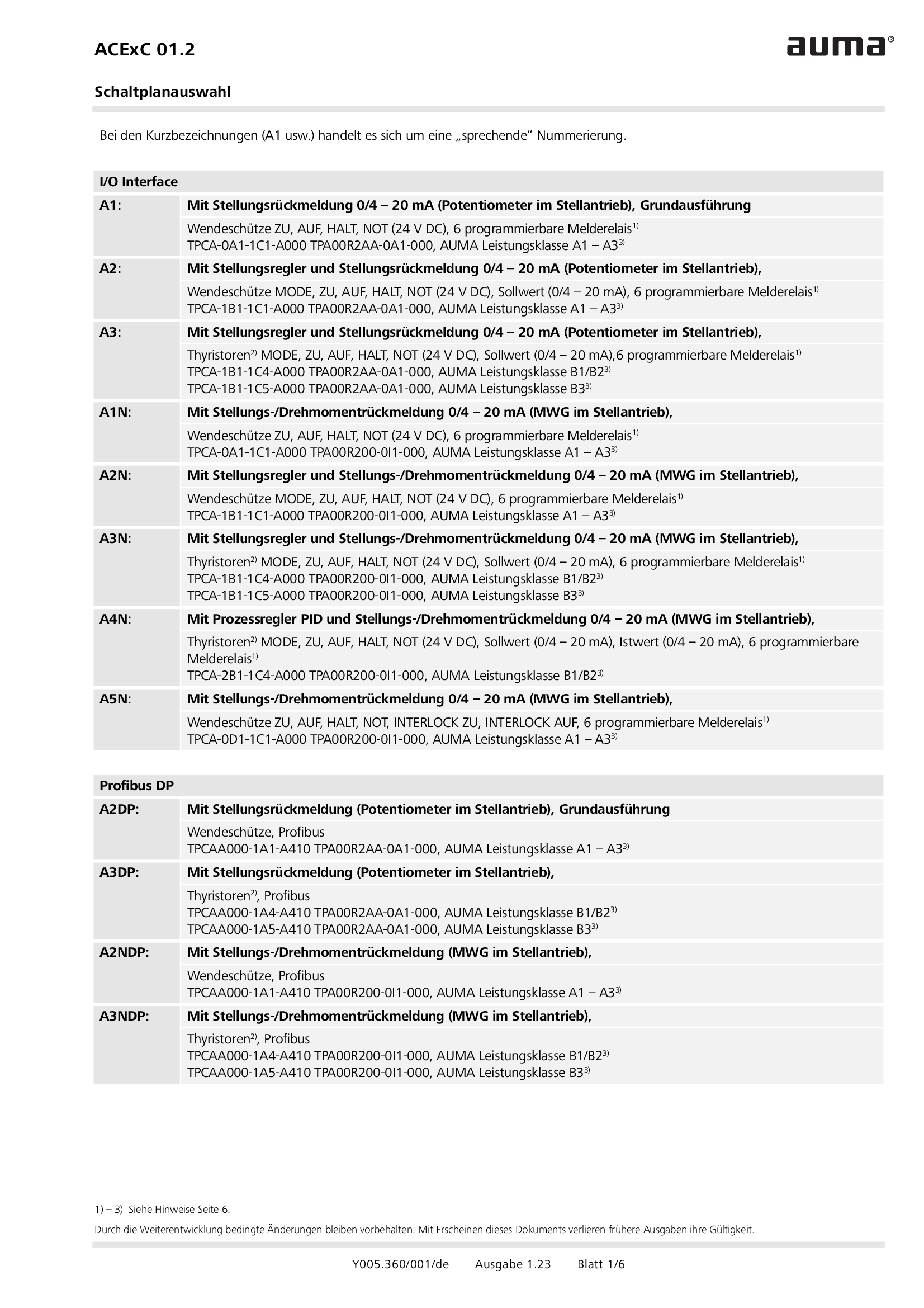
Selection for wiring diagram for AUMATIC ACExC 01.2
Wiring diagram
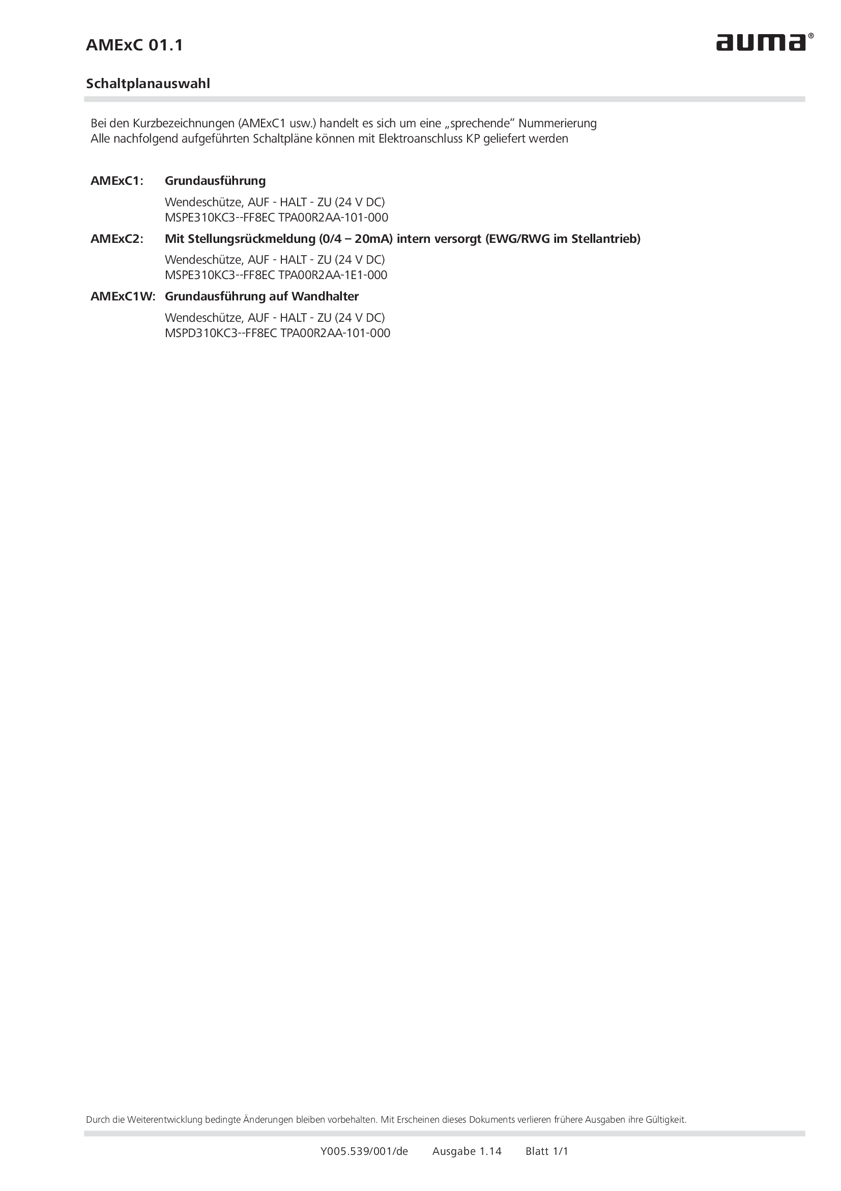
Selection of wiring diagrams for AUMA MATIC AMExC
Wiring diagram
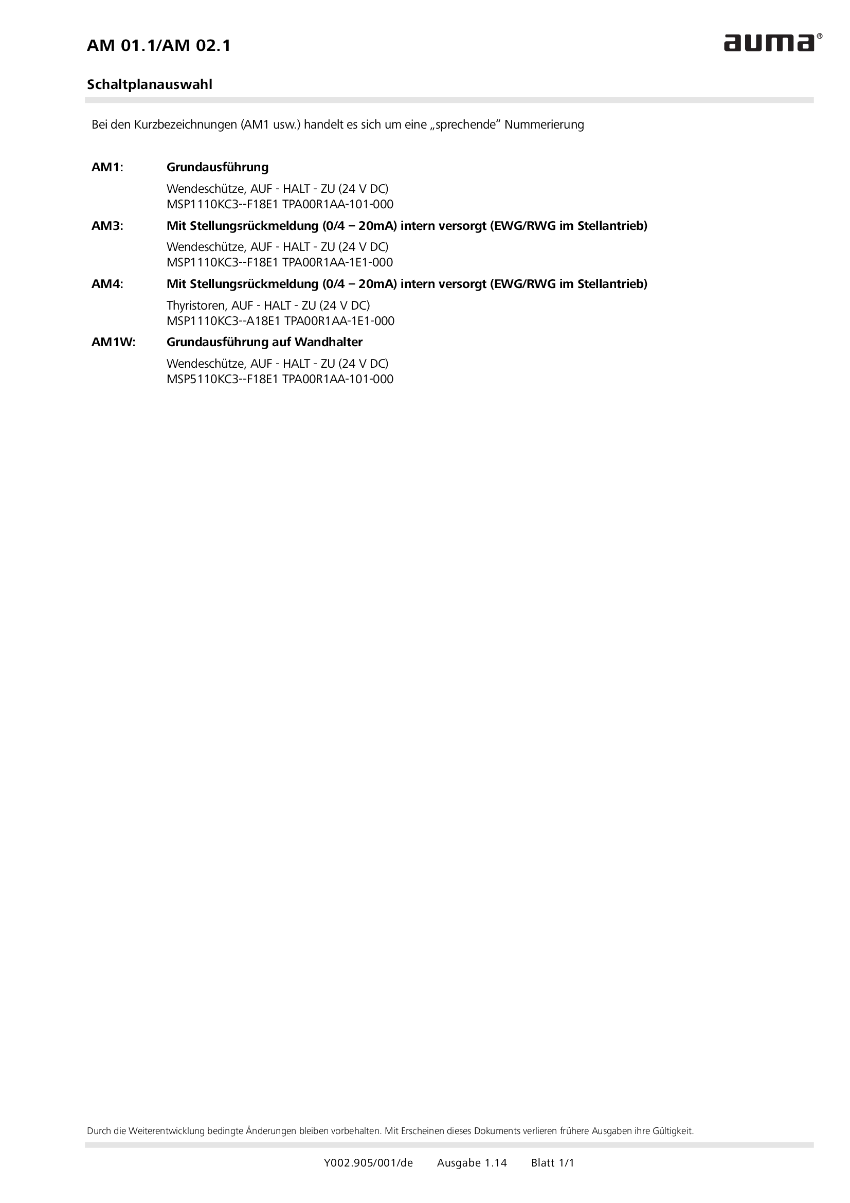
Selection of wiring diagrams for MATIC AM 01.1/AM 02. 1
Wiring diagram
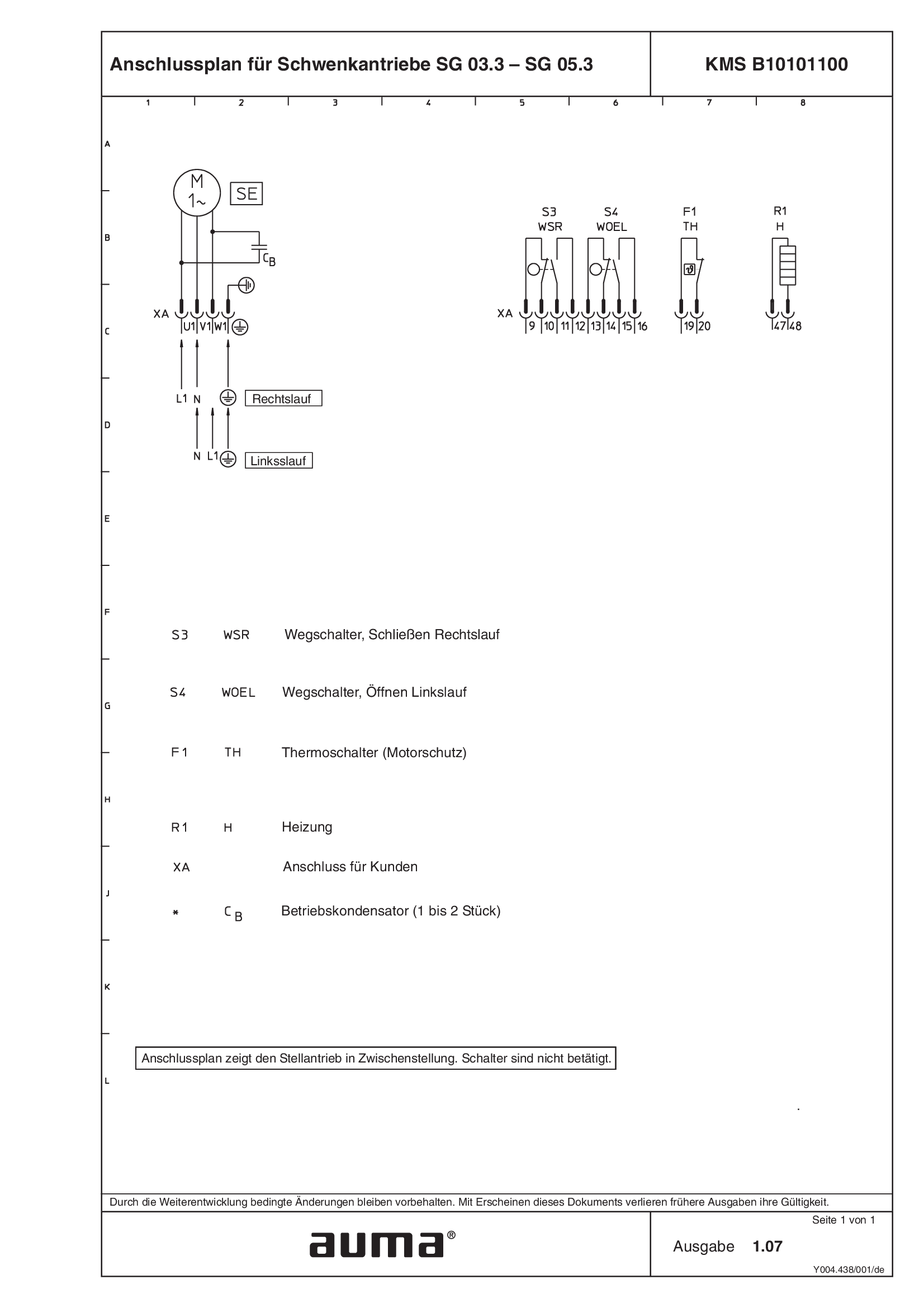
Terminal plan SG.3 - KMS B10101100
Wiring diagram

Terminal plans KMS, SA(R)N 07.1 - 25.1
Wiring diagram
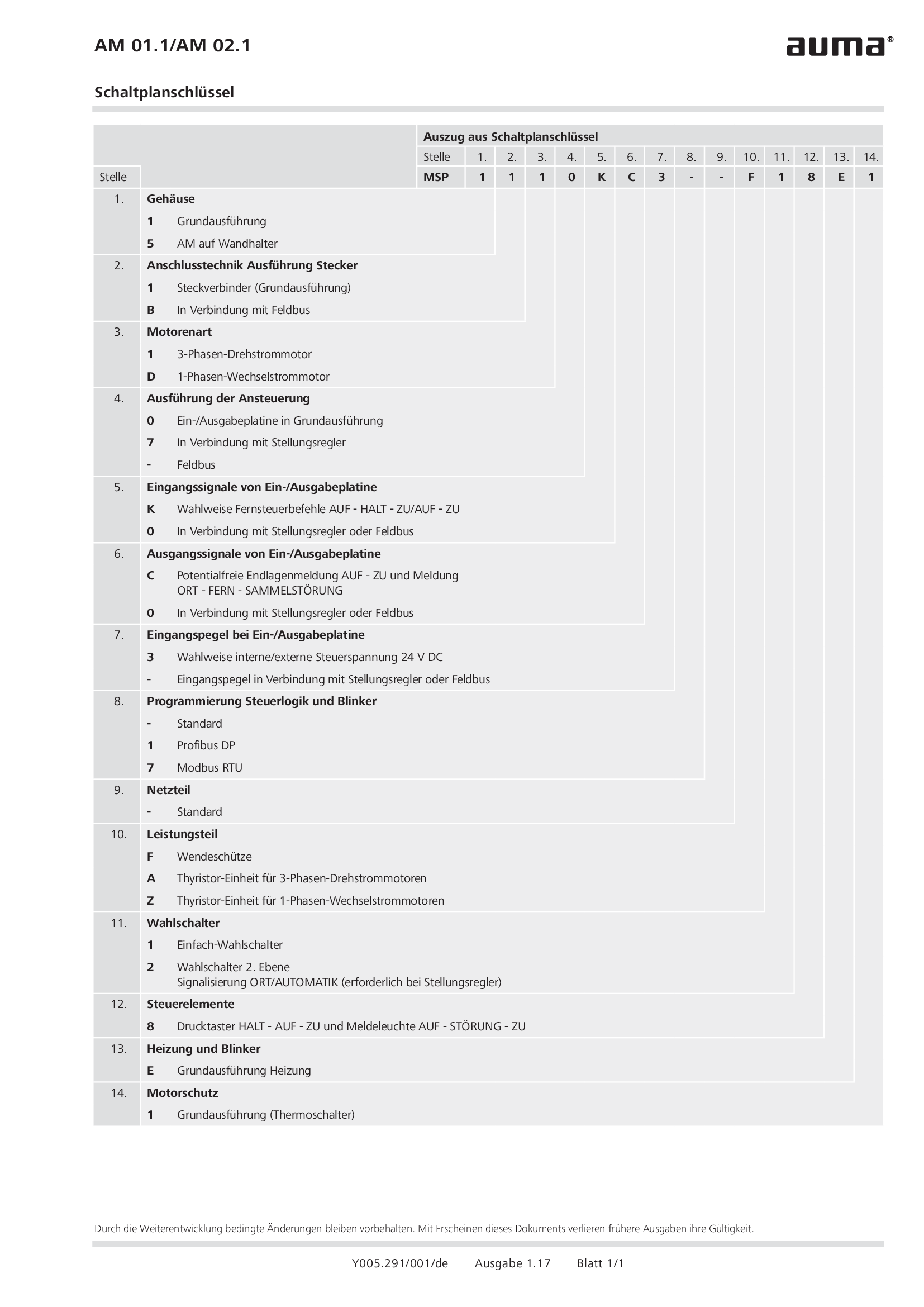
Wiring diagram code AM 01.1/AM 02.1
Wiring diagram
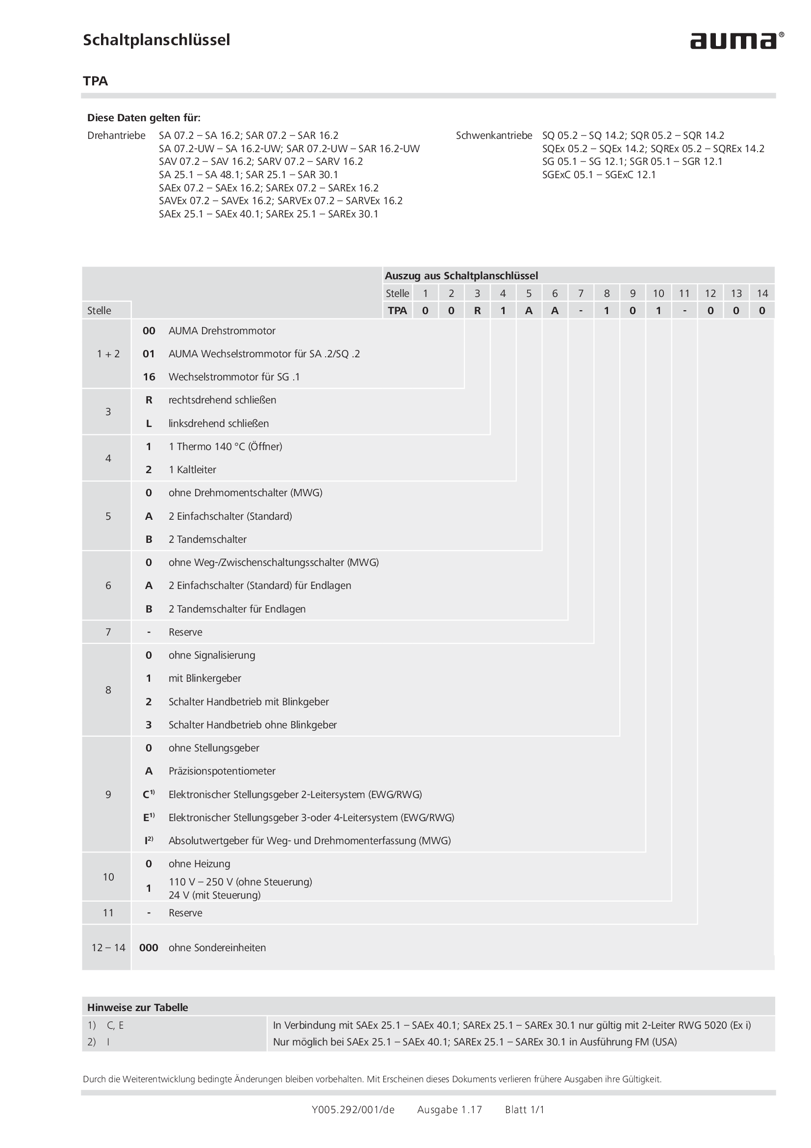
Wiring diagram code TPA
Wiring diagram
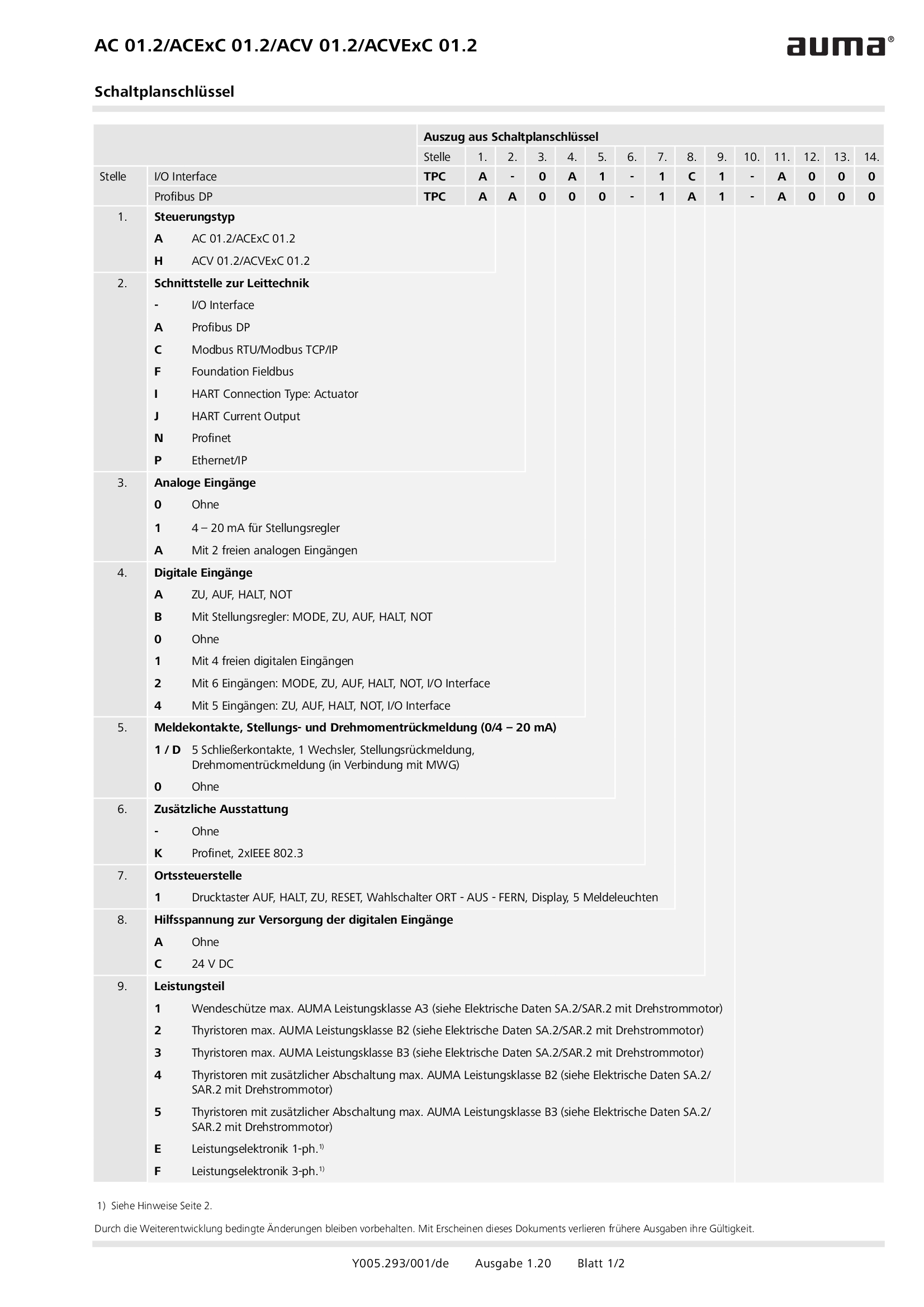
Wiring diagram code for AC 01.2/ACExC 01.2/ACV 01.2/ACVExC 01.2
Wiring diagram
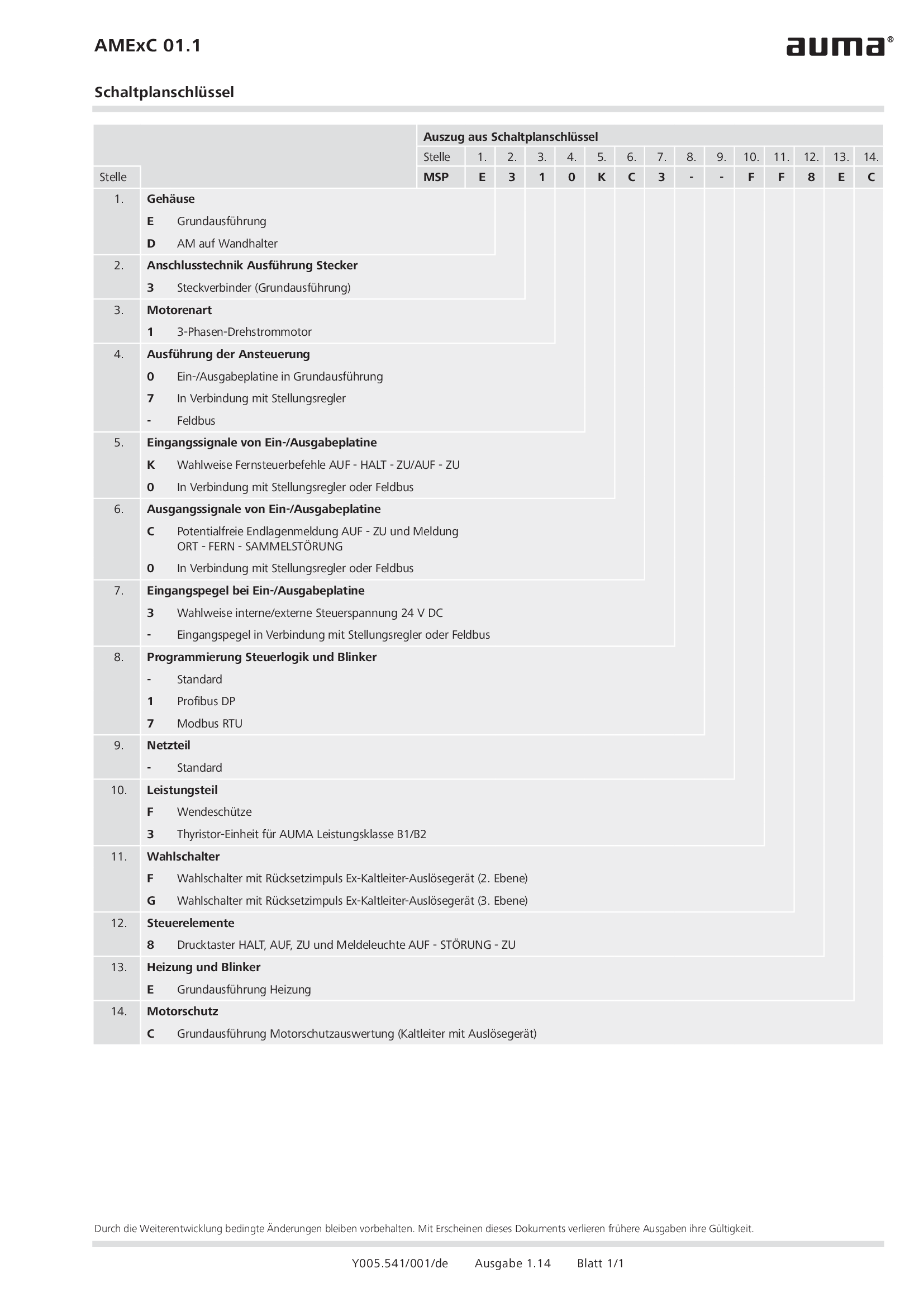
Wiring diagram code for AMExC 01.1
Wiring diagram


