Результаты поиска для
"Actuator controls AUMATIC ACVExC 01.2, Profibus DP"
Wiring diagram

A3NMB: AUMATIC ACExC 01.2 position/torque feedback (MWG in actuator), thyristors, Modbus, AUMA power class B3
Wiring diagram

A3NMBTCP: AUMATIC AC 01.2 position/torque feedback (MWG in actuator), Thyristors, Modbus TCP/IP, AUMA power class B1/B2
Wiring diagram

A3NMBTCP: AUMATIC AC 01.2 position/torque feedback (MWG in actuator), Thyristors, Modbus TCP/IP, AUMA power class B3
Wiring diagram

A3NMBTCP: AUMATIC ACExC 01.2 position/torque feedback (MWG in actuator), Thyristors, Modbus TCP/IP, AUMA power class B1/B2
Wiring diagram

A3NMBTCP: AUMATIC ACExC 01.2 position/torque feedback (MWG in actuator), Thyristors, Modbus TCP/IP, AUMA power class B3
Wiring diagram

A3NPN: AUMATIC AC 01.2, position/torque feedback (MWG in actuator), Thyristors, Profinet, AUMA power class B1/B2
Wiring diagram

A3NPN: AUMATIC AC 01.2, position/torque feedback (MWG in actuator), Thyristors, Profinet, AUMA power class B3
Wiring diagram

A3PN: AUMATIC AC 01.2 position feedback (potentiometer in actuator), Thyristors, Profinet, AUMA power class B1/B2
Wiring diagram

A3PN: AUMATIC AC 01.2 position feedback (potentiometer in actuator), Thyristors, Profinet, AUMA power class B3
Wiring diagram

A4DP: AUMATIC AC 01.2 positioner and position feedback signal 0/4 - 20 mA (potentiometer in actuator),basic version, reversing contactors MODE, CLOSE, OPEN, STOP, EMERGENCY, I/O (24 V DC), Profibus DP, AUMA power class A1 - A3
Wiring diagram

A4DP: AUMATIC ACExC 01.2 positioner and position feedbacck signal 0/4 - 20 mA (potentiometer in actuator), basic version, reversing contactors MODE, CLOSE, OPEN, STOP, EMERGENCY, I/O (24 V DC), 6 programmable output contacts, Profibus, power class A
Wiring diagram

A4ENIP: AUMATIC AC 01.2 positioner and position feedback signal 0/4 - 20 mA (potentiometer in actuator), basic version, reversing contactors MODE, CLOSE, OPEN, STOP, EMERGENCY, I/O (24 V DC), 6 programmable output contacts Ethernet/IP, AUMA power class
Wiring diagram

A4ENIP: AUMATIC ACExC 01.2 positioner and position feedback signal 0/4 - 20 mA (poti in actuator), basic version, reversing contactors MODE, CLOSE, OPEN, STOP, EMERGENCY, I/O (24 V DC), 6 programmable output contacts, EtherNet/IP, AUMA power class A1-A3
Wiring diagram

A4FF: AUMATIC AC 01.2 positioner and position feedback signal 0/4 – 20 mA (potentiometer in actuator), basic version, Reversing contactors MODE, CLOSE, OPEN, STOP, EMERGENCY, I/O (24V DC), 6 programmable output contacts, FF, AUMA power classes A1-A3
Wiring diagram

A4FF: AUMATIC ACExC 01.2 positioner and position feedback signal 0/4-20 mA (poti in actuator), basic version, reversing contactors MODE, CLOSE, OPEN, STOP, EMERGENCY, I/O (24 V DC),6 prorammable output contact, Foundation Fieldbus, AUMA power class A1-A3
Wiring diagram

A4HRT: AUMATIC AC 01.2 positioner and position feedback signal 0/4-20mA (potentiometer in actuator), basic version, Reversing contactors MODE, CLOSE, OPEN, STOP, EMERGENCY, I/O (24V DC), 6 programmable output contacts, HART, AUMA power classes A1 – A3
Wiring diagram

A4HRTCO: AUMATIC AC 01.2 positioner and position feedback signal 0/4-20mA (potentiometer in actuator), basic version, Reversing contactors MODE, CLOSE, OPEN, STOP, EMERGENCY, I/O (24V DC), 6 programmable output contacts, HART, AUMA power classes A1-A3
Wiring diagram

A4MB: AUMATIC AC 01.2 positioner and position feedback signal 0/4 - 20 mA (potentiometer in actuator), basic version, reversing contactors MODE, CLOSE, OPEN, STOP, EMERGENCY, I/O (24 V DC), 6programmable output contacts, Modbus RTU, power class A1 - A3
Wiring diagram

A4MB: AUMATIC ACExC 01.2 positioner and position feedback signal 0/4 - 20 mA (potentiometer in actuator), basic version, reversing contactors MODE, CLOSE, OPEN, STOP, EMERGENCY, I/O(24 V DC), 6 programmable output contacts, Modbus, AUMA power class
Wiring diagram

A4N: AUMATIC AC 01.2 process controller and position/torque feedback signal 0/4 - 20 mA (MWG in actuator), thyristors CLOSE, OPEN, STOP, EMERGENCY, MODE (24 V DC), 6 programmable output contacts, AUMA power class B1/B2
Wiring diagram

A4NDP: AUMATIC AC 01.2 positioner and position/torque feedback signal 0/4 - 20 mA (MWG in actuator), reversing contactors MODE, CLOSE, OPEN, STOP, EMERGENCY, I/O (24 V DC), 6 programmable output contacts, Profibus DP, AUMA power class A1 - A3
Wiring diagram

A4NDP: AUMATIC ACExC 01.2 positioner and position/torque feedback signal 0/4 - 20 mA (MWG in actuator), reversing contactors MODE, CLOSE, OPEN, STOP, EMERGENCY, I/O (24 V DC), 6 programmable output contacts, Profibus, AUMA power class A1 - A3
Wiring diagram

A4NENIP: AUMATIC AC 01.2 positioner and position/torque feedbacksignal 0/4 - 20 mA (MWG in actuator), reversing contactors MODE, CLOSE, OPEN, STOP, EMERGENCY, I/O (24 v DC), 6 programmable output contacts, EtherNet/IP, AUMA power class A1 - A3
Wiring diagram

A4NENIP: AUMATIC ACExC 01.2 positioner and position/torque feedback signal 0/4 - 20 mA (MWG in actuator), reversing contactors MODE, CLOSE, OPEN, STOP, EMERGENCY, I/O (24 V DC), 6 programmable output contacts, EtherNet/IP, AUMA power class A1 - A3
Wiring diagram

A4NFF: AUMATIC ACExC 01.2 positioner and position/torque feedback signal 0/4 - 20 mA (MWG in actuator), reversing contactors MODE, CLOSE, OPEN, STOP, EMERGENCY, I/O (24 V DC), 6 programmable output contacts, Foundation Fieldbus, AUMA power class A1 - A3
Wiring diagram

A4NHRT: AUMATIC AC 01.2 positioner and position/torque feedback signal 0/4 – 20 mA (MWG in actuator), Reversing contactors MODE, CLOSE, OPEN, STOP, EMERGENCY, I/O (24 V DC), 6 programmable output contacts, HART, AUMA power classes A1 – A3
Wiring diagram

A4NHRT: AUMATIC ACExC 01.2 positioner and position/torque feedback signal 0/4 - 20 mA MWG in actuator), reversing contactors MODE, CLOSE, OPEN, STOP, EMERGENCY, I/O (24 V DC), 6 programmable output contacts, HART actuator, AUMA power class A1 - A3
Wiring diagram

A4NHRTCO: AUMATIC AC 01.2 position/torque feedback (MWG in actuator), Reversing contactors MODE, CLOSE, OPEN, STOP, EMERGENCY, I/O (24 V DC), 6 programmable output contacts, HART current output, AUMA power classes A1 – A3
Wiring diagram

A4NHRTCO: AUMATIC ACExC 01.2 position/torque feedback (MWG in actuator), reversing contactors MODE, CLOSE, OPEN, STOP, EMERGENCY, I/O (24 V DC), 6 programmable output contacts, HART current output, AUMA power class A1 - A3
Wiring diagram

A4NMB: AUMATIC AC 01.2 positioner and position/torque feedback signal 0/4 - 20 mA (MWG in actuator), reversing contactors MODE, CLOSE, OPEN, STOP, EMERGENCY, I/O (24 V DC), 6 programmable output contacts, Modbus RTU, AUMA power class A1 - A3
Wiring diagram

A4NMB: AUMATIC ACExC 01.2 positioner and position/torque feedback signal 0/4 - 20 mA (MWG in actuator), reversing contactors MODE, CLOSE, OPEN, STOP, EMERGENCY, I/O (24 V DC), 6 programmable output contacts, Modbus, AUMA power class A1 - A3
Wiring diagram

A4NMBTCP: AUMATIC AC 01.2 positioner and position/torque feedback signal 0/4 – 20 mA (MWG in actuator), Reversing contactors MODE, CLOSE, OPEN, STOP, EMERGENCY, I/O (24 V DC), 6 programmable output contacts, Modbus RTU, AUMA power classes A1 – A3
Wiring diagram

A4NMBTCP: AUMATIC ACExC 01.2 positioner and position/torque feedback signal 0/4 - 20 mA (MWG in actuator), reversing contactors MODE, CLOSE, OPEN, STOP, EMERGENCY, I/O (24 V DC), 6 programmable output contacts, Modbus TPC/IP, AUMA power class A1 - A3
Wiring diagram

A5DP: AUMATIC AC 01.2 positioner and position feedback signal 0/4 - 20 mA (potentiometer in actuator), thyristors MODE, CLOSE, OPEN, STOP, EMERGENCY, I/O (24 V DC), 6 programmable output contacts, Profibus DP, AUMA power class B1/B2
Wiring diagram

A5DP: AUMATIC AC 01.2 positioner and position feedback signal 0/4 - 20 mA (potentiometer in actuator), thyristors MODE, CLOSE, OPEN, STOP, EMERGENCY, I/O (24 V DC), 6 programmable output contacts, Profibus DP, AUMA power class B3
Wiring diagram

A5DP: AUMATIC ACExC 01.2 positioner and position feedback signal 0/4 - 20 mA (potentiometer in actuator), thyristors MODE, CLOSE, STOP, EMERGENCY, I/O (24 V DC), 6 programmable ouput contacts, Profibus, AUMA power class B1/B2
Wiring diagram

A5DP: AUMATIC ACExC 01.2 positioner and position feedback signal 0/4 - 20 mA (potentiometer in actuator), thyristors MODE, CLOSE, STOP, EMERGENCY, I/O (24 V DC), 6 programmable ouput contacts, Profibus, AUMA power class B3
Wiring diagram

A5ENIP: AUMATIC AC 01.2 positioner and position feedback signal 0/4 - 20 mA (potentiometer in actuator), Thyristors, MODE, CLOSE, OPEN, STOP, EMERGENCY, I/O (24 V DC), 6 programmable output contacts, EtherNet/IP, AUMA power class B1 / B2
Wiring diagram

A5ENIP: AUMATIC AC 01.2 positioner and position feedback signal 0/4 - 20 mA (potentiometer in actuator), Thyristors, MODE, CLOSE, OPEN, STOP, EMERGENCY, I/O (24 V DC), 6 programmable output contacts, EtherNet/IP, AUMA power class B3
Wiring diagram

A5ENIP: AUMATIC ACExC 01.2 positioner and position feedback signal 0/4 - 20 mA (potentiometer in actuator), Thyristors MODE, CLOSE, OPEN, STOP, EMERGENCY, I/O (24 V DC), 6 programmable output contacts, EtherNet/IP, AUMA power class B1/B2
Wiring diagram

A5ENIP: AUMATIC ACExC 01.2 positioner and position feedback signal 0/4 - 20 mA (potentiometer in actuator), Thyristors MODE, CLOSE, OPEN, STOP, EMERGENCY, I/O (24 V DC), 6 programmable output contacts, EtherNet/IP, AUMA power class B3
Wiring diagram

A5FF: AUMATIC AC 01.2 positioner and position feedback signal 0/4 – 20 mA (potentiometer in actuator), Thyristors MODE, CLOSE, OPEN, STOP, EMERGENCY, I/O (24 V DC), 6 programmable output contacts, Foundation Fieldbus, AUMA power class B1/B2
Wiring diagram

A5FF: AUMATIC AC 01.2 positioner and position feedback signal 0/4 – 20 mA (potentiometer in actuator), Thyristors MODE, CLOSE, OPEN, STOP, EMERGENCY, I/O (24 V DC), 6 programmable output contacts, Foundation Fieldbus, AUMA power class B3
Wiring diagram

A5FF: AUMATIC AC 01.2 positioner and position feedback signal 0/4 – 20 mA (potentiometer in actuator), Thyristors MODE, CLOSE, OPEN, STOP, EMERGENCY, I/O (24 V DC), 6 programmable output contacts,´Foundation Fieldbus, AUMA power class B1/B2
Wiring diagram

A5FF: AUMATIC ACExC 01.2 positioner and position feedback signal 0/4-20 mA (potentiometer in actuator), Thyristors MODE, CLOSE, OPEN, STOP, EMERGENCY, I/O (24 V DC), 6 programmable output contacts, Foundation Fieldbus FF, AUMA power class B1/B2
Wiring diagram

A5FF: AUMATIC ACExC 01.2 positioner and position feedback signal 0/4-20 mA (potentiometer in actuator), Thyristors MODE, CLOSE, OPEN, STOP, EMERGENCY, I/O (24 V DC), 6 programmable output contacts, Foundation Fieldbus FF, AUMA power class B3
Wiring diagram

A5HRT: AUMATIC AC 01.2 positioner and position feedback signal 0/4 – 20 mA (potentiometer in actuator), Thyristors MODE, CLOSE, OPEN, STOP, EMERGENCY, I/O (24 V DC), 6 programmable output contacts, HART, AUMA power class B1/B2
Wiring diagram

A5HRT: AUMATIC AC 01.2 positioner and position feedback signal 0/4 – 20 mA (potentiometer in actuator), Thyristors MODE, CLOSE, OPEN, STOP, EMERGENCY, I/O (24 V DC), 6 programmable output contacts, HART, AUMA power class B3
Wiring diagram

A5HRT: AUMATIC ACExC 01.2 positioner and position feedback signal 0/4 - 20 mA (potentiometer in actuator), Thyristors MODE, CCLOSE, OPEN, STOP, EMERGENCY, I/O ( 24 V DC), 6 programmable output contracts, HART actuator AUMA power class B1/B2
Wiring diagram

A5HRT: AUMATIC ACExC 01.2 positioner and position feedback signal 0/4 - 20 mA (potentiometer in actuator), Thyristors MODE, CCLOSE, OPEN, STOP, EMERGENCY, I/O ( 24 V DC), 6 programmable output contracts, HART actuator AUMA power class B3
Wiring diagram

A5HRTCO: AUMATIC AC 01.2 position feedback (potentiometer in actuator), Thyristors MODE, CLOSE, OPEN, STOP, EMERGENCY, I/O (24 V DC), 6 programmable output contacts, HART Current Output, AUMA power class B1/B2
Wiring diagram

A5HRTCO: AUMATIC AC 01.2 position feedback (potentiometer in actuator), Thyristors MODE, CLOSE, OPEN, STOP, EMERGENCY, I/O (24 V DC), 6 programmable output contacts, HART Current Output, AUMA power class B3
Wiring diagram

A5HRTCO: AUMATIC ACExC 01.2 position feedback (potentiometer in actuator), Thyristors MODE, CLOSE, OPEN, STOP, EMERGENCY, IO (24 V DC), 6 programmable output contacts, HART current output, AUMA power class B1/B2
Wiring diagram

A5HRTCO: AUMATIC ACExC 01.2 position feedback (potentiometer in actuator), Thyristors MODE, CLOSE, OPEN, STOP, EMERGENCY, IO (24 V DC), 6 programmable output contacts, HART current output, AUMA power class B3
Wiring diagram

A5MB: AUMATIC AC 01.2 positioner and position feedback signal 0/4 - 20 mA (potentiometer in actuator), thyristors MODE, CLOSE, OPEN, STOP, EMERGENCY, I/O (24 V DC), 6 prgrammable output contacts, Modbus RTU, AUMA power class B1/B2
Wiring diagram

A5MB: AUMATIC AC 01.2 positioner and position feedback signal 0/4 - 20 mA (potentiometer in actuator), thyristors MODE, CLOSE, OPEN, STOP, EMERGENCY, I/O (24 V DC), 6 prgrammable output contacts, Modbus RTU, AUMA power class B3
Wiring diagram

A5MB: AUMATIC ACExC 01.2 positioner and position feedback signal 0/4 - 20 mA (potentiometer in actuator), thyristors MODE, CLOSE, OPEN, STOP, EMERGENCY, I/O (24 V DC), 6 programmable output contacts, Modbus, AUMA power class B1/B2
Wiring diagram

A5MB: AUMATIC ACExC 01.2 positioner and position feedback signal 0/4 - 20 mA (potentiometer in actuator), thyristors MODE, CLOSE, OPEN, STOP, EMERGENCY, I/O (24 V DC), 6 programmable output contacts, Modbus, AUMA power class B3
Wiring diagram

A5MBTCP: AUMATIC AC 01.2 positioner and position feedback signal 0/4 – 20 mA (potentiometer in actuator), Thyristors MODE, CLOSE, OPEN, STOP, EMERGENCY, I/O (24 V DC), 6 programmable output contacts, Modbus TCP/IP, AUMA power class B1/B2
Wiring diagram

A5MBTCP: AUMATIC AC 01.2 positioner and position feedback signal 0/4 – 20 mA (potentiometer in actuator), Thyristors MODE, CLOSE, OPEN, STOP, EMERGENCY, I/O (24 V DC), 6 programmable output contacts, Modbus TCP/IP, AUMA power class B3
Wiring diagram

A5MBTCP: AUMATIC ACExC 01.2 positioner and position feedback signal 0/4 - 20 mA (potentiometer in actuator), Thyristors MODE, CLOSE, OPEN, STOP, EMERGENCY, I/O (24V DC), 6 programmable output contacts, Modbus TPC/IP, AUMA power class B1/B2
Wiring diagram

A5MBTCP: AUMATIC ACExC 01.2 positioner and position feedback signal 0/4 - 20 mA (potentiometer in actuator), Thyristors MODE, CLOSE, OPEN, STOP, EMERGENCY, I/O (24V DC), 6 programmable output contacts, Modbus TPC/IP, AUMA power class B3
Wiring diagram

A5N: AUMATIC AC 01.2 position/torque feedback signal 0/4 - 20 mA (MWG in actuator), reversing contactors CLOSE, OPEN, STOP, EMERGENCY, INTERLOCK CLOSE, INTERLOCK OPEN, 6 programmable output contacts, AUMA power class A1 - A3
Wiring diagram

A5N: AUMATIC ACExC 01.2 position/torque feedback signal 0/4 - 20 mA (MWG in actuator), reversing contactors CLOSE, OPEN, STOP, EMERGENCY, INTERLOCK CLOSE, INTERLOCK OPEN, 6 programmable output contacts, AUMA power class A1 - A3
Wiring diagram

A5NDP: AUMATIC AC 01.2 positioner and position/torque feedback signal 0/4 - 20 mA (MWG in actuator), thyristors MODE, CLOSE, OPEN, STOP, EMERGENCY, I/O (24 V DC), 6 programmable output contacts, Profibus DP, AUMA power class B1/B2
Wiring diagram

A5NDP: AUMATIC AC 01.2 positioner and position/torque feedback signal 0/4 - 20 mA (MWG in actuator), thyristors MODE, CLOSE, OPEN, STOP, EMERGENCY, I/O (24 V DC), 6 programmable output contacts, Profibus DP, AUMA power class B3
Wiring diagram

A5NDP: AUMATIC ACExC 01.2 positioner and position/torque feedback signal 0/4 - 20 mA (MWG in actuator), thyristors MODE, CLOSE, OPEN, STOP, EMERGENCY, I/O (24 V DC), 6 programmable output contacts, Profibus, AUMA power class B1/B2
Wiring diagram

A5NDP: AUMATIC ACExC 01.2 positioner and position/torque feedback signal 0/4 - 20 mA (MWG in actuator), thyristors MODE, CLOSE, OPEN, STOP, EMERGENCY, I/O (24 V DC), 6 programmable output contacts, Profibus, AUMA power class B3
Wiring diagram

A5NENIP: AUMATIC AC 01.2 positioner and position/torque feedback signal 0/4 - 20 mA (WG in actuator), Thyristors MODE, CLOSE, OPEN, STOP, EMERGENCY, I/O (24 v DC), 6 programmable output contacts, EtherNet/IP, power class B1 / B2
Wiring diagram

A5NENIP: AUMATIC AC 01.2 positioner and position/torque feedback signal 0/4 - 20 mA (WG in actuator), Thyristors MODE, CLOSE, OPEN, STOP, EMERGENCY, I/O (24 v DC), 6 programmable output contacts, EtherNet/IP, power class B3
Wiring diagram

A5NENIP: AUMATIC ACExC 01.2 positioner and position/torque feedback signal 0/4 - 20 mA (MWG in actuator), Thyristors MODE, CLOSE, OPEN, STOP, EMERGENCY, I/O (24 V DC), 6 programmable output contacts, EtherNet/IP, AUMA power class B1/B2
Wiring diagram

A5NENIP: AUMATIC ACExC 01.2 positioner and position/torque feedback signal 0/4 - 20 mA (MWG in actuator), Thyristors MODE, CLOSE, OPEN, STOP, EMERGENCY, I/O (24 V DC), 6 programmable output contacts, EtherNet/IP, AUMA power class B3
Wiring diagram

A5NFF: AUMATIC AC 01.2 positioner and position/torque feedback signal 0/4 – 20 mA (MWG in actuator), Thyristors MODE, CLOSE, OPEN, STOP, EMERGENCY, I/O (24 V DC), 6 programmable output contacts, Foundation Fieldbus FF, AUMA power class B1/B2
Wiring diagram

A5NFF: AUMATIC AC 01.2 positioner and position/torque feedback signal 0/4 – 20 mA (MWG in actuator), Thyristors MODE, CLOSE, OPEN, STOP, EMERGENCY, I/O (24 V DC), 6 programmable output contacts, Foundation Fieldbus FF, AUMA power class B3
Wiring diagram

A5NFF: AUMATIC ACExC 01.2 positioner and position/torque feedback signal 0/4 - 20 mA (MWG in actuator) Thyristors MODE, CLOSE, OPEN, STOP, EMERGENCY, I/O (24 V DC), 6 programmable output contacts, Foundation Fieldbus FF, AUMA power class B1/B2
Wiring diagram

A5NFF: AUMATIC ACExC 01.2 positioner and position/torque feedback signal 0/4 - 20 mA (MWG in actuator) Thyristors MODE, CLOSE, OPEN, STOP, EMERGENCY, I/O (24 V DC), 6 programmable output contacts, Foundation Fieldbus FF, AUMA power class B3
Wiring diagram

A5NHRT: AUMATIC AC 01.2 positioner and position/torque feedback signal 0/4 – 20 mA (MWG in actuator), Thyristors MODE, CLOSE, OPEN, STOP, EMERGENCY, I/O (24 V DC), 6 programmable output contacts, HART, AUMA power class B1/B2
Wiring diagram

A5NHRT: AUMATIC AC 01.2 positioner and position/torque feedback signal 0/4 – 20 mA (MWG in actuator), Thyristors MODE, CLOSE, OPEN, STOP, EMERGENCY, I/O (24 V DC), 6 programmable output contacts, HART, AUMA power class B3
Wiring diagram

A5NHRT: AUMATIC ACExC 01.2 positioner and position/torque feedback signal 0/4 - 20 mA (MWG in actuator), Thyristors MODE, CLOSE, OPEN, STOP, EMERGENCY, I/O (24 V DC), 6 programmable output contacts, HART actuator, AUMA power class B1/B2
Wiring diagram

A5NHRT: AUMATIC ACExC 01.2 positioner and position/torque feedback signal 0/4 - 20 mA (MWG in actuator), Thyristors MODE, CLOSE, OPEN, STOP, EMERGENCY, I/O (24 V DC), 6 programmable output contacts, HART actuator, AUMA power class B3
Wiring diagram

A5NHRTCO: AUMATIC AC 01.2 position/torque feedback (MWG in actuator), Thyristors MODE, CLOSE, OPEN, STOP, EMERGENCY, I/O (24 V DC), 6 programmable output contacts, HART Current Output, AUMA power class B1/B2
Wiring diagram

A5NHRTCO: AUMATIC AC 01.2 position/torque feedback (MWG in actuator), Thyristors MODE, CLOSE, OPEN, STOP, EMERGENCY, I/O (24 V DC), 6 programmable output contacts, HART Current Output, AUMA power class B3
Wiring diagram

A5NHRTCO: AUMATIC ACExC 01.2 position/torque feedback (MWG in actuator), Thyristors MODE, CLOSE, OPEN, STOP, EMERGENCY, I/O (24 V DC), 6 programmable output contacts, HART current output, AUMA power class B1/B2
Wiring diagram

A5NHRTCO: AUMATIC ACExC 01.2 position/torque feedback (MWG in actuator), Thyristors MODE, CLOSE, OPEN, STOP, EMERGENCY, I/O (24 V DC), 6 programmable output contacts, HART current output, AUMA power class B3
Wiring diagram

A5NMB: AUMATIC AC 01.2 positioner and position/torque feedback signal 0/4 - 20 mA (MWG in actuator) thyristors MODE, CLOSE, OPEN, EMERGENCY, I/O (24 V DC), 6 programmable output contacts, Modbus RTU, AUMA power class B1/B2
Wiring diagram

A5NMB: AUMATIC AC 01.2 positioner and position/torque feedback signal 0/4 - 20 mA (MWG in actuator) thyristors MODE, CLOSE, OPEN, EMERGENCY, I/O (24 V DC), 6 programmable output contacts, Modbus RTU, AUMA power class B3
Wiring diagram

A5NMB: AUMATIC ACExC 01.2 positioner and position/torque feedback signal 0/4 - 20 mA (MWG in actuator), thyristors MODE, CLOSE, OPEN, STOP, EMERGENCY, I/O (24 V DC), 6 programmable output contacts, Modbus, AUMA power class B1/B2
Wiring diagram

A5NMB: AUMATIC ACExC 01.2 positioner and position/torque feedback signal 0/4 - 20 mA (MWG in actuator), thyristors MODE, CLOSE, OPEN, STOP, EMERGENCY, I/O (24 V DC), 6 programmable output contacts, Modbus, AUMA power class B3
Wiring diagram

A5NMBTCP: AUMATIC AC 01.2 positioner and position/torque feedback signal 0/4 – 20 mA (MWG in actuator), Thyristors MODE, CLOSE, OPEN, STOP, EMERGENCY, I/O (24 V DC), 6 programmable output contacts, Modbus TCP/IP, AUMA power class B1/B2
Wiring diagram

A5NMBTCP: AUMATIC AC 01.2 positioner and position/torque feedback signal 0/4 – 20 mA (MWG in actuator), Thyristors MODE, CLOSE, OPEN, STOP, EMERGENCY, I/O (24 V DC), 6 programmable output contacts, Modbus TCP/IP, AUMA power class B3
Wiring diagram

A5NMBTCP: AUMATIC ACExC 01.2 positioner and position/torque feedback signal 0/4 - 20 mA (MWG in actuator), Thyristors MODE, CLOSE, OPEN, STOP, EMERGENCY, I/O (24 V DC), 6 programmable output contacts, Modbus TPC/IP, AUMA power class B1/B2
Wiring diagram

A5NMBTCP: AUMATIC ACExC 01.2 positioner and position/torque feedback signal 0/4 - 20 mA (MWG in actuator), Thyristors MODE, CLOSE, OPEN, STOP, EMERGENCY, I/O (24 V DC), 6 programmable output contacts, Modbus TPC/IP, AUMA power class B3
Wiring diagram

A5NPN: AUMATIC AC 01.2 positioner and position/torque feedback signal 0/4 – 20 mA (MWG in actuator), Thyristors, Profinet, AUMA power class B1/B2
Wiring diagram

A5NPN: AUMATIC AC 01.2 positioner and position/torque feedback signal 0/4 – 20 mA (MWG in actuator), Thyristors, Profinet, AUMA power class B3
Wiring diagram

A5PN: AUMATIC AC 01.2 positioner and position feedback signal 0/4 – 20 mA (potentiometer in actuator), Thyristors, Profinet, AUMA power class B1/B2
Wiring diagram

A5PN: AUMATIC AC 01.2 positioner and position feedback signal 0/4 – 20 mA (potentiometer in actuator), Thyristors, Profinet, AUMA power class B3
Wiring diagram

AM3: MATIC in basic version and position feedback signal (0/4 - 20 mA) internally supplied, RWG in actuator,contactors OPEN, STOP, CLOSE (24 V DC)
Wiring diagram

AMExC2: MATIC ExC in basic version and position feedback signal (0/4 - 20 mA) internally supplied, RWG in actuator, contactors, OPEN - STOP - CLOSE (24 V DC)
Wiring diagram

AV1: AUMATIC ACV 01.2 position feedback signal 0/4 – 20 mA (potentiometer in actuator), basic version, CLOSE, OPEN, STOP, EMERGENCY (24 V DC), 6 programmable output contacts, 1-ph; 220 V - 240 V
Wiring diagram

AV1: AUMATIC ACV 01.2 position feedback signal 0/4 – 20 mA (potentiometer in actuator), basic version, CLOSE, OPEN, STOP, EMERGENCY (24 V DC), 6 programmable output contacts, 3-ph; 380 V - 480 V
Wiring diagram

AV1: AUMATIC ACV 01.2 with position feedback signal 0/4 – 20 mA (potentiometer in actuator), basic version, CLOSE, OPEN, STOP, EMERGENCY (24 V DC), 6 programmable output contacts, 3-ph; 380 V - 480 V
Wiring diagram

AV1: AUMATIC ACVExC 01.2 position feedback signal 0/4 - 20 mA (potentiometer in actuator), basic version, CLOSE, OPEN, STOP, EMERGENCY (24 V DC), 6 programmable output contacts, 1-ph; 220 V -240 V
Wiring diagram

AV1: AUMATIC ACVExC 01.2 position feedback signal 0/4 - 20 mA (potentiometer in actuator), basic version, CLOSE, OPEN, STOP, EMERGENCY (24 V DC), 6 programmable output contacts, 3-ph; 380 V - 480 V
Wiring diagram

AV1N: AUMATIC ACV 01.2 position/torque feedback signal 0/4 – 20 mA (MWG in actuator), CLOSE, OPEN, STOP, EMERGENCY (24 V DC), 6 programmable output contacts, 1-ph; 220 V - 240 V
Wiring diagram

AV1N: AUMATIC ACV 01.2 position/torque feedback signal 0/4 – 20 mA (MWG in actuator), CLOSE, OPEN, STOP, EMERGENCY (24 V DC), 6 programmable output contacts, 3-ph; 380 V - 480 V
Wiring diagram

AV1N: AUMATIC ACV 01.2 with position/torque feedback signal 0/4 – 20 mA (MWG in actuator), CLOSE, OPEN, STOP, EMERGENCY (24 V DC), 6 programmable output contacts, 3-ph; 380 V - 480 V
Wiring diagram

AV1N: AUMATIC ACVExC 01.2 position/torque feedback signal 0/4 - 20 mA (MWG in actuator), CLOSE, OPEN, STOP, EMERGENCY (24 V DC), 6 programmable output contacts, 1-ph 220 V - 240 V
Wiring diagram

AV1N: AUMATIC ACVExC 01.2 position/torque feedback signal 0/4 - 20 mA (MWG in actuator), CLOSE, OPEN, STOP, EMERGENCY (24 V DC), 6 programmable output contacts, 3-ph 380 V - 480 V
Wiring diagram

AV2: AUMATIC ACV 01.2 positioner and position feedback signal 0/4 – 20 mA (potentiometer in actuator), CLOSE, OPEN, STOP, EMERGENCY (24 V DC), 6 programmable output contacts, 1-ph; 220 V - 240 V
Wiring diagram

AV2: AUMATIC ACV 01.2 positioner and position feedback signal 0/4 – 20 mA (potentiometer in actuator), CLOSE, OPEN, STOP, EMERGENCY (24 V DC), 6 programmable output contacts, 3-ph; 380 V - 480 V
Wiring diagram

AV2: AUMATIC ACV 01.2 positioner and position/torque feedback signal 0/4 – 20 mA (MWG in actuator), MODE, CLOSE, OPEN, STOP, EMERGENCY (24 V DC), setpoint (0/4 – 20 mA), 6 programmable output contacts, 1-ph; 220 V - 240 V
Wiring diagram

AV2: AUMATIC ACV 01.2 positioner and position/torque feedback signal 0/4 – 20 mA (MWG in actuator), MODE, CLOSE, OPEN, STOP, EMERGENCY (24 V DC), setpoint (0/4 – 20 mA), 6 programmable output contacts, 3-ph; 380 V - 480 V
Wiring diagram

AV2: AUMATIC ACVExC 01.2 positioner and position feedback signal 0/4 - 20 mA (potentiometer in actuator), CLOSE, OPEN, STOP, EMERGENCY (24 V DC), 6 programmable output contacts, 1-ph; 220 V -240 V
Wiring diagram

AV2: AUMATIC ACVExC 01.2 positioner and position feedback signal 0/4 - 20 mA (potentiometer in actuator), CLOSE, OPEN, STOP, EMERGENCY (24 V DC), 6 programmable output contacts, 3-ph; 380 V - 480 V
Wiring diagram

AV2DP: AUMATIC ACV 01.2 position feedback (potentiometer in actuator), basic version, Profibus, 1-ph; 220 V - 240 V
Wiring diagram

AV2DP: AUMATIC ACV 01.2 position feedback (potentiometer in actuator), basic version, Profibus, 3-ph; 380 V - 480 V
Wiring diagram

AV2DP: AUMATIC ACVExC 01.2 position feedback (potentiometer in actuator), basic version, Profibus, 1-ph; 220 V - 240 V
Wiring diagram

AV2DP: AUMATIC ACVExC 01.2 position feedback (potentiometer in actuator), basic version, Profibus, 3-ph; 380 V - 480 V
Wiring diagram

AV2FF: AUMATIC ACV 01.2 position feedback (potentiometer in actuator), basic version, Foundation Fieldbus FF, 1-ph; 220 V - 240 V
Wiring diagram

AV2FF: AUMATIC ACV 01.2 position feedback (potentiometer in actuator), basic version, Foundation Fieldbus FF, 3-ph; 380 V - 480 V
Wiring diagram

AV2FF: AUMATIC ACVExC 01.2 position feedback (potentiometer in actuator), basic version, Foundation Fieldbus FF, 1-ph; 220 V - 240 V
Wiring diagram

AV2FF: AUMATIC ACVExC 01.2 position feedback (potentiometer in actuator), basic version, Foundation Fieldbus FF, 3-ph; 380 V - 480 V
Wiring diagram

AV2HRT: AUMATIC AC 01.2 position feedback (potentiometer in actuator), basic version, HART actuator, 1-ph; 220 V - 240 V
Wiring diagram

AV2HRT: AUMATIC AC 01.2 position feedback (potentiometer in actuator), basic version, HART actuator, 3-ph; 380 V - 480 V
Wiring diagram

AV2HRT: AUMATIC ACV 01.2 position feedback (potentiometer in actuator), basic version, HART actuator, 1-ph; 220 V - 240 V
Wiring diagram

AV2HRT: AUMATIC ACVExC 01.2 position feedback (potentiometer in actuator), basic version, HART, 1-ph; 220 V - 240 V
Wiring diagram

AV2HRT: AUMATIC ACVExC 01.2 position feedback (potentiometer in actuator), basic version, HART, 3-ph; 380 V - 480 V
Wiring diagram

AV2HRTCO: AUMATIC ACV 01.2 position feedback (potentiometer in actuator), basic version, HART Current Output, 1-ph; 220 V - 240 V
Wiring diagram

AV2HRTCO: AUMATIC ACV 01.2 position feedback (potentiometer in actuator), basic version, HART Current Output, 3-ph; 380 V- 480 V
Wiring diagram

AV2HRTCO: AUMATIC ACVExC 01.2 position feedback (potentiometer in actuator), basic version, HART Current Output, 1-ph; 220 V - 240 V
Wiring diagram

AV2HRTCO: AUMATIC ACVExC 01.2 position feedback (potentiometer in actuator), basic version, HART Current Output, 3-ph; 38 V - 480 V
Wiring diagram

AV2HRTCO: AUMATIC ACVExC 01.2 position feedback (potentiometer in actuator), basic version, HART Current Output, 3-ph; 380 V - 480 V
Wiring diagram

AV2MB: AUMATIC ACV 01.2 position feedback signal (potentiometer in actuator), basic version, Modbus, 1-ph; 220 V- 240 V
Wiring diagram

AV2MB: AUMATIC ACV 01.2 position feedback signal (potentiometer in actuator), basic version, Modbus, 3-ph; 380 V - 480 V
Wiring diagram

AV2MB: AUMATIC ACVExC 01.2 position feedback (potentiometer in actuator), basic version, Modbus RTU, 1-ph; 220 V - 240 V
Wiring diagram

AV2MB: AUMATIC ACVExC 01.2 position feedback (potentiometer in actuator), basic version, Modbus RTU, 3ph; 220 V - 240 V
Wiring diagram

AV2MB: AUMATIC ACVExC 01.2 position feedback (potentiometer in actuator), basic version, Modbus RTU, 3ph; 380 V - 480 V
Wiring diagram

AV2MBTCP: AUMATIC ACV 01.2 position feedback (potentiometer in actuator), basic version, Modbus TCP/IP, 1-ph; 220 V - 240 V
Wiring diagram

AV2MBTCP: AUMATIC ACV 01.2 position feedback (potentiometer in actuator), basic version, Modbus TCP/IP, 3-ph; 380 V - 480 V
Wiring diagram

AV2MBTCP: AUMATIC ACVExC 01.2 position feedback (ptentiometer in actuator), basic version Modbus TCP/IP, 1-ph; 220 V - 240 V
Wiring diagram

AV2MBTCP: AUMATIC ACVExC 01.2 position feedback (ptentiometer in actuator), basic version Modbus TCP/IP, 3-ph; 380 V - 480 V
Wiring diagram

AV2N: AUMATIC ACVExC 01.2 positioner and position/torque feedback signal 0/4 - 20 mA (MWG in actuator), MODE, CLOSE, OPEN, STOP, EMERGENCY (24 V DC), setpoint (0/4 - 20 mA), 6 programmable output contacts, 1-ph 220 V - 240 V
Wiring diagram

AV2N: AUMATIC ACVExC 01.2 positioner and position/torque feedback signal 0/4 - 20 mA (MWG in actuator), MODE, CLOSE, OPEN, STOP, EMERGENCY (24 V DC), setpoint (0/4 - 20 mA), 6 programmable output contacts, 3-ph 380 V - 480 V
Wiring diagram

AV2NDP: AUMATIC ACV 01.2 position/torque feedback (MWG in actuator), Profibus, 1-ph; 220 V - 240 V
Wiring diagram

AV2NDP: AUMATIC ACV 01.2 position/torque feedback (MWG in actuator), Profibus, 3-ph; 380 V - 480 V
Wiring diagram

AV2NDP: AUMATIC ACVExC 01.2 position/torque feedback (MWG in actuator), Profibus, 1-ph; 220 V - 240 V
Wiring diagram

AV2NDP: AUMATIC ACVExC 01.2 position/torque feedback (MWG in actuator), Profibus, 3-ph; 380 V - 480 V
Wiring diagram

AV2NFF: AUMATIC ACV 01.2 position feedback/torque signal (potentiometer in actuator), Foundation Fieldbus FF, 1 ph; 220 V - 240 V
Wiring diagram

AV2NFF: AUMATIC ACV 01.2 position feedback/torque signal (potentiometer in actuator), Foundation Fieldbus FF, 3 ph; 380 V - 480 V
Wiring diagram

AV2NFF: AUMATIC ACVExC 01.2 position/torque feedback (MWG in actuator), Foundation Fieldbus FF, 1-ph; 220 V - 480 V
Wiring diagram

AV2NFF: AUMATIC ACVExC 01.2 position/torque feedback (MWG in actuator), Foundation Fieldbus FF, 3-ph; 380 V - 480 V
Wiring diagram

AV2NHRT: AUMATIC AC 01.2 position/torque feedback (MWG in actuator), HART actuator, 3-ph; 380 V - 480 V
Wiring diagram

AV2NHRT: AUMATIC ACV 01.2 position/torque feedback (MWG in actuator), HART actuator, 1-ph; 220 V - 240 V
Wiring diagram

AV2NHRT: AUMATIC ACVExC 01.2 position/torque feedback (MWG in actuator), HART, 1-ph; 220 V - 240 V
Wiring diagram

AV2NHRT: AUMATIC ACVExC 01.2 position/torque feedback (MWG in actuator), HART, 3-ph; 380 V - 480 V
Wiring diagram

AV2NHRTCO: AUMATIC ACV 01.2 position/torque feedback (MWG in actuator), HART Current Output, 1-ph; 220 V - 240 V
Wiring diagram

AV2NHRTCO: AUMATIC ACV 01.2 position/torque feedback (MWG in actuator), HART Current Output, 3-ph; 380 V - 480 V
Wiring diagram

AV2NHRTCO: AUMATIC ACVExC 01.2 position/torque feedback (MWG in actuator), HART Current Output, 1-ph; 220 V - 240 V
Wiring diagram

AV2NHRTCO: AUMATIC ACVExC 01.2 position/torque feedback (MWG in actuator), HART Current Output, 3-ph; 380 V - 480 V
Wiring diagram

AV2NMB: AUMATIC ACV 01.2 position/torque feedback (MWG in actuator), Modbus, 1-ph; 220 V- 240 V
Wiring diagram

AV2NMB: AUMATIC ACV 01.2 position/torque feedback (MWG in actuator), Modbus, 3-ph; 380 V - 480 V
Wiring diagram

AV2NMB: AUMATIC ACVExC 01.2 position/torque feedback (MWG in actuator), Modbus RTU, 1-ph; 220 V - 240 V
Wiring diagram

AV2NMB: AUMATIC ACVExC 01.2 position/torque feedback (MWG in actuator), Modbus RTU, 3-ph; 380 V - 480 V
Wiring diagram

AV2NMBTCP: AUMATIC ACV 01.2 position/torque feedback (MWG in actuator), Modbus TCP/IP, 1-ph; 220 V - 240 V
Wiring diagram

AV2NMBTCP: AUMATIC ACV 01.2 position/torque feedback (MWG in actuator), Modbus TCP/IP, 3-ph; 380 V - 480 V
Wiring diagram

AV2NMBTCP: AUMATIC ACVExC 01.2 position/torque feedback (MWG in actuator), Modbus TCP/IP, 1-ph; 220 V - 240 V
Wiring diagram

AV2NMBTCP: AUMATIC ACVExC 01.2 position/torque feedback (MWG in actuator), Modbus TCP/IP, 3-ph; 380 V - 480 V
Wiring diagram

AV2NPN: AUMATIC ACV 01.2 position/torque feedback (MWG in actuator), Profinet, 1-ph; 220 V - 240 V
Wiring diagram

AV2NPN: AUMATIC ACV 01.2 position/torque feedback (MWG in actuator), Profinet, 3-ph; 380 V - 480 V
Wiring diagram

AV2PN: AUMATIC ACV 01.2 position feedback (potentiometer in actuator), Profinet, 1-ph; 220 V - 240 V
Wiring diagram

AV2PN: AUMATIC ACV 01.2 position feedback (potentiometer in actuator), Profinet, 3-ph; 380 V - 480 V
Wiring diagram

AV4DP: AUMATIC ACV 01.2 positioner and position feedback signal 0/4 – 20 mA (potentiometer in actuator), basic version, MODE, CLOSE, OPEN, STOP, EMERGENCY, I/O (24 V DC), 6 programmable output contacts, Profibus, 1-ph; 220 V - 240 V
Wiring diagram

AV4DP: AUMATIC ACV 01.2 positioner and position feedback signal 0/4 – 20 mA (potentiometer in actuator), basic version, MODE, CLOSE, OPEN, STOP, EMERGENCY, I/O (24 V DC), 6 programmable output contacts, Profibus, 3-ph; 380 V - 480 V
Wiring diagram

AV4DP: AUMATIC ACVExC 01.2 positioner und position feedback signal 0/4 - 20 mA (potentiometer in actuator), basic version, MODE, CLOSE, OPEN, STOP, EMERGENCY, I/O ( 24 V DC), 6 programmable output contacts, Profibus DP, 1-ph; 220 V - 240 V
Wiring diagram

AV4DP: AUMATIC ACVExC 01.2 positioner und position feedback signal 0/4 - 20 mA (potentiometer in actuator), basic version, MODE, CLOSE, OPEN, STOP, EMERGENCY, I/O ( 24 V DC), 6 programmable output contacts, Profibus DP, 3-ph; 380 V - 480 V
Wiring diagram

AV4FF: AUMATIC ACExC 01.2 positioner and position feedback signal 0/4 - 20 mA (potentiometer in actuator), basic version, MODE, CLOSE, OPEN, STOP, EMERGENCY, I/O ( 24 V DC), 6 programmable output contacts, Foundation Fieldbus FF, 1-ph; 220 V - 240 V
Wiring diagram

AV4FF: AUMATIC ACExC 01.2 positioner and position feedback signal 0/4 - 20 mA (potentiometer in actuator), basic version, MODE, CLOSE, OPEN, STOP, EMERGENCY, I/O ( 24 V DC), 6 programmable output contacts, Foundation Fieldbus FF, 3-ph; 380 V - 480 V
Wiring diagram

AV4FF: AUMATIC ACV 01.2 positioner and position feedback signal 0/4 – 20 mA (potentiometer in actuator), basic version, MODE, CLOSE, OPEN, STOP, EMERGENCY, I/O (24 V DC), 6 programmable output contacts, Foundation Fieldbus, 1-ph; 220 V - 240 V
Wiring diagram

AV4FF: AUMATIC ACV 01.2 positioner and position feedback signal 0/4 – 20 mA (potentiometer in actuator), basic version, MODE, CLOSE, OPEN, STOP, EMERGENCY, I/O (24 V DC), 6 programmable output contacts, Foundation Fieldbus, 3-ph; 380 V - 480 V
Wiring diagram

AV4HRT: AUMATIC ACV 01.2 positioner and position feedback signal 0/4 – 20 mA (potentiometer in actuator), basic version, MODE, CLOSE, OPEN, STOP, EMERGENCY, I/O (24 V DC), 6 programmable output contacts, HART, 1-ph; 220 V - 240 V
Wiring diagram

AV4HRT: AUMATIC ACV 01.2 positioner and position feedback signal 0/4 – 20 mA (potentiometer in actuator), basic version, MODE, CLOSE, OPEN, STOP, EMERGENCY, I/O (24 V DC), 6 programmable output contacts, HART, 3-ph; 380 V - 480 V
Wiring diagram

AV4HRT: AUMATIC ACVExC 01.2 positioner and position feedback signal 0/4 - 20 mA (potentiometer in actuator), basic version, MODE, CLOSE, OPEN, STOP, EMERGENCY; I/O (24 V DC), 6 programmable output contacts, HART, 1-ph; 220 V - 240 V
Wiring diagram

AV4HRT: AUMATIC ACVExC 01.2 positioner and position feedback signal 0/4 - 20 mA (potentiometer in actuator), basic version, MODE, CLOSE, OPEN, STOP, EMERGENCY; I/O (24 V DC), 6 programmable output contacts, HART, 3-ph; 380 V - 480 V
Wiring diagram

AV4HRTCO: AUMATIC ACV 01.2 positioner and position feedback signal 0/4 – 20 mA (potentiometer in actuator), basic version, MODE, CLOSE, OPEN, STOP, EMERGENCY, I/O (24 V DC), 6 programmable output contacts, HART, 1-ph; 220 V - 240 V
Wiring diagram

AV4HRTCO: AUMATIC ACV 01.2 positioner and position feedback signal 0/4 – 20 mA (potentiometer in actuator), basic version, MODE, CLOSE, OPEN, STOP, EMERGENCY, I/O (24 V DC), 6 programmable output contacts, HART, 3-ph; 380 V - 480 V
Wiring diagram

AV4HRTCO: AUMATIC ACVExC 01.2 positioner and position feedback signal 0/4 - 20 mA (potentiometer in actuator), basic version, MODE, CLOSE, OPEN, STOP, EMERGENCY, I/O (24 V DC), 6 programmable output contacts, HART Current output, 1-ph; 220 V - 240 V
Wiring diagram

AV4HRTCO: AUMATIC ACVExC 01.2 positioner and position feedback signal 0/4 - 20 mA (potentiometer in actuator), basic version, MODE, CLOSE, OPEN, STOP, EMERGENCY, I/O (24 V DC), 6 programmable output contacts, HART Current output, 3-ph; 380 V - 480 V
Wiring diagram

AV4MB: AUMATIC ACV 01.2 positioner and position feedback signal 0/4 – 20 mA (potentiometer in actuator), basic version, MODE, CLOSE, OPEN, STOP, EMERGENCY, I/O (24 V DC), 6 programmable output contacts, Modbus, 1-ph; 220 V - 240 V
Wiring diagram

AV4MB: AUMATIC ACV 01.2 positioner and position feedback signal 0/4 – 20 mA (potentiometer in actuator), basic version, MODE, CLOSE, OPEN, STOP, EMERGENCY, I/O (24 V DC), 6 programmable output contacts, Modbus, 3-ph; 380 V - 480 V
Wiring diagram

AV4MB: AUMATIC ACVExC 01.2 positionier and position feedback signal 0/4 - 20 mA (potentiometer in actuator), basic version, MODE, CLOSE, OPEN, STOP, EMERGENCY, I/O (24 V DC), 6 programmable output contacts, Modbus RTU, 1-ph; 220 V - 240 V
Wiring diagram

AV4MB: AUMATIC ACVExC 01.2 positionier and position feedback signal 0/4 - 20 mA (potentiometer in actuator), basic version, MODE, CLOSE, OPEN, STOP, EMERGENCY, I/O (24 V DC), 6 programmable output contacts, Modbus RTU, 3-ph; 380 V - 480 V
Wiring diagram

AV4MBTCP: AUMATIC ACV 01.2 positioner and position feedback signal 0/4 – 20 mA (potentiometer in actuator), basic version, MODE, CLOSE, OPEN, STOP, EMERGENCY, I/O (24 V DC), 6 programmable output contacts, Modbus TCP/IP, 1-ph; 220 V - 240 V
Wiring diagram

AV4MBTCP: AUMATIC ACV 01.2 positioner and position feedback signal 0/4 – 20 mA (potentiometer in actuator), basic version, MODE, CLOSE, OPEN, STOP, EMERGENCY, I/O (24 V DC), 6 programmable output contacts, Modbus TCP/IP, 3-ph; 380 V - 480 V
Wiring diagram

AV4MBTCP: AUMATIC ACVExC 01.2 positioner and position feedbak signal 0/4 - 20 mA (potentiometer in actuator), basic version, MODE, CLOSE, OPEN, STOP, EMERGENCY, I/O (24 V DC), 6 programmable output contacts, Modbus TCP/IP 1-ph; 220 V - 240 V
Wiring diagram

AV4MBTCP: AUMATIC ACVExC 01.2 positioner and position feedbak signal 0/4 - 20 mA (potentiometer in actuator), basic version, MODE, CLOSE, OPEN, STOP, EMERGENCY, I/O (24 V DC), 6 programmable output contacts, Modbus TCP/IP 3-ph; 380 V - 480 V
Wiring diagram

AV4NDP: AUMATIC ACV 01.2 positioner and position/torque feedback signal 0/4 – 20 mA (MWG in actuator), MODE, CLOSE, OPEN, STOP, EMERGENCY, I/O (24 V DC), 6 programmable output contacts, Profibus DP, 1-ph; 220 V - 240 V
Wiring diagram

AV4NDP: AUMATIC ACV 01.2 positioner and position/torque feedback signal 0/4 – 20 mA (MWG in actuator), MODE, CLOSE, OPEN, STOP, EMERGENCY, I/O (24 V DC), 6 programmable output contacts, Profibus DP, 3-ph; 380 V - 480 V
Wiring diagram

AV4NDP: AUMATIC ACVExC 01.2 positioner and position/torque feedback signal 0/4 - 20 mA (MWG in actuator), MODE, CLOSE, OPEN, STOP, EMERGENCY, I/O (24 V DC), 6 programmable output contacts, Profibus DP, 1-ph; 220 V - 240 V
Wiring diagram

AV4NDP: AUMATIC ACVExC 01.2 positioner and position/torque feedback signal 0/4 - 20 mA (MWG in actuator), MODE, CLOSE, OPEN, STOP, EMERGENCY, I/O (24 V DC), 6 programmable output contacts, Profibus DP, 3-ph; 380 V - 480 V
Wiring diagram

AV4NFF: AUMATIC ACV 01.2 positioner and position/torque feedback signal 0/4 – 20 mA (MWG in actuator), MODE, CLOSE, OPEN, STOP, EMERGENCY, I/O (24 V DC), 6 programmable output contacts, Foundation Fieldbus FF, 1-ph; 220 V - 240 V
Wiring diagram

AV4NFF: AUMATIC ACV 01.2 positioner and position/torque feedback signal 0/4 – 20 mA (MWG in actuator), MODE, CLOSE, OPEN, STOP, EMERGENCY, I/O (24 V DC), 6 programmable output contacts, Foundation Fieldbus FF, 3-ph; 380 V - 480 V
Wiring diagram

AV4NFF: AUMATIC ACVExC 01.2 positioner and position/torque feedback signal 0/4 - 20 mA (MWG in actuator), MODE, CLOSE, OPEN, STOP, EMERGENCY, I/O (224 V DC), 6 programmable output contacts, Foundation Fieldbus FF, 1-ph; 220 V - 240 V
Wiring diagram

AV4NFF: AUMATIC ACVExC 01.2 positioner and position/torque feedback signal 0/4 - 20 mA (MWG in actuator), MODE, CLOSE, OPEN, STOP, EMERGENCY, I/O (224 V DC), 6 programmable output contacts, Foundation Fieldbus FF, 3-ph; 380 V - 480 V
Wiring diagram

AV4NHRT: AUMATIC ACVExC 01.2 positioner and position/torque feedback signal 0/4 - 20 mA (MWG in actuator), MODE, CLOSE, OPEN, STOP, EMERGENCY, I/O ( 24 V DC), 6 programmable output contacts, HART, 1-ph; 220 V - 240 V
Wiring diagram

AV4NHRT: AUMATIC ACVExC 01.2 positioner and position/torque feedback signal 0/4 - 20 mA (MWG in actuator), MODE, CLOSE, OPEN, STOP, EMERGENCY, I/O ( 24 V DC), 6 programmable output contacts, HART, 3-ph; 380 V - 480 V
Wiring diagram

AV4NHRTCO: AUMATIC ACVExC 01.2 position/torque feedback (MWG in acutator), MODE, CLOSE, OPEN, STOP, EMERGENCY, I/O (24 V DC), 6 programmabel output contacts, HART Current output, 1-ph; 220 V - 240 V
Wiring diagram

AV4NHRTCO: AUMATIC ACVExC 01.2 position/torque feedback (MWG in acutator), MODE, CLOSE, OPEN, STOP, EMERGENCY, I/O (24 V DC), 6 programmabel output contacts, HART Current output, 3-ph; 380 V - 480 V
Wiring diagram

AV4NMB: AUMATIC ACV 01.2 positioner and position/torque feedback signal 0/4 – 20 mA (MWG in actuator), MODE, CLOSE, OPEN, STOP, EMERGENCY, I/O (24 V DC), 6 programmable output contacts, Modbus RTU, 1-ph; 220 V - 240 V
Wiring diagram

AV4NMB: AUMATIC ACV 01.2 positioner and position/torque feedback signal 0/4 – 20 mA (MWG in actuator), MODE, CLOSE, OPEN, STOP, EMERGENCY, I/O (24 V DC), 6 programmable output contacts, Modbus RTU, 3-ph; 380 V - 480 V
Wiring diagram

AV4NMB: AUMATIC ACVExC 01.2 positioner and position/torque feedback signal 0/4 - 20 mA (MWG in actuator), MODE, CLOSE, OPEN, STOP, EMERGENCY, I/O (24 V DC), 6 programmable output contacts, Modbus RTU, 1-ph; 220 V - 240 V
Wiring diagram

AV4NMB: AUMATIC ACVExC 01.2 positioner and position/torque feedback signal 0/4 - 20 mA (MWG in actuator), MODE, CLOSE, OPEN, STOP, EMERGENCY, I/O (24 V DC), 6 programmable output contacts, Modbus RTU, 3-ph; 380 V - 480 V
Wiring diagram

AV4NMBTCP: AUMATIC ACV 01.2 positioner and position/torque feedback signal 0/4 – 20 mA (MWG in actuator), MODE, CLOSE, OPEN, STOP, EMERGENCY, I/O (24 V DC), 6 programmable output contacts, Modbus TCP/IP, 1-ph; 220 V - 240 V
Wiring diagram

AV4NMBTCP: AUMATIC ACV 01.2 positioner and position/torque feedback signal 0/4 – 20 mA (MWG in actuator), MODE, CLOSE, OPEN, STOP, EMERGENCY, I/O (24 V DC), 6 programmable output contacts, Modbus TCP/IP, 3-ph; 380 V - 480 V
Wiring diagram

AV4NMBTCP: AUMATIC ACVExC 01.2 positioner and position/torque feedback signal 0/4 - 20 mA (MWG in actuator), MODE, CLOSE, OPEN, STOP, EMERGENCY, I/O (24 V DC), 6 programmable output contacts, Modbus TCP/IP, 1-ph; 220 V - 240 V
Wiring diagram

AV4NMBTCP: AUMATIC ACVExC 01.2 positioner and position/torque feedback signal 0/4 - 20 mA (MWG in actuator), MODE, CLOSE, OPEN, STOP, EMERGENCY, I/O (24 V DC), 6 programmable output contacts, Modbus TCP/IP, 3-ph; 380 V - 480 V
Wiring diagram

AV4NPN: AUMATIC ACV 01.2 positioner and position/torque feedback signal 0/4 – 20 mA (MWG in actuator),Profinet, 1-ph; 220 V - 240 V
Wiring diagram

AV4NPN: AUMATIC ACV 01.2 positioner and position/torque feedback signal 0/4 – 20 mA (MWG in actuator),Profinet, 3-ph; 380 V - 480 V
Wiring diagram

AV4PN: ACV 01.2 positioner and position feedback signal 0/4 – 20 mA (potentiometer in actuator), Profinet,1-ph; 220 V - 240 V
Wiring diagram

AV4PN: AUMATIC ACV 01.2 positioner and position feedback signal 0/4 – 20 mA (potentiometer in actuator), Profinet, 3-ph; 380 V - 480 V
Wiring diagram

AV4PN: AUMATIC ACV 01.2 positioner and position feedback signal 0/4 – 20 mA (potentiometer in actuator), Profinet,1-ph; 220 V - 240 V
Wiring diagram

AV5N: AUMATIC ACV 01.2 position/torque feedback signal 0/4 – 20 mA (MWG in actuator), CLOSE, OPEN, STOP, EMERGENCY, INTERLOCK CLOSE, INTERLOCK OPEN, 6 programmable output contacts, 1-ph; 220 V - 240 V
Wiring diagram

AV5N: AUMATIC ACV 01.2 position/torque feedback signal 0/4 – 20 mA (MWG in actuator), CLOSE, OPEN, STOP, EMERGENCY, INTERLOCK CLOSE, INTERLOCK OPEN, 6 programmable output contacts, 3-ph; 380 V - 480 V
Wiring diagram

AV5N: AUMATIC ACVExC 01.2 position/torque feedback signal 0/4 - 20 mA (MWG in actuator), CLOSE, OPEN, STOP, EMERGENCY INTERLOCK CLOSE, INTERLOCK OPEN, 6 programmable output contacts, 1-ph 220 V - 240 V
Wiring diagram

AV5N: AUMATIC ACVExC 01.2 position/torque feedback signal 0/4 - 20 mA (MWG in actuator), CLOSE, OPEN, STOP, EMERGENCY INTERLOCK CLOSE, INTERLOCK OPEN, 6 programmable output contacts, 3-ph 380 V - 480 V
Wiring diagram

AVN4HRT: AUMATIC ACV 01.2 positioner and position/torque feedback signal 0/4 – 20 mA (MWG in actuator), MODE, CLOSE, OPEN, STOP, EMERGENCY, I/O (24 V DC), 6 programmable output contacts, HART, 1-ph; 220 V - 240 V
Wiring diagram

AVN4HRT: AUMATIC ACV 01.2 positioner and position/torque feedback signal 0/4 – 20 mA (MWG in actuator), MODE, CLOSE, OPEN, STOP, EMERGENCY, I/O (24 V DC), 6 programmable output contacts, HART, 3-ph; 380 V - 480 V
Wiring diagram

AVN4HRTCO: AUMATIC ACV 01.2 position/torque feedback (MWG in actuator), MODE, CLOSE, OPEN, STOP, EMERGENCY, I/O (24 V DC), 6 programmable output contacts, HART Current Output, 1-ph; 220 V - 240 V
Wiring diagram

AVN4HRTCO: AUMATIC ACV 01.2 position/torque feedback (MWG in actuator), MODE, CLOSE, OPEN, STOP, EMERGENCY, I/O (24 V DC), 6 programmable output contacts, HART Current Output, 3-ph; 380 V - 480 V
Wiring diagram
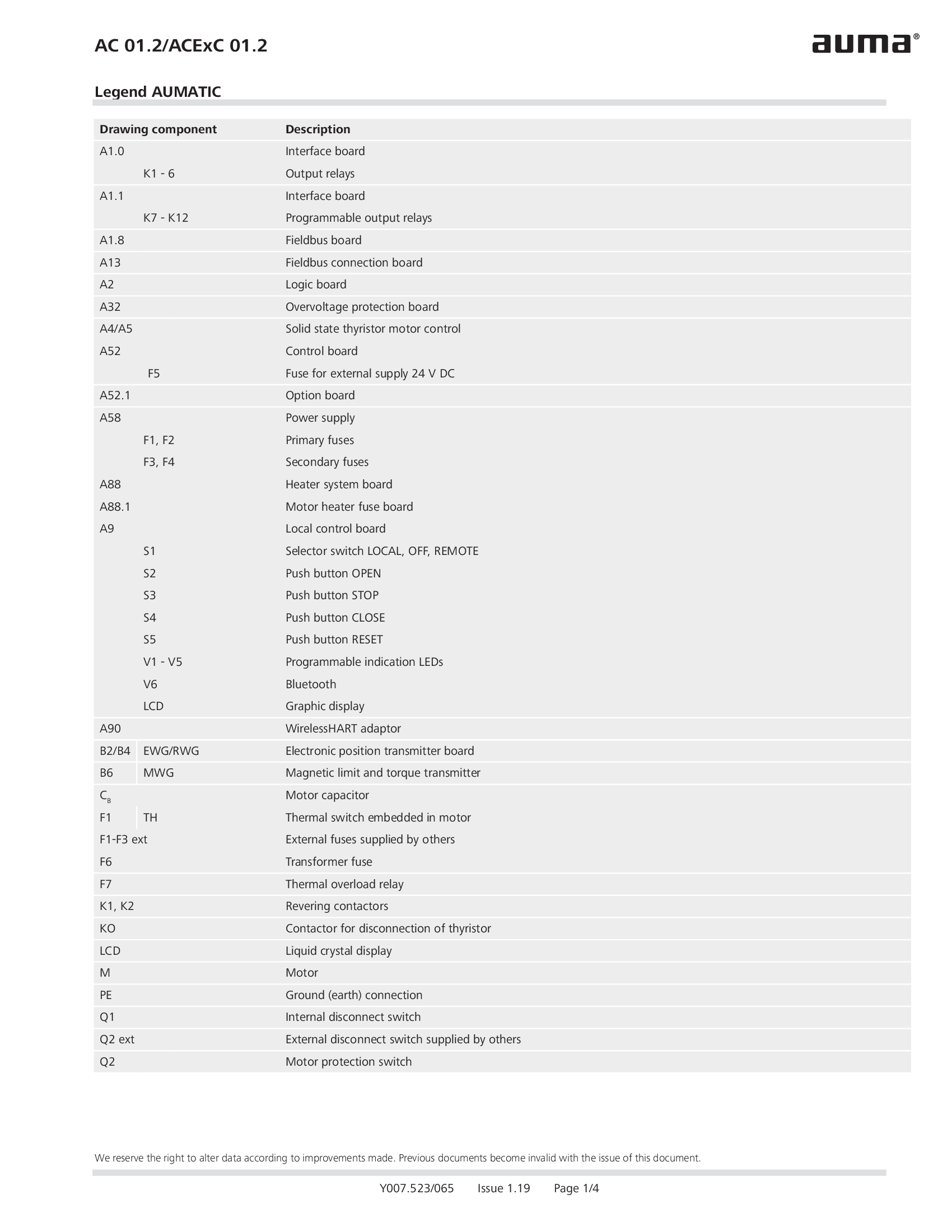
Legend AC 01.2/ACEx 01.2
Wiring diagram

Legend AC 01.2/ACEx 01.2, AC 01.2-SIL/ACExC 01.2-SIL
Wiring diagram
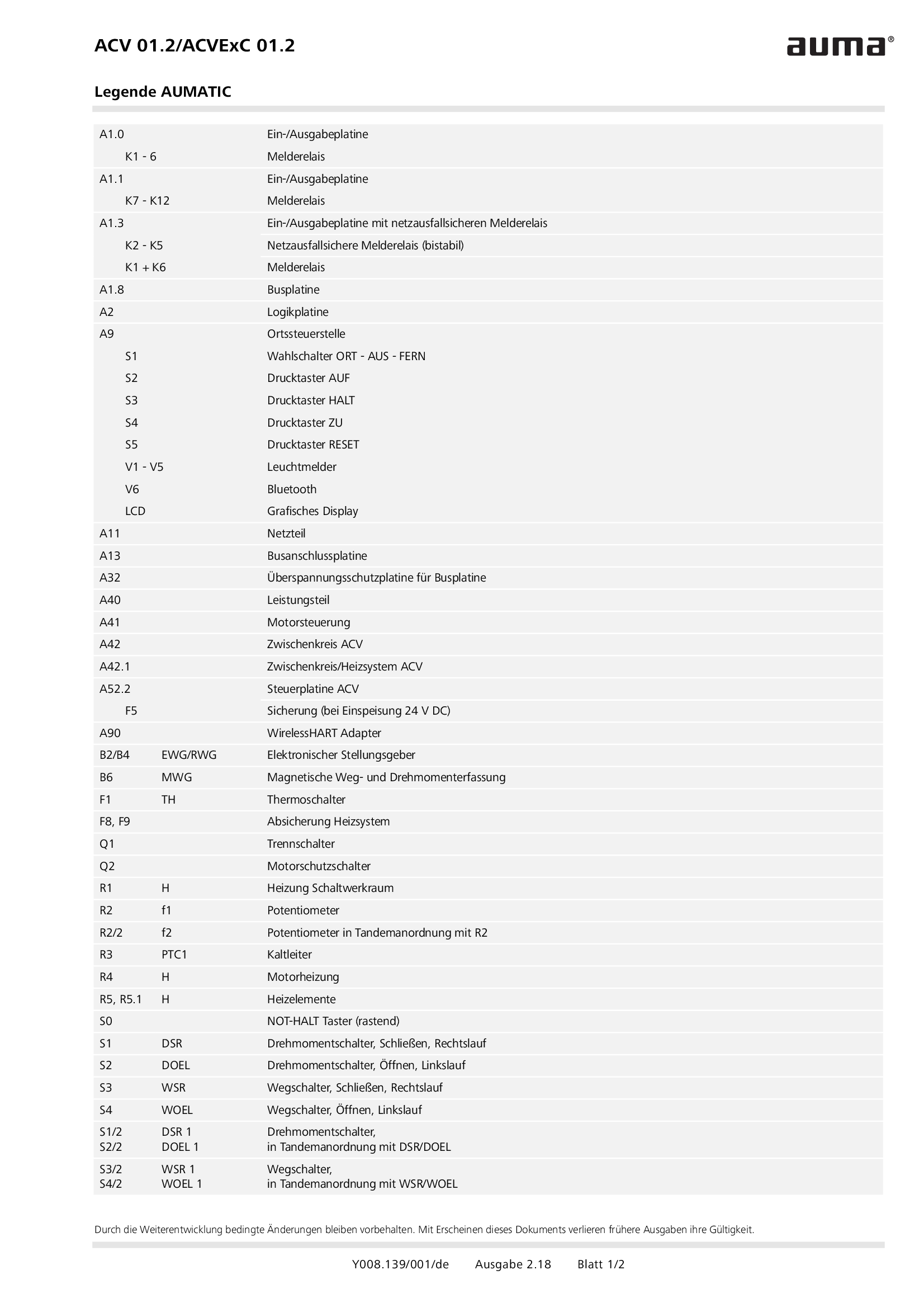
Legend ACV 01.2/ACVEx 01.2
Wiring diagram

PROFOX PF-Q, PF-M, Profibus DP, with analogue input
Wiring diagram

PROFOX PF-Q, PF-M, Profibus DP, without analogue input
Wiring diagram

PROFOX PF-Q, PF-M, Profibus DP, without analogue input, direct current, 24 V DC
Wiring diagram

Part-turn actuators SGC/SGCR, Valve actuators SVC/SVCR, Profibus DP
Wiring diagram

Part-turn actuators SGM/SGMR, Valve actuators SVM/SVMR, Profibus DP
Wiring diagram
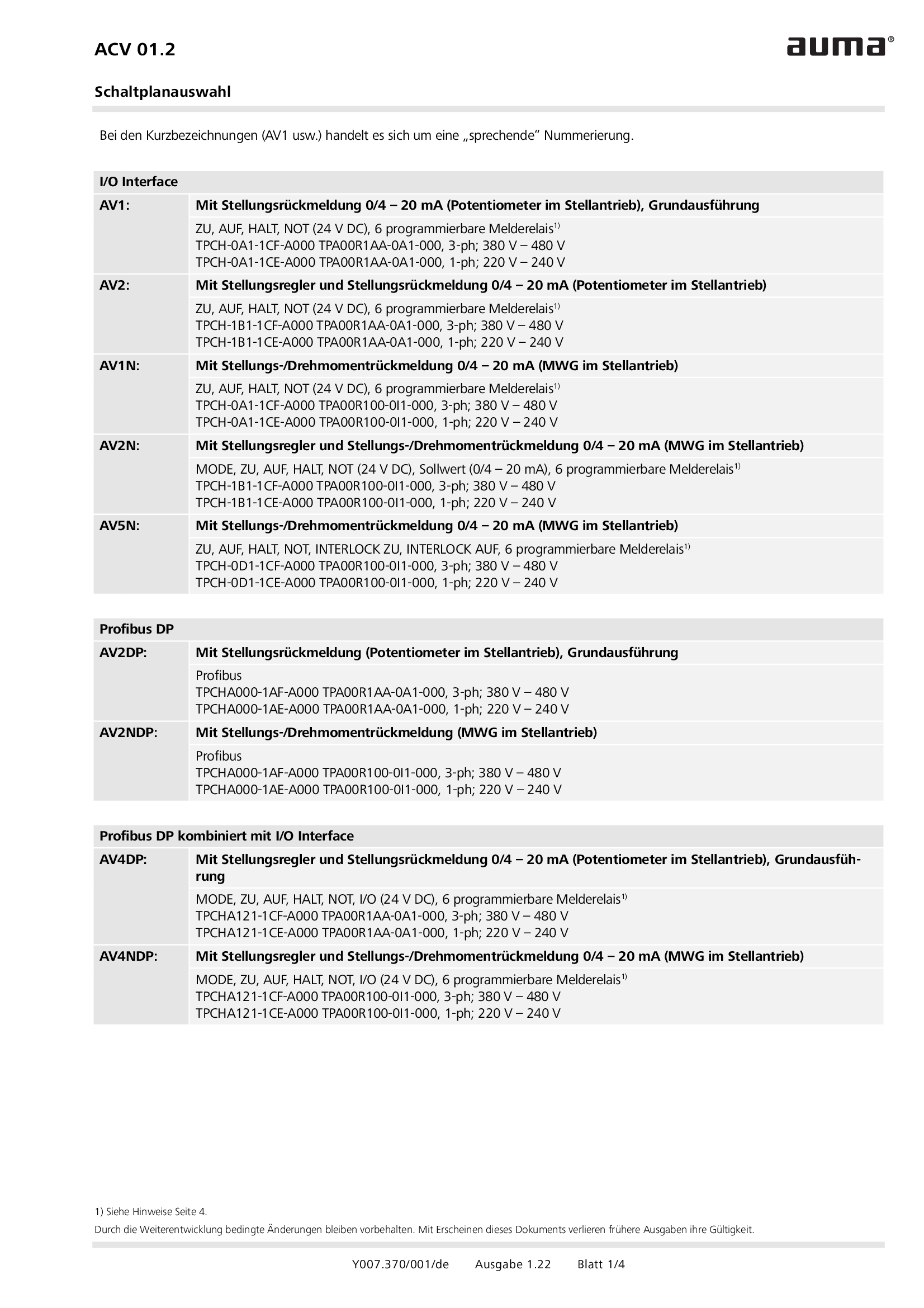
Selection for wiring diagram for ACV 01.2
Wiring diagram
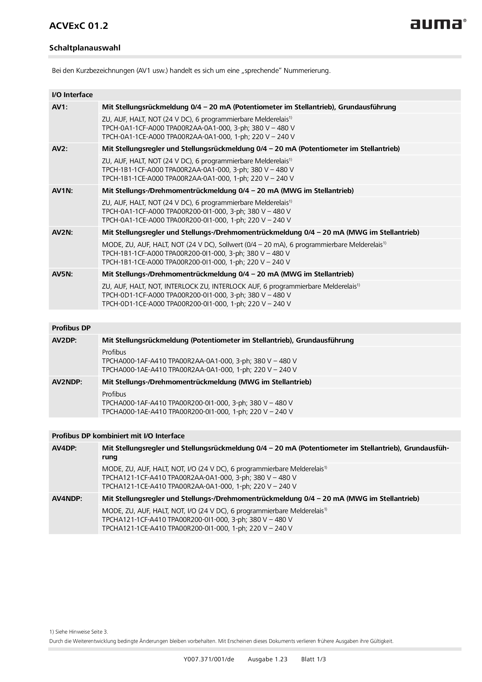
Selection for wiring diagram for ACVExC 01.2
Wiring diagram
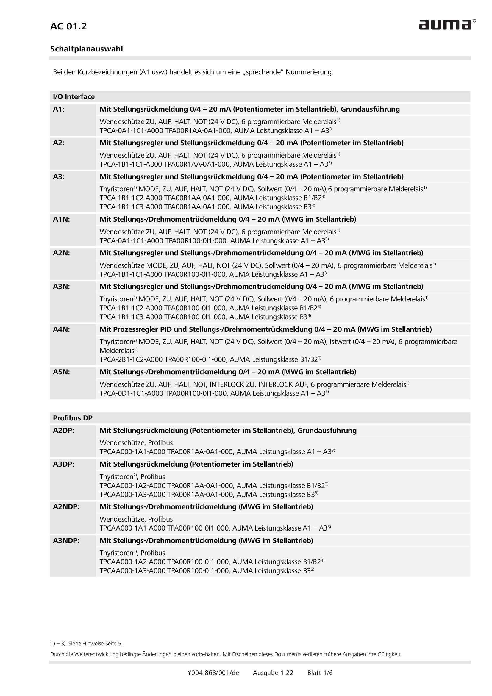
Selection for wiring diagram for AUMATIC AC 01.2
Wiring diagram
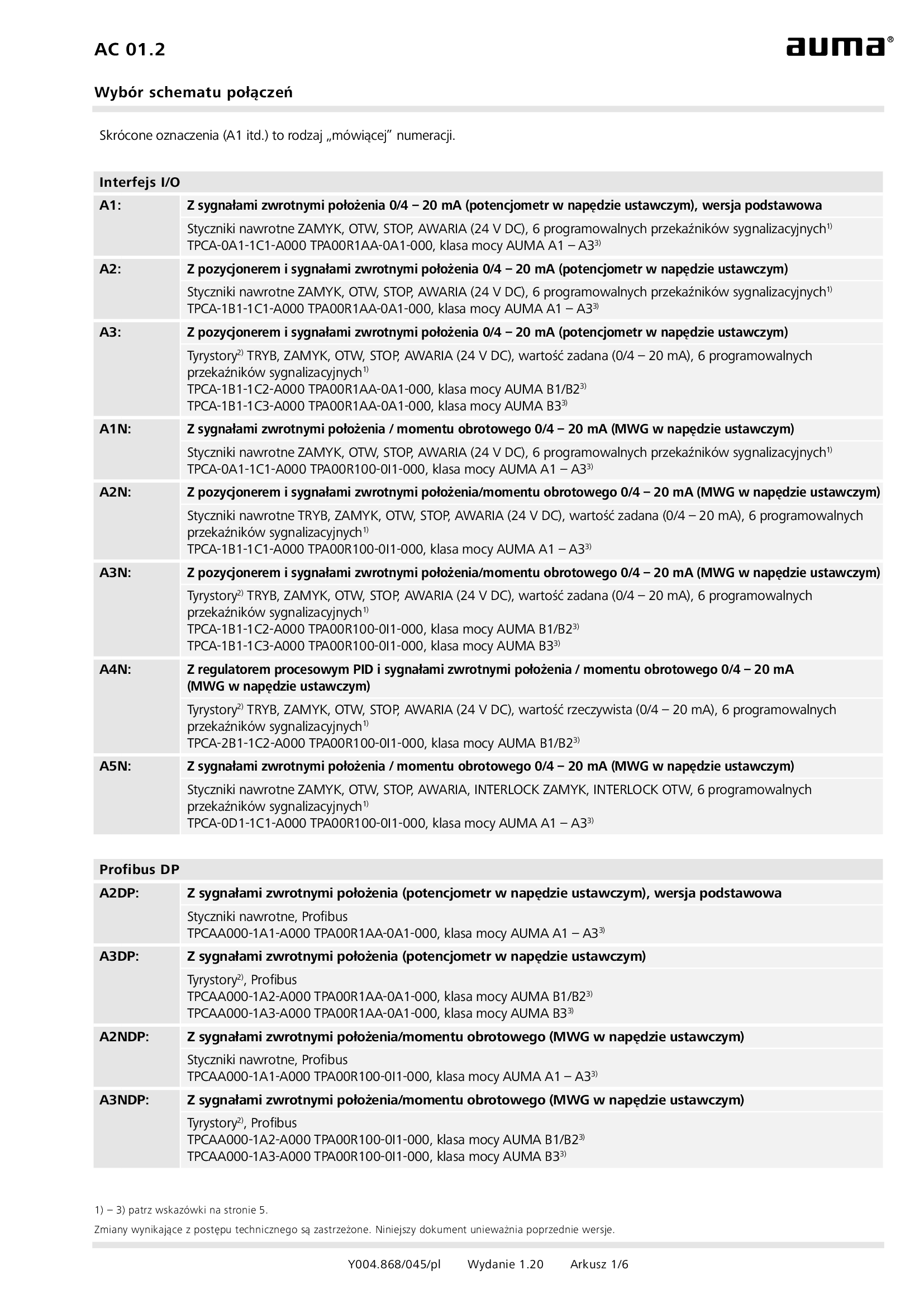
Selection for wiring diagram for AUMATIC AC 01.2/ACExC 01.2
Wiring diagram
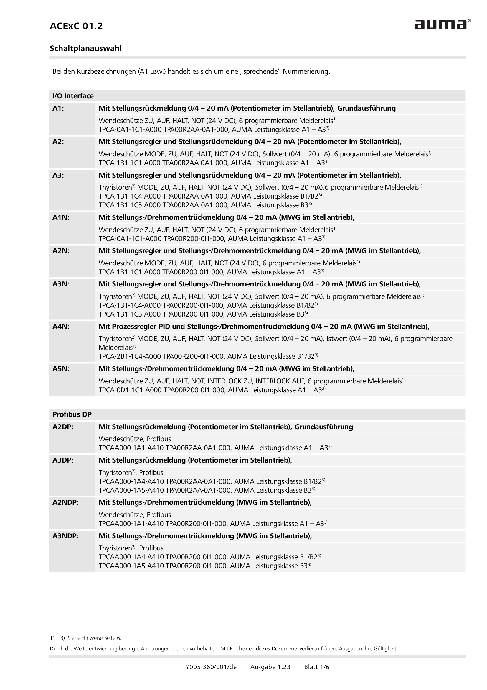
Selection for wiring diagram for AUMATIC ACExC 01.2
Wiring diagram
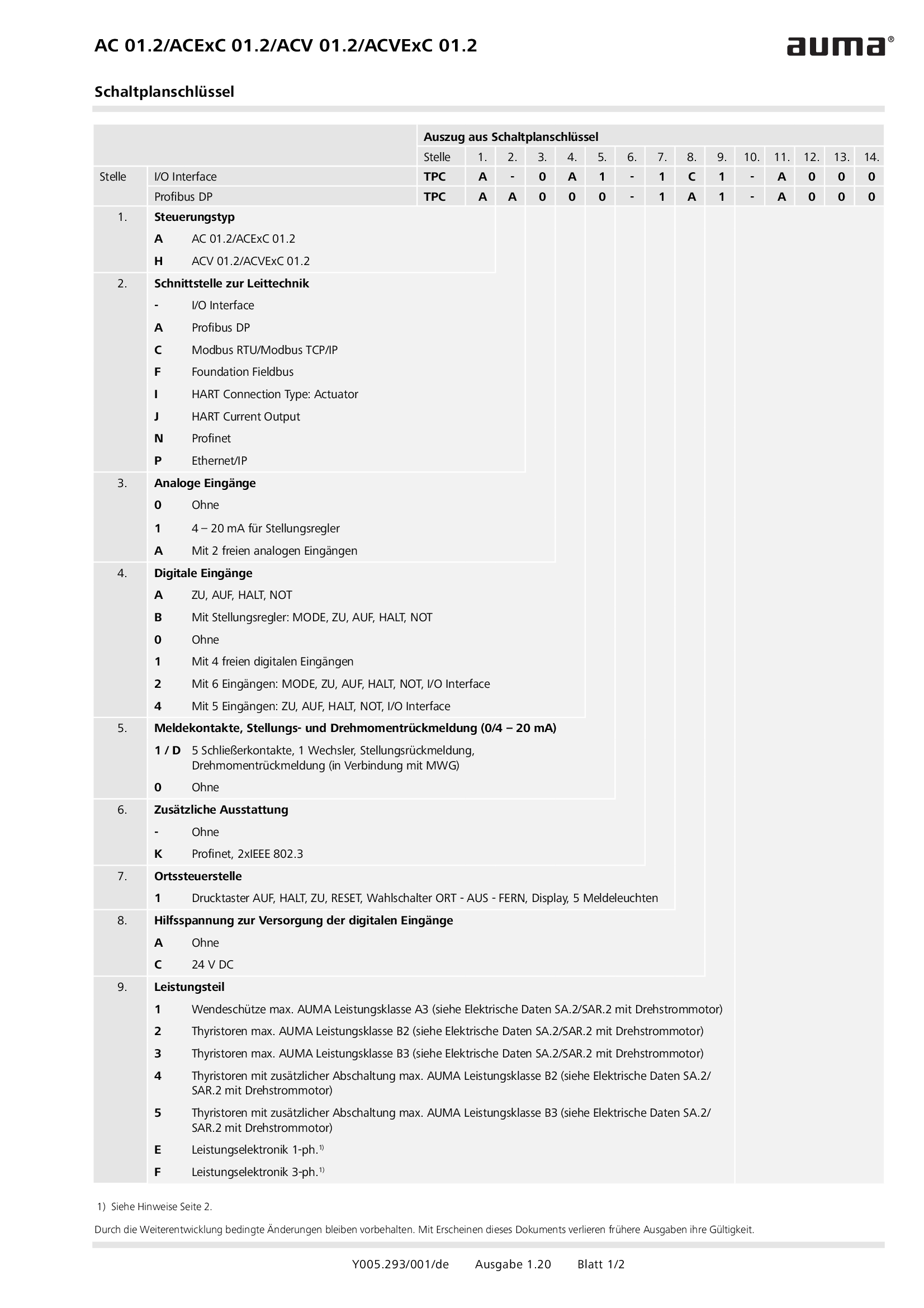
Wiring diagram code for AC 01.2/ACExC 01.2/ACV 01.2/ACVExC 01.2
Wiring diagram


