Resultados de búsqueda para
"Supplement GST.1 Transport"
Operation instructions
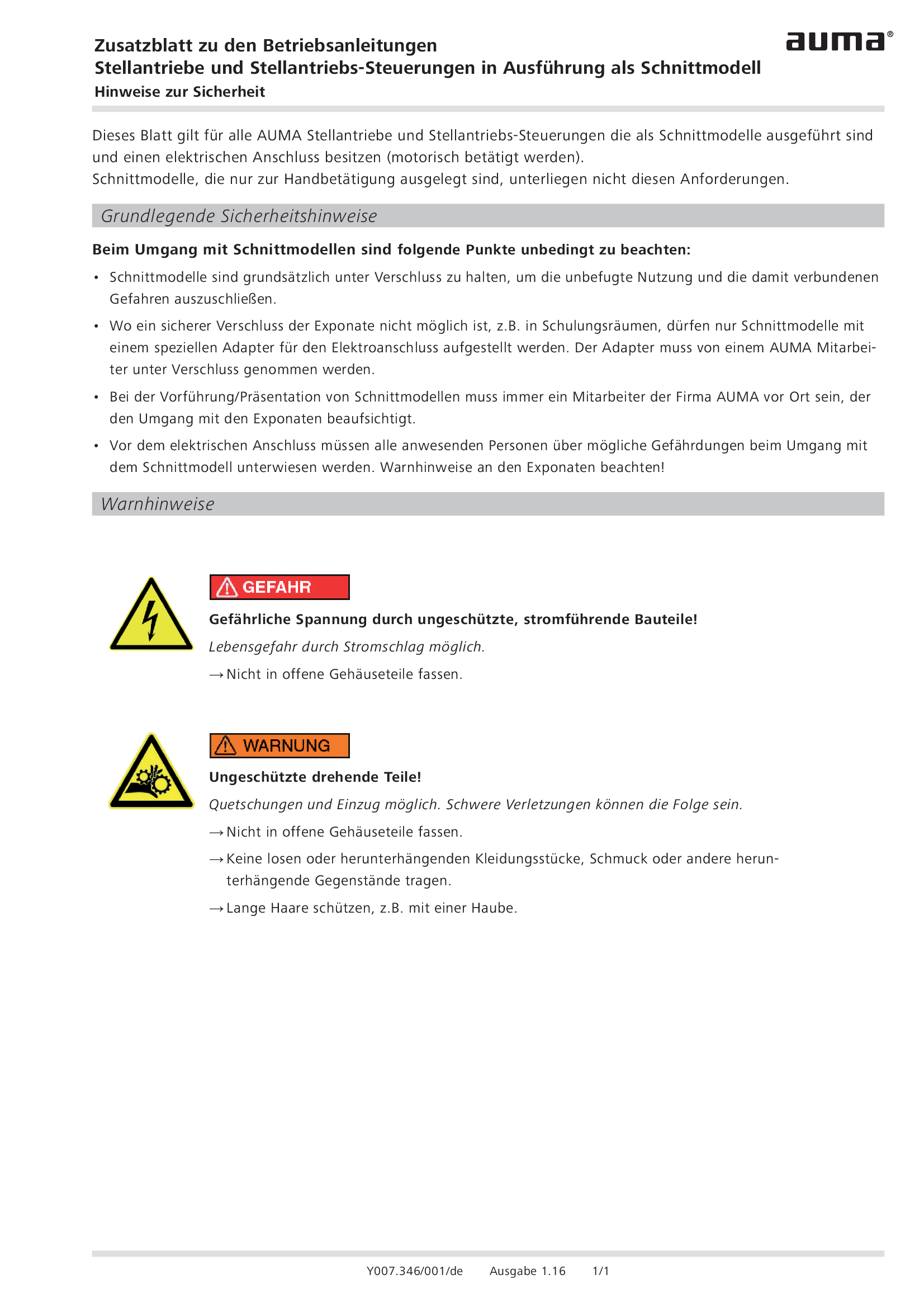
Supplement actuators and actuator controls in version cut-away models
Operation instructions
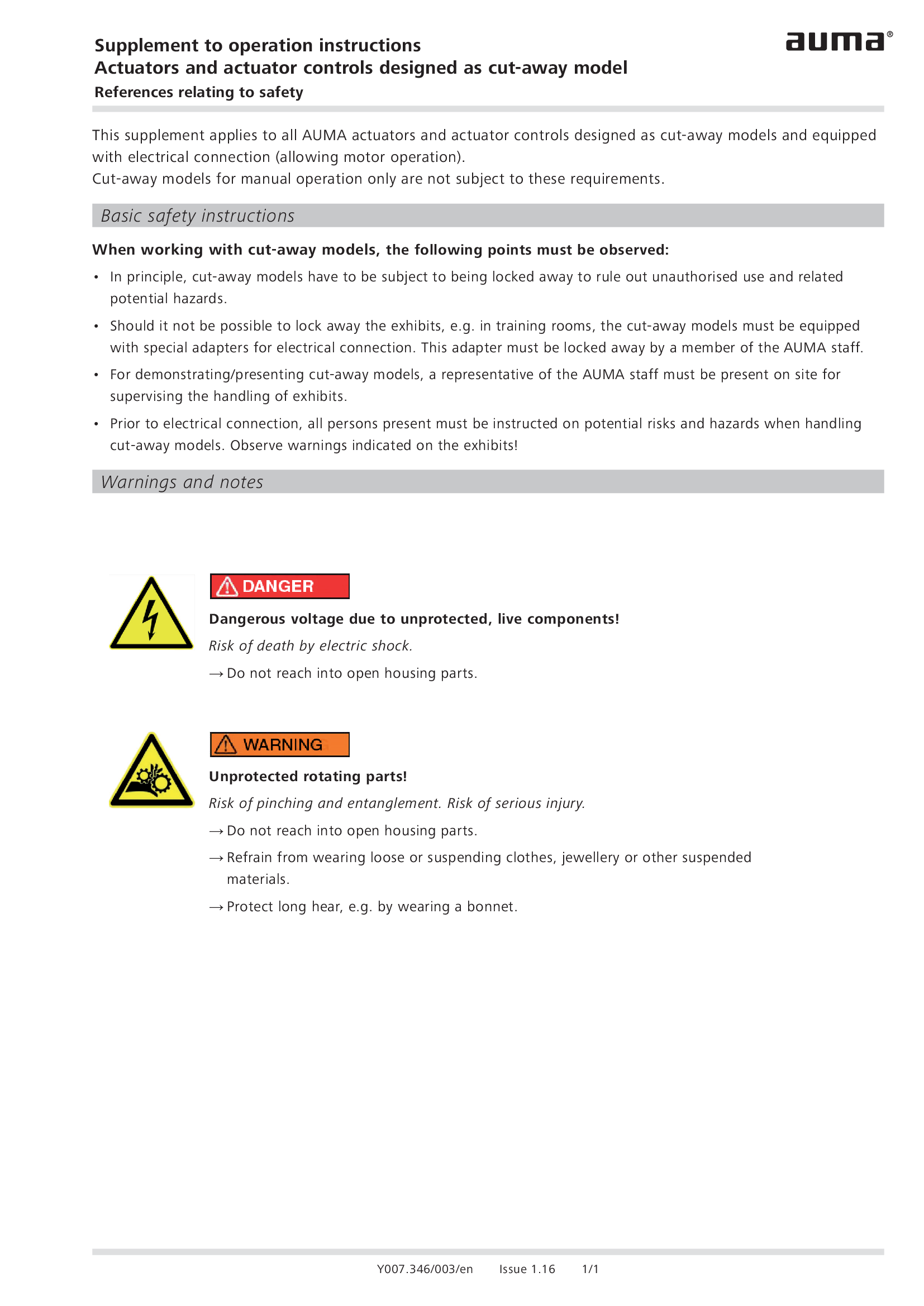
Supplement actuators and actuator controls in version cut-away models
Operation instructions
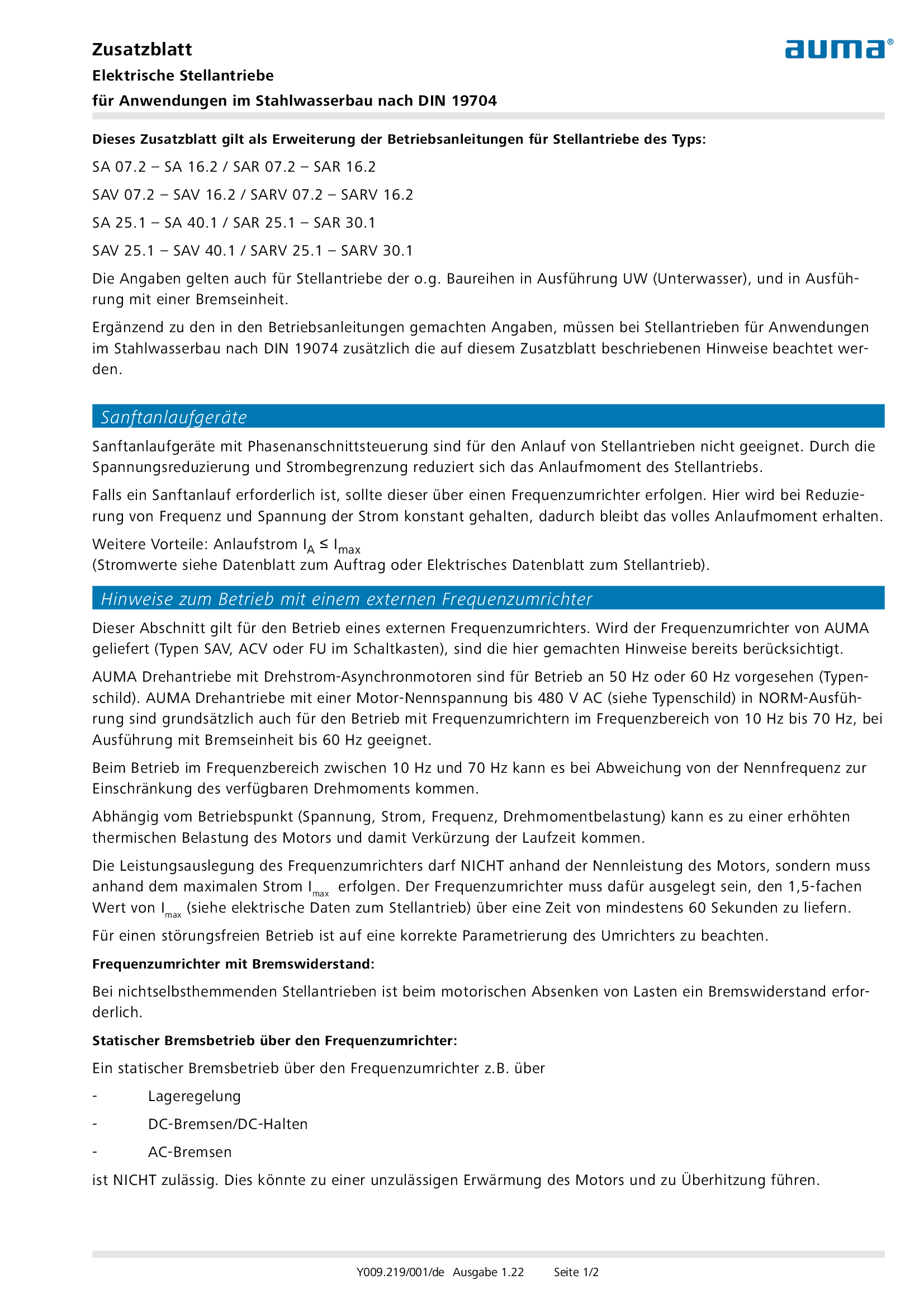
Supplement electrical actuators ffor applications in hydraulic steel structures in accordance with DIN 19704
Operation instructions
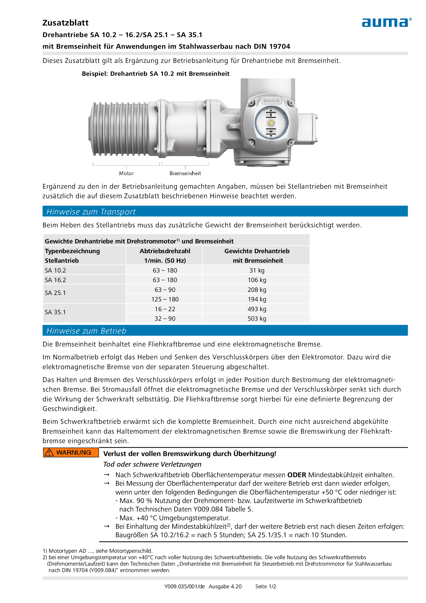
Supplement multi-turn actuators SA 10.2 – 16.2/SA 25.1 – SA 35.1 with break unit for civil engineering constructions for water applications according DIN 19704
Operation instructions
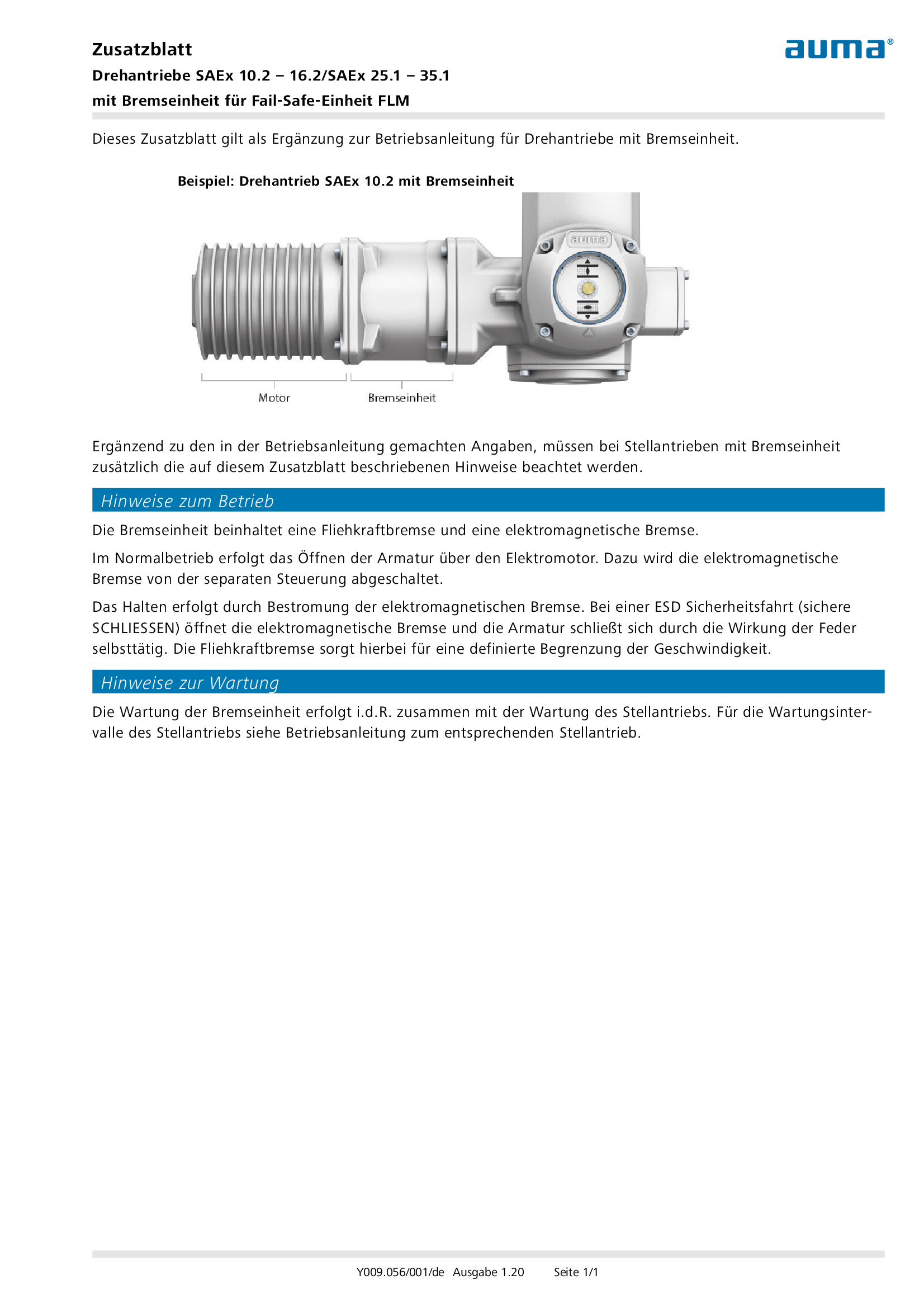
Supplement multi-turn actuators SAEx 10.2 – 16.2/SAEx 25.1 – 35.1 with break unit for Fail-Safe-Unit FLM
Operation instructions

Supplement output drive A/AF/AG/AK transport
Operation instructions
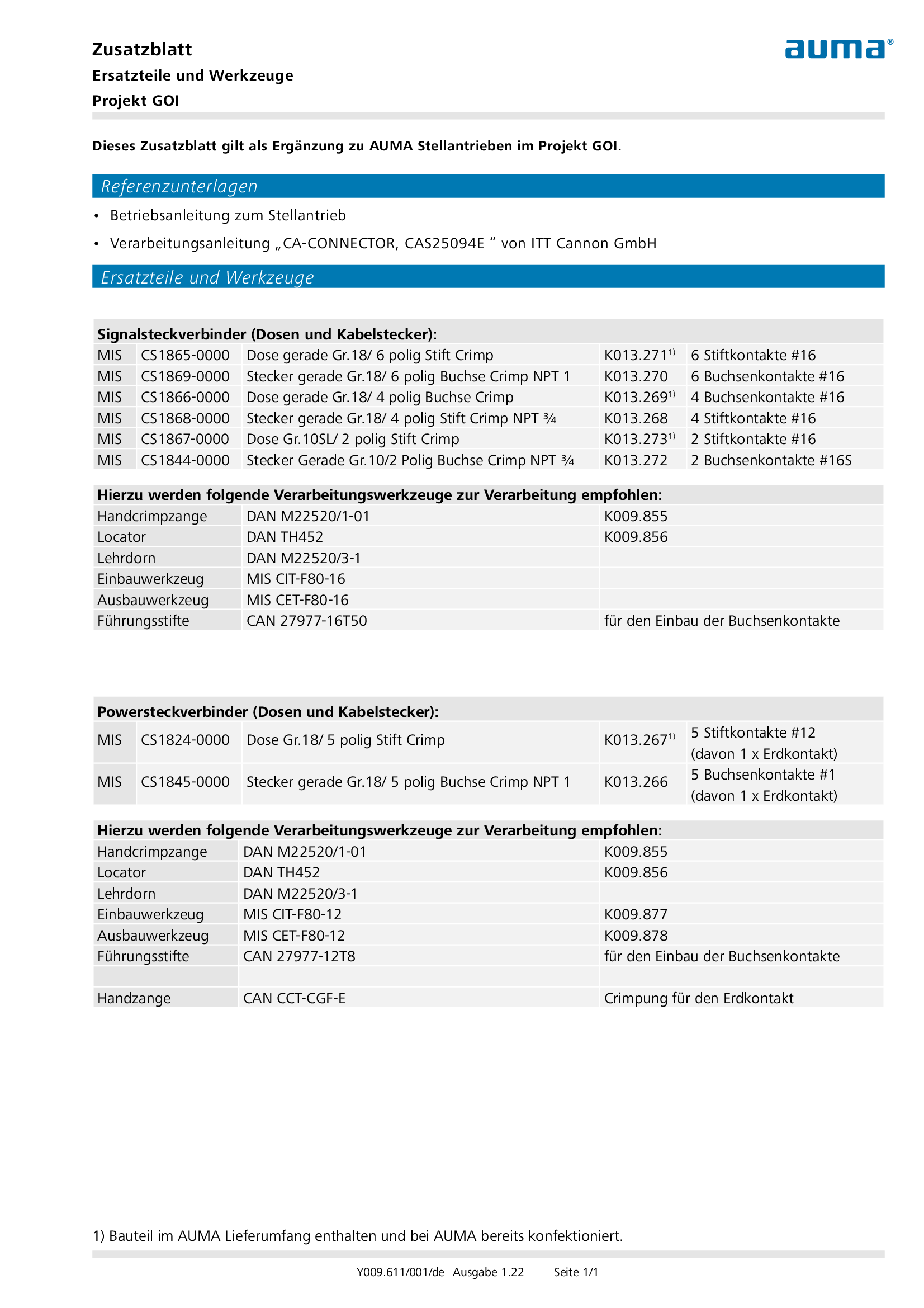
Supplement spare parts and tools project GOI
Operation instructions
Product certificate

Fieldbus Device Registration for AC and ACExC (Rev. 1)
Product certificate

RS Certificate for GST, GK and GW
Product certificate
Short instructions
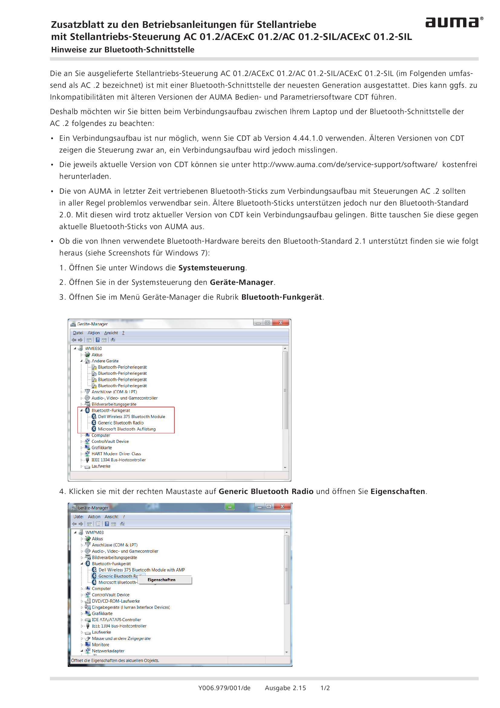
Supplement AC 01.2/ACExC 01.2/AC 01.2-SIL/ACExC 01.2-SIL Bluetooth interface
Short instructions
Spare parts list
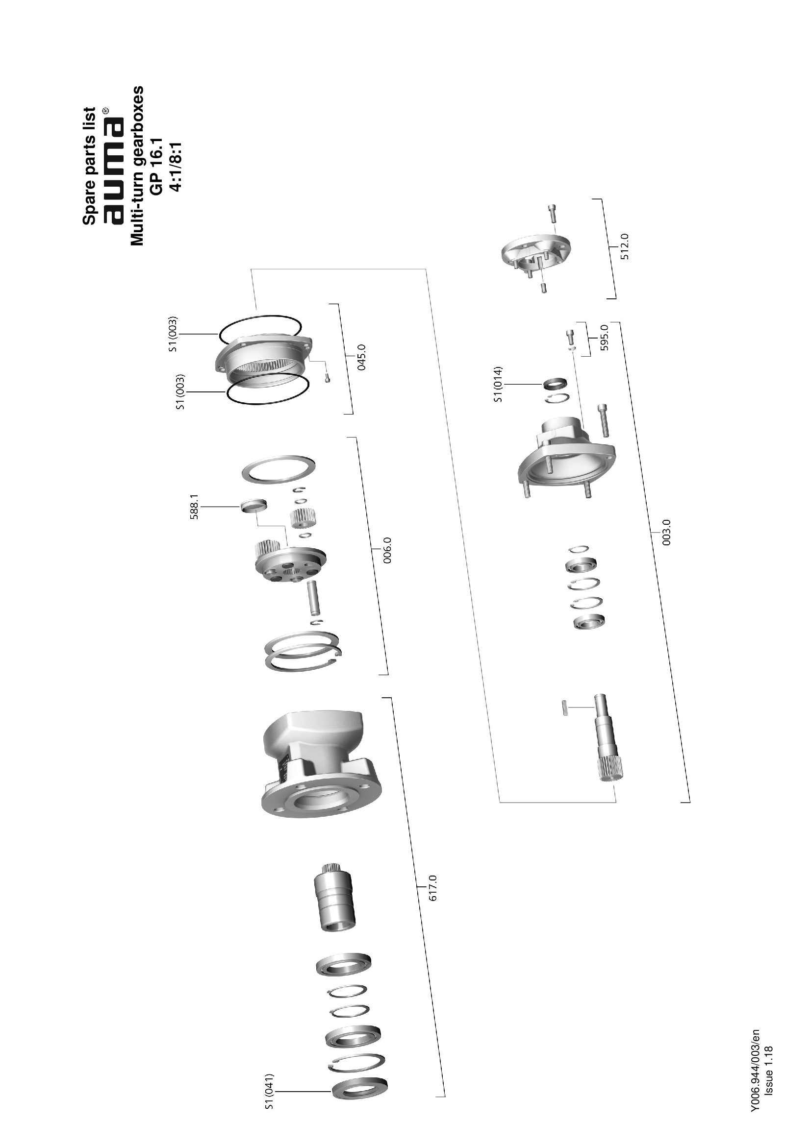
Multi-tun gearbox GP 16.1, 4:1/8:1
Spare parts list

Multi-turn gearbox GP 10.1 - 14.1 (2,4:/3:1/4:1)
Spare parts list

Multi-turn gearbox GP 10.1 - 14.1 (2,4:1/3:1/4:1)
Spare parts list
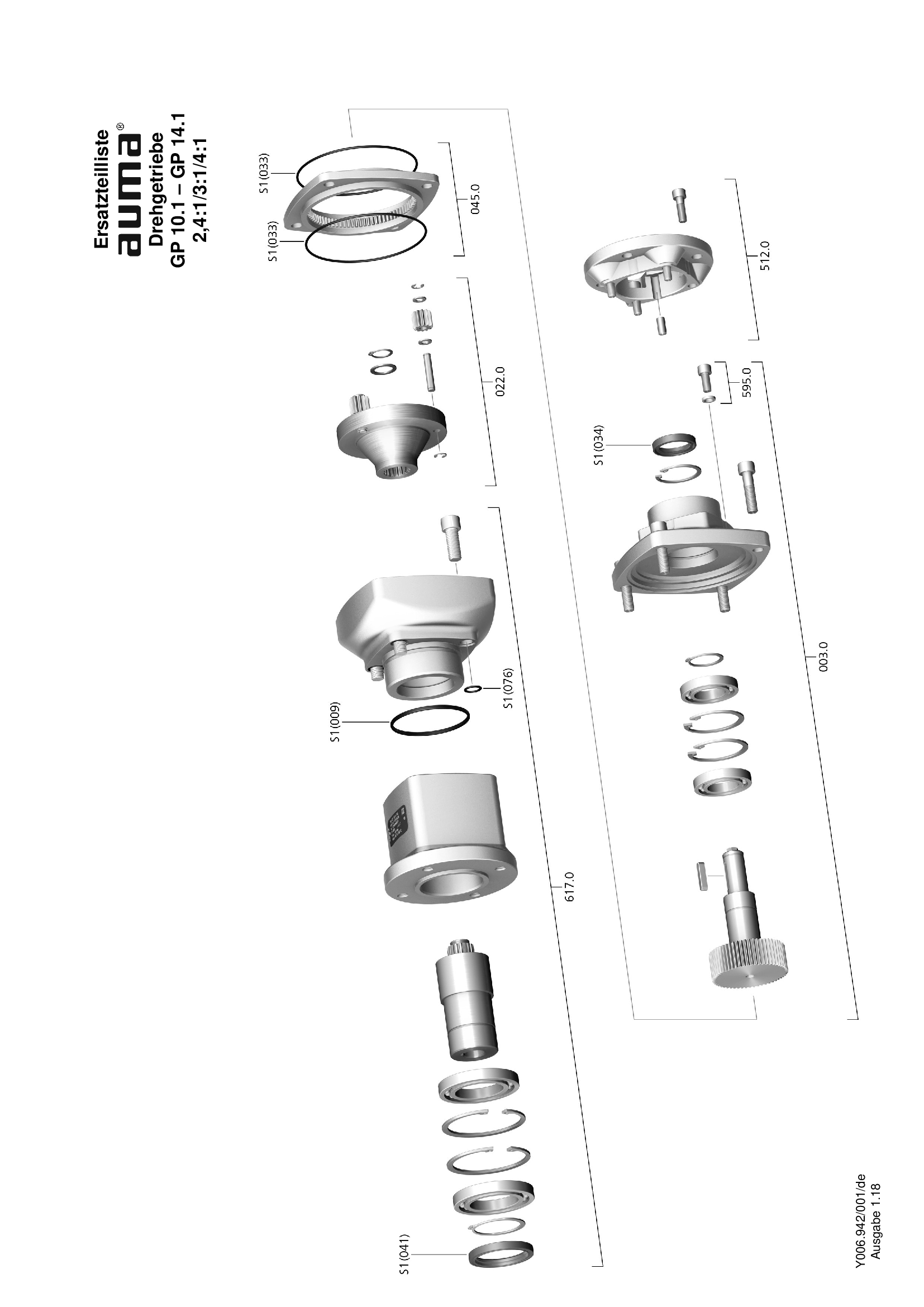
Multi-turn gearbox GP 10.1 - 14.1, 2,4:1/3:1/4:1
Spare parts list

Multi-turn gearbox GP 16.1, 4:1/8:1
Spare parts list

Multi-turn gearbox GP 25.1 - 30.1, 16:1
Spare parts list
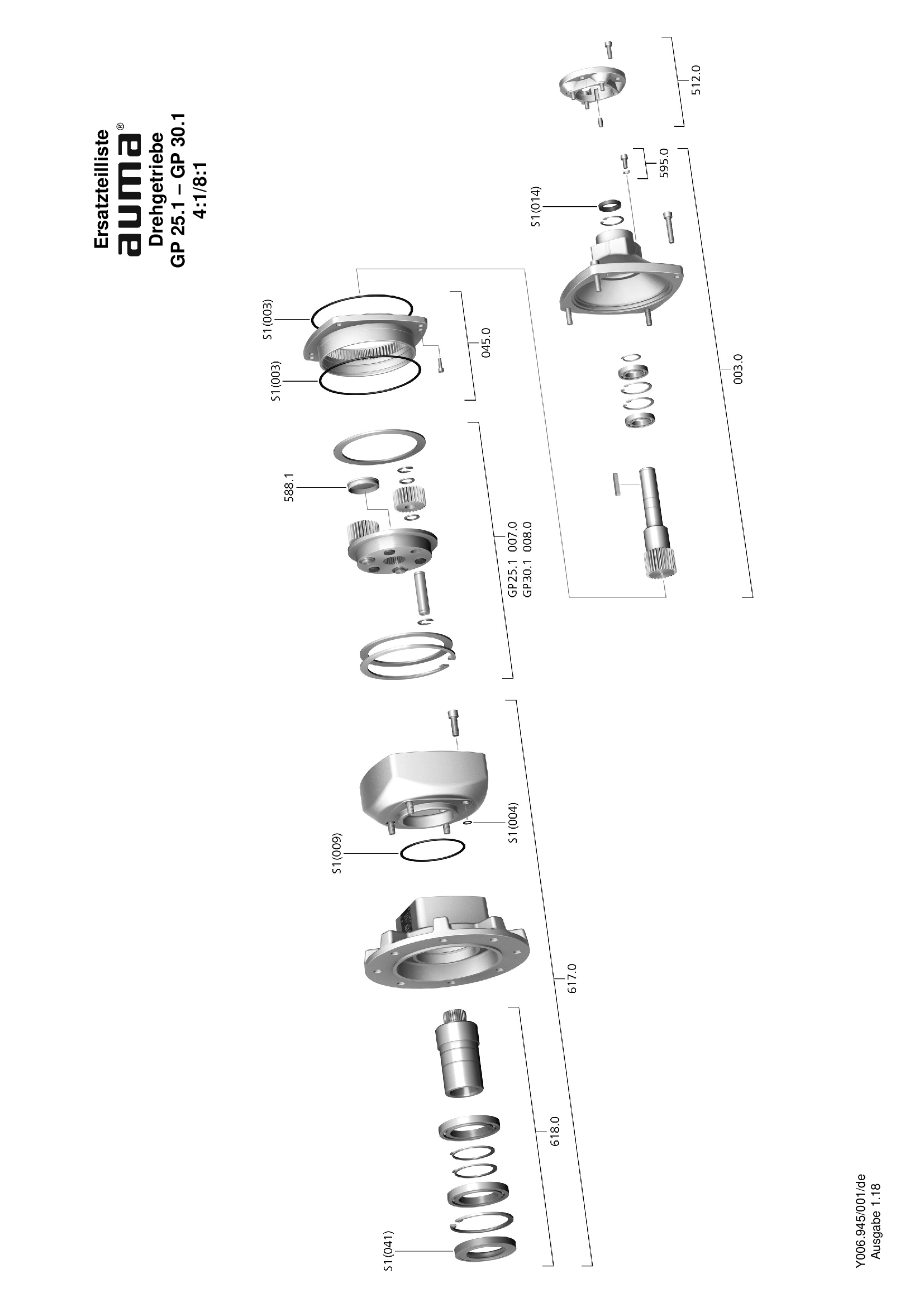
Multi-turn gearbox GP 25.1 - 30.1, 4:1/8:1
Spare parts list

Multi-turn gearbox GST 25.1 – GST 40.1
Spare parts list
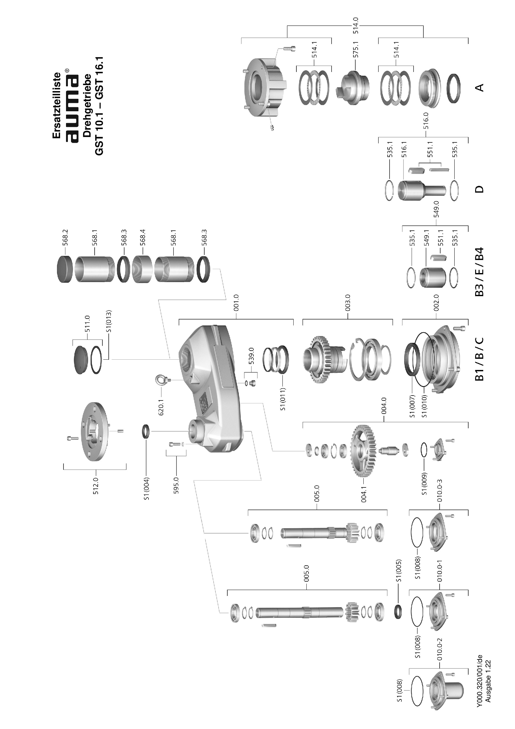
Multi-turn gearboxes GST 10.1 – 16.1
Spare parts list
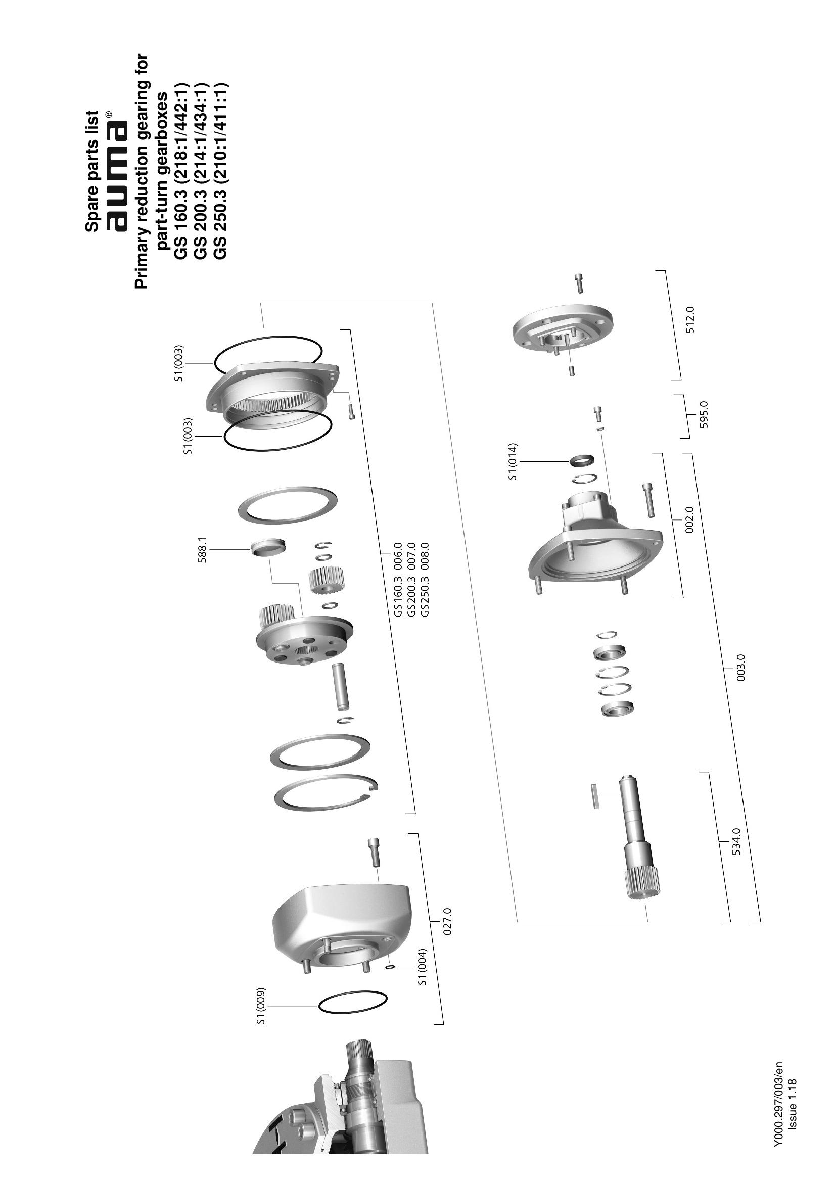
Primary recuction gearing for GS 160.3 - 250.3 (218:1/442:1, 214:1/434:1, 210:1/411:1)
Spare parts list

Primary reduction gearing GS 630.3 (4:1/8:1)
Spare parts list
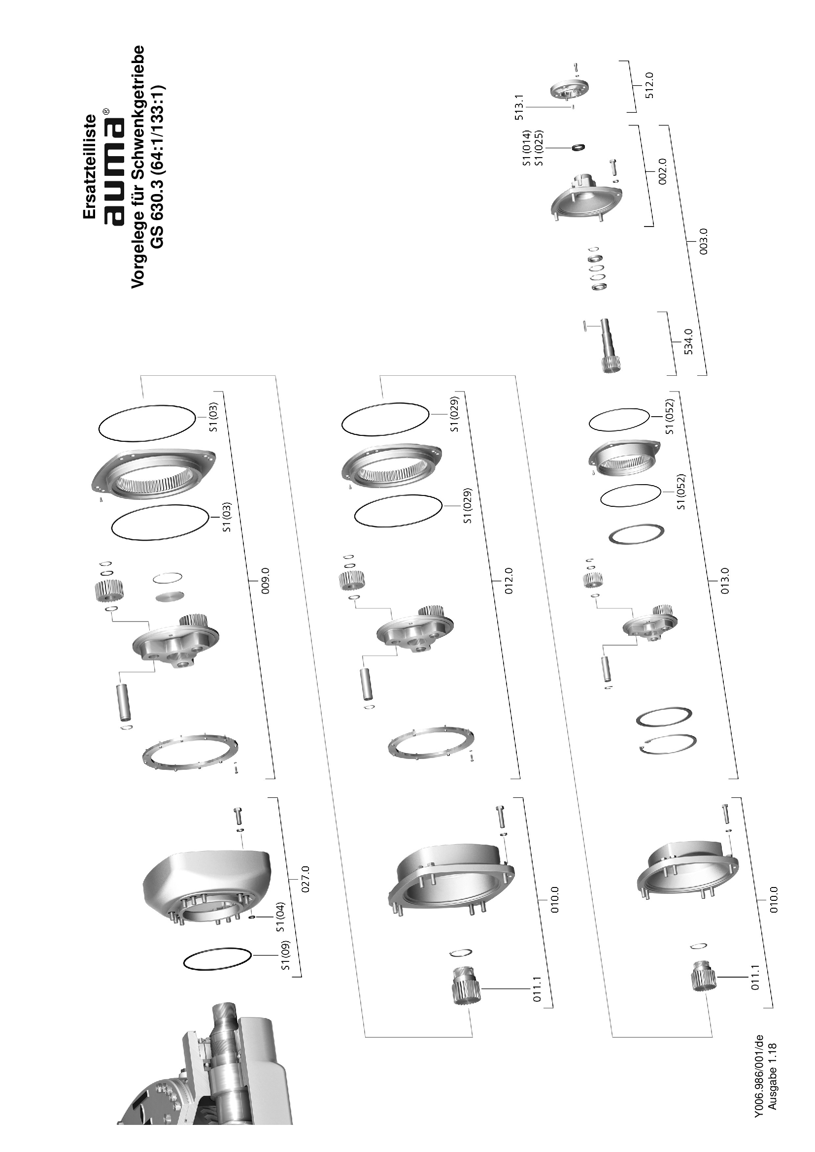
Primary reduction gearing GS 630.3 (64:1/133:1)
Spare parts list
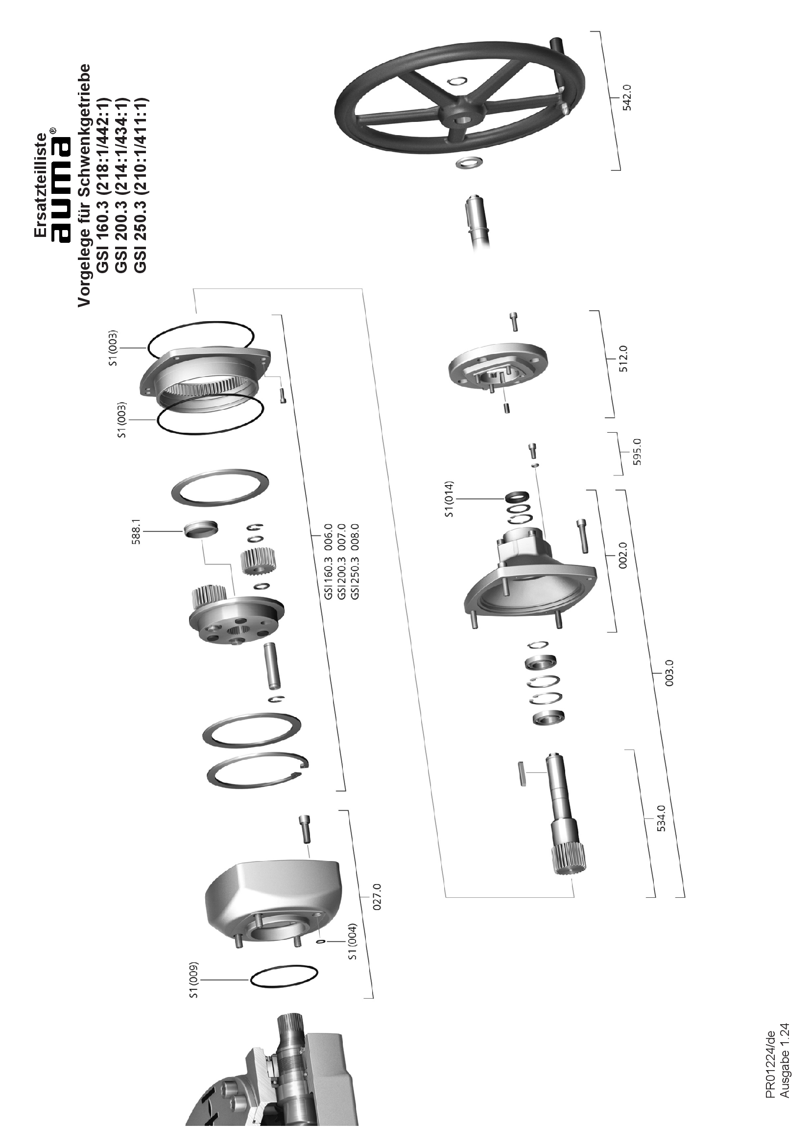
Primary reduction gearing GSI 160.3 – 250.3, 4:1/ 8:1, nuclear power plants
Spare parts list
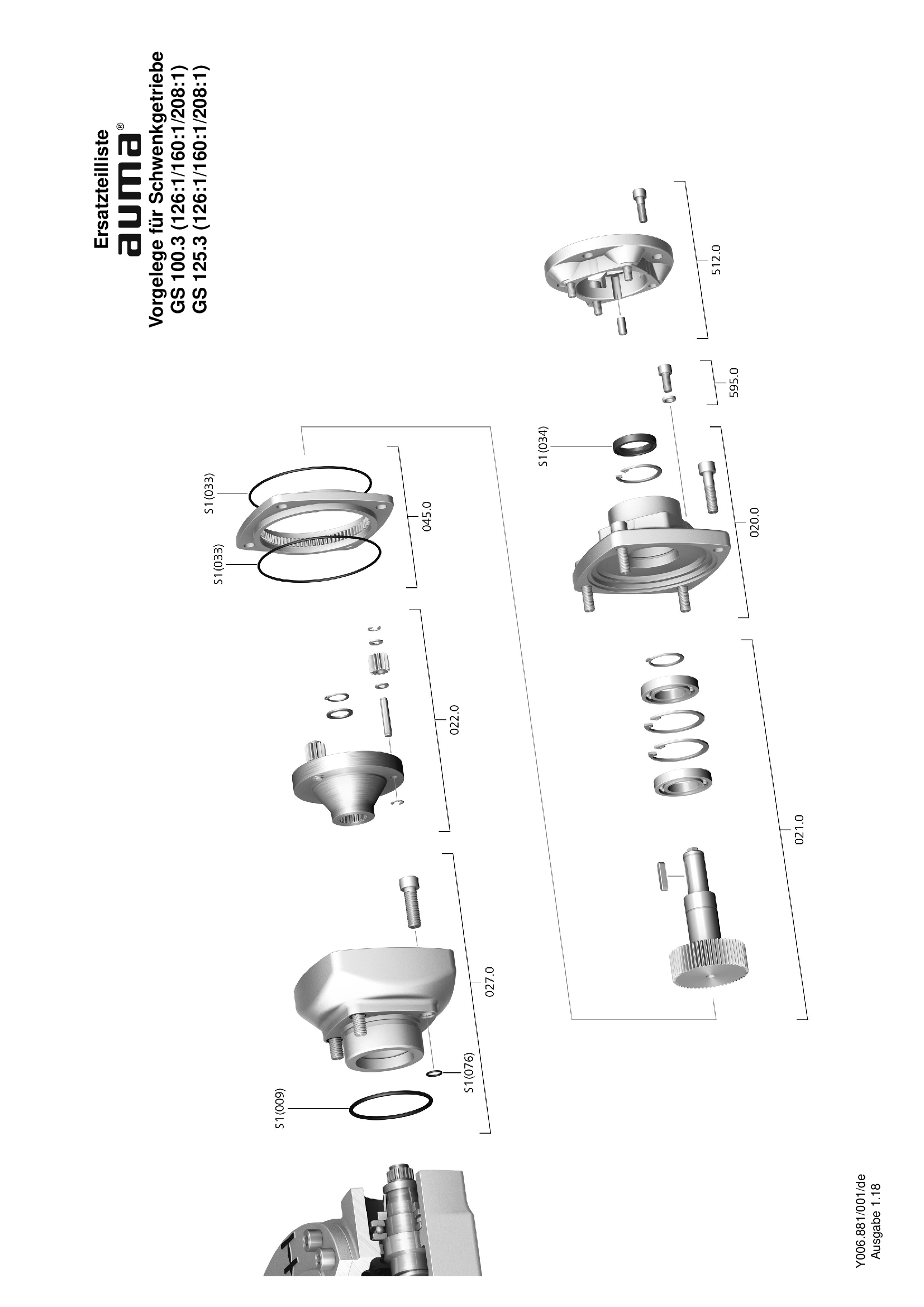
Primary reduction gearing for GS 100.3 - 125.3 (126:1/160:1/208:1)
Spare parts list
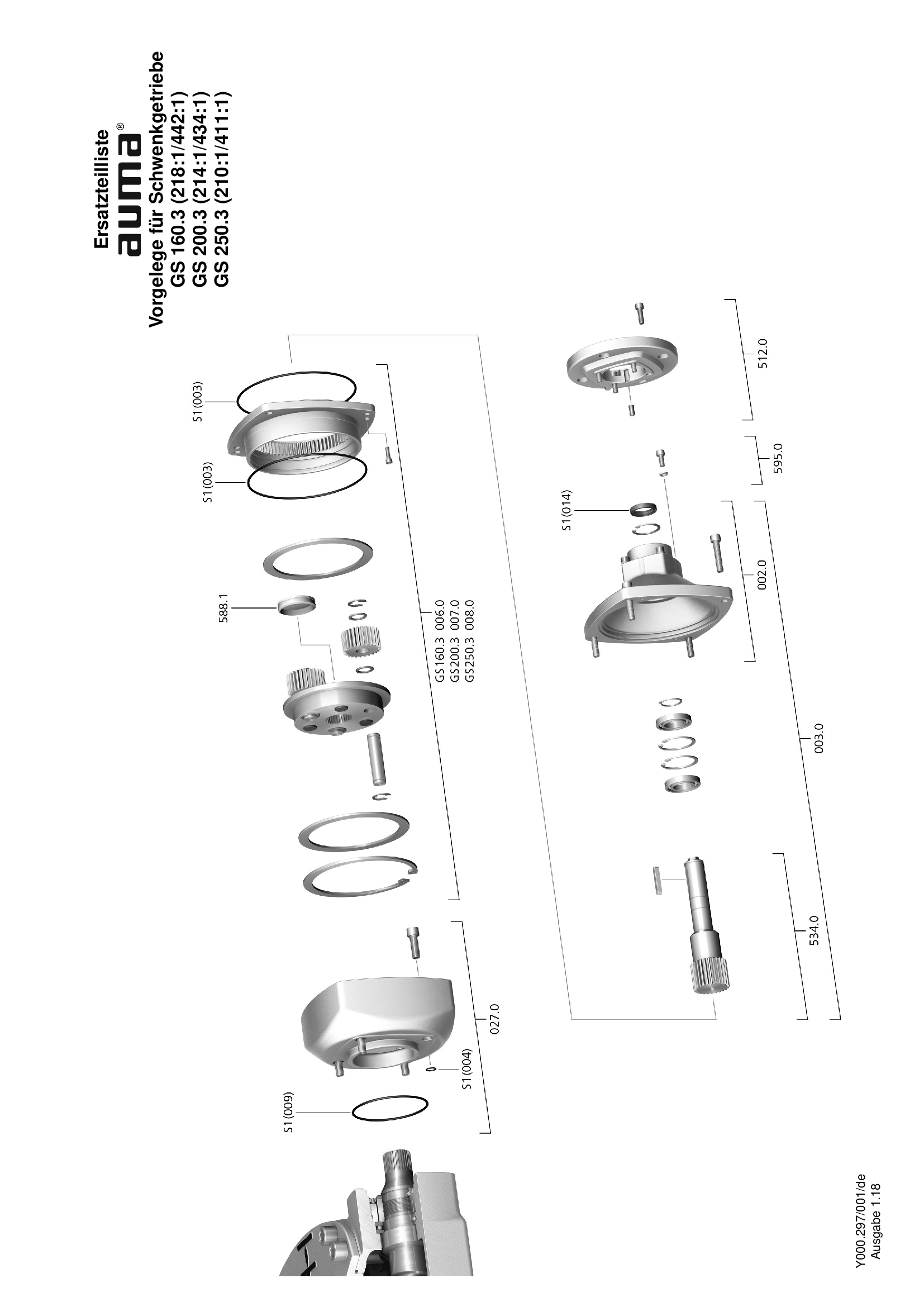
Primary reduction gearing for GS 160.3 - 250.3 (218:1/442:1, 214:1/434:1, 210:1/411:1)
Spare parts list
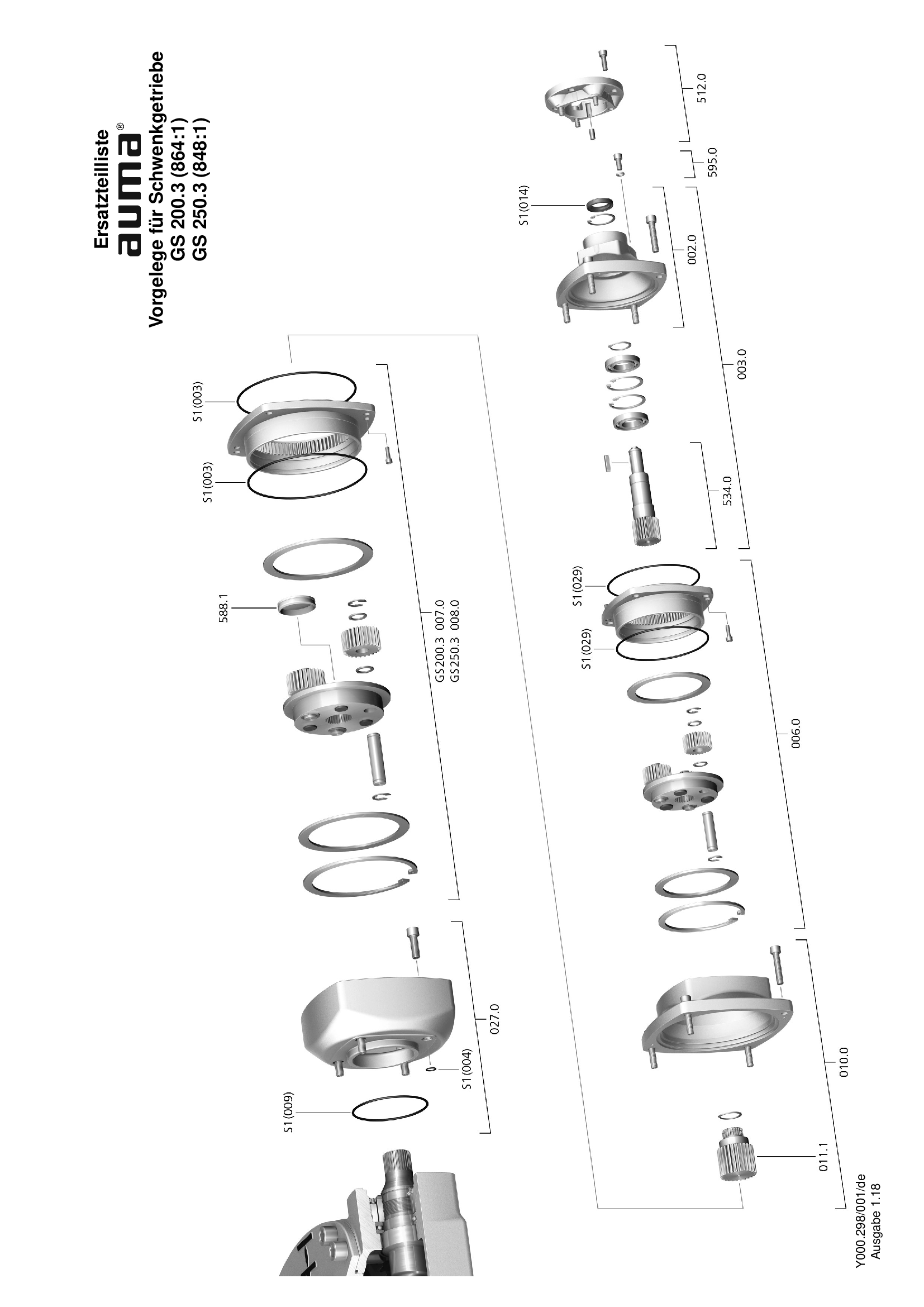
Primary reduction gearing for GS 200.3 - 250.3 (864:1/848:1)
Spare parts list

Primary reduction gearing for GS 630.3 (16:1/32:1)
Spare parts list
Technical data
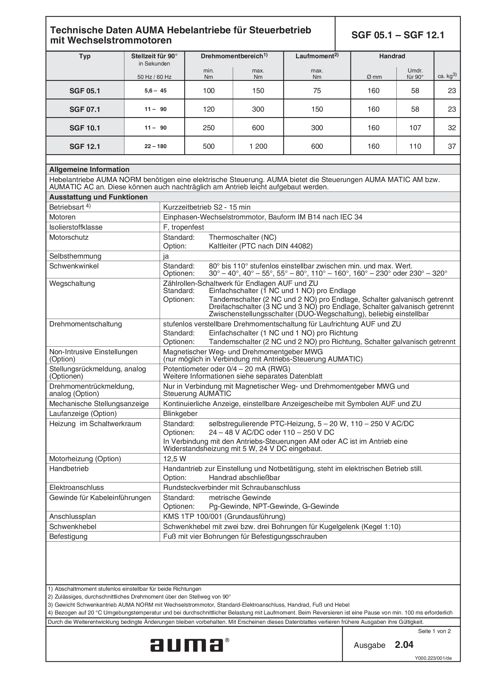
Lever actuators SGF 05.1 - 12.1, open-close duty, 1-phase AC
Technical data
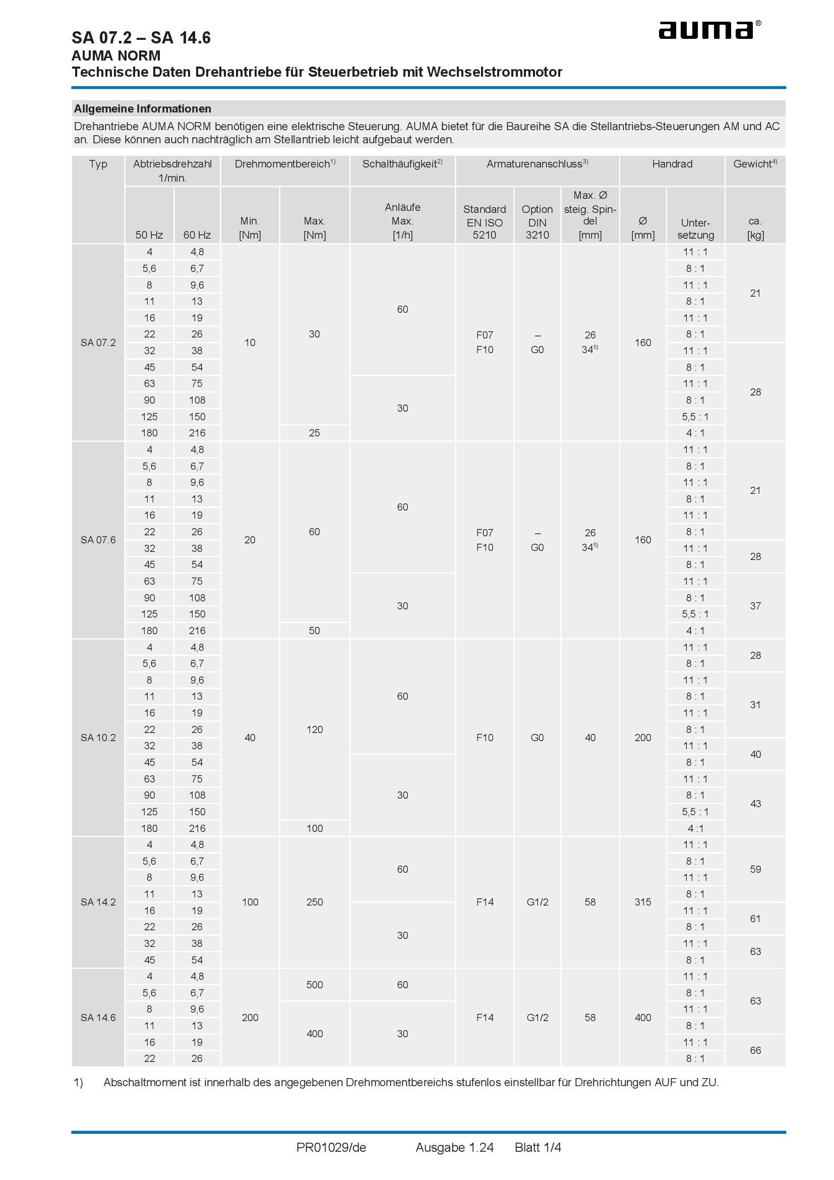
Multi-turn actuators SA 07.2 - 14.6, open-close duty, 1-phase AC
Technical data
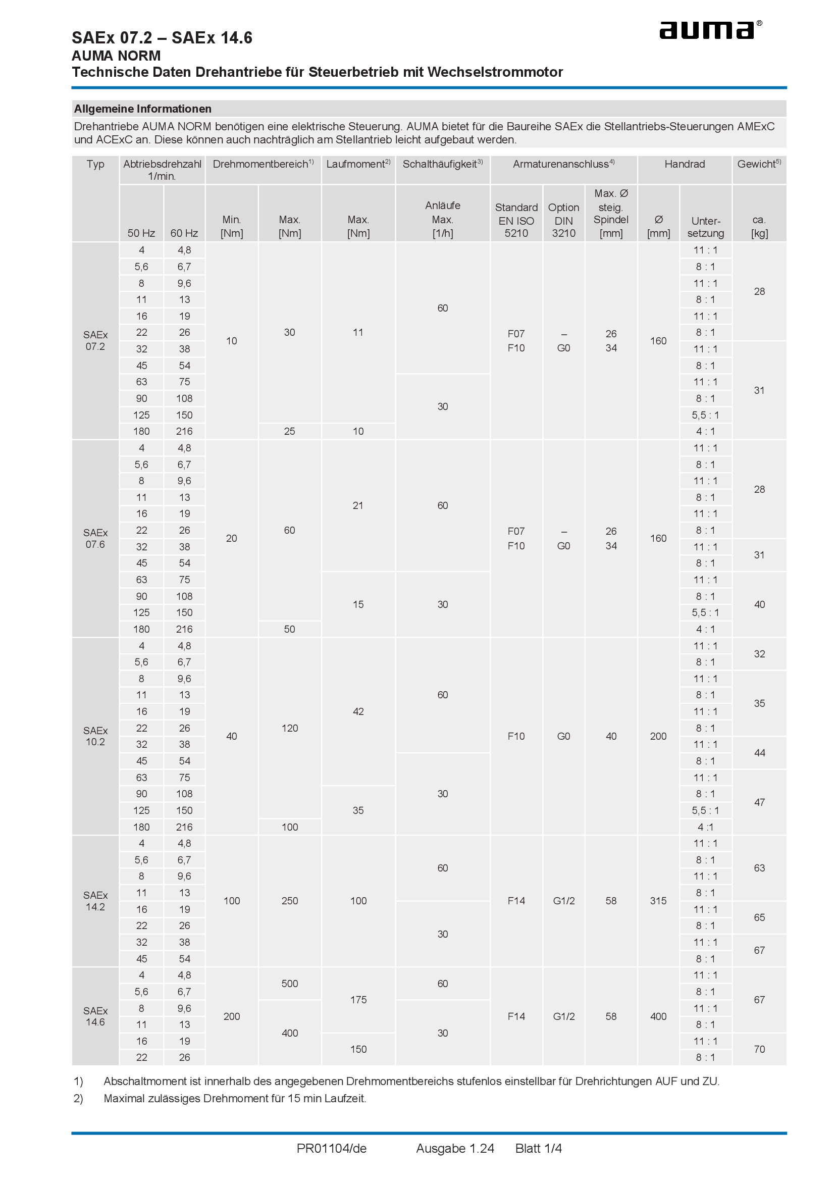
Multi-turn actuators SAEx 07.2 - 14.6, open-close duty, 1-phase AC
Technical data
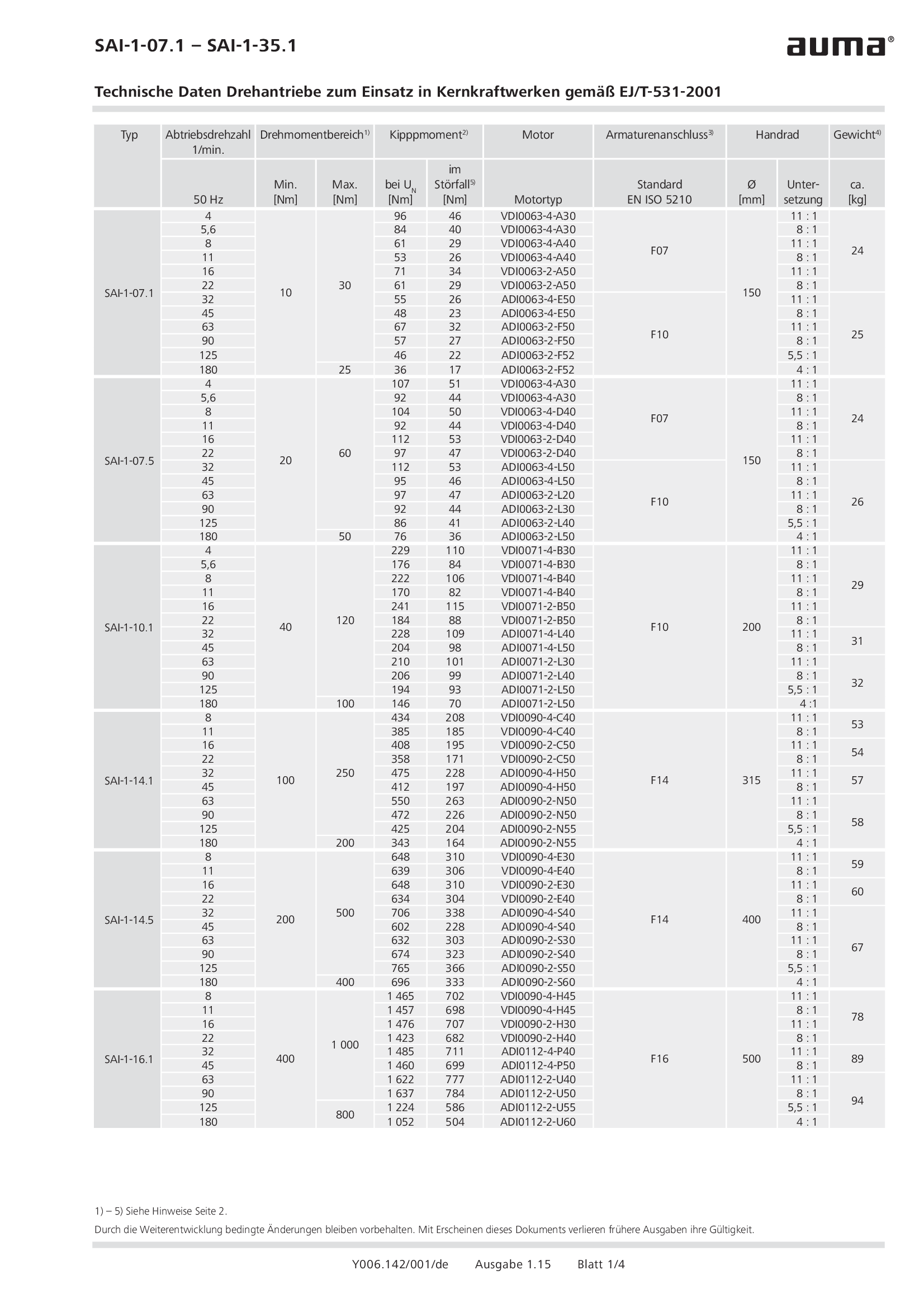
Multi-turn actuators SAI-1-07.1 - 35.1, open-close duty, nuclear power plants, EJ/T-531-2001
Technical data
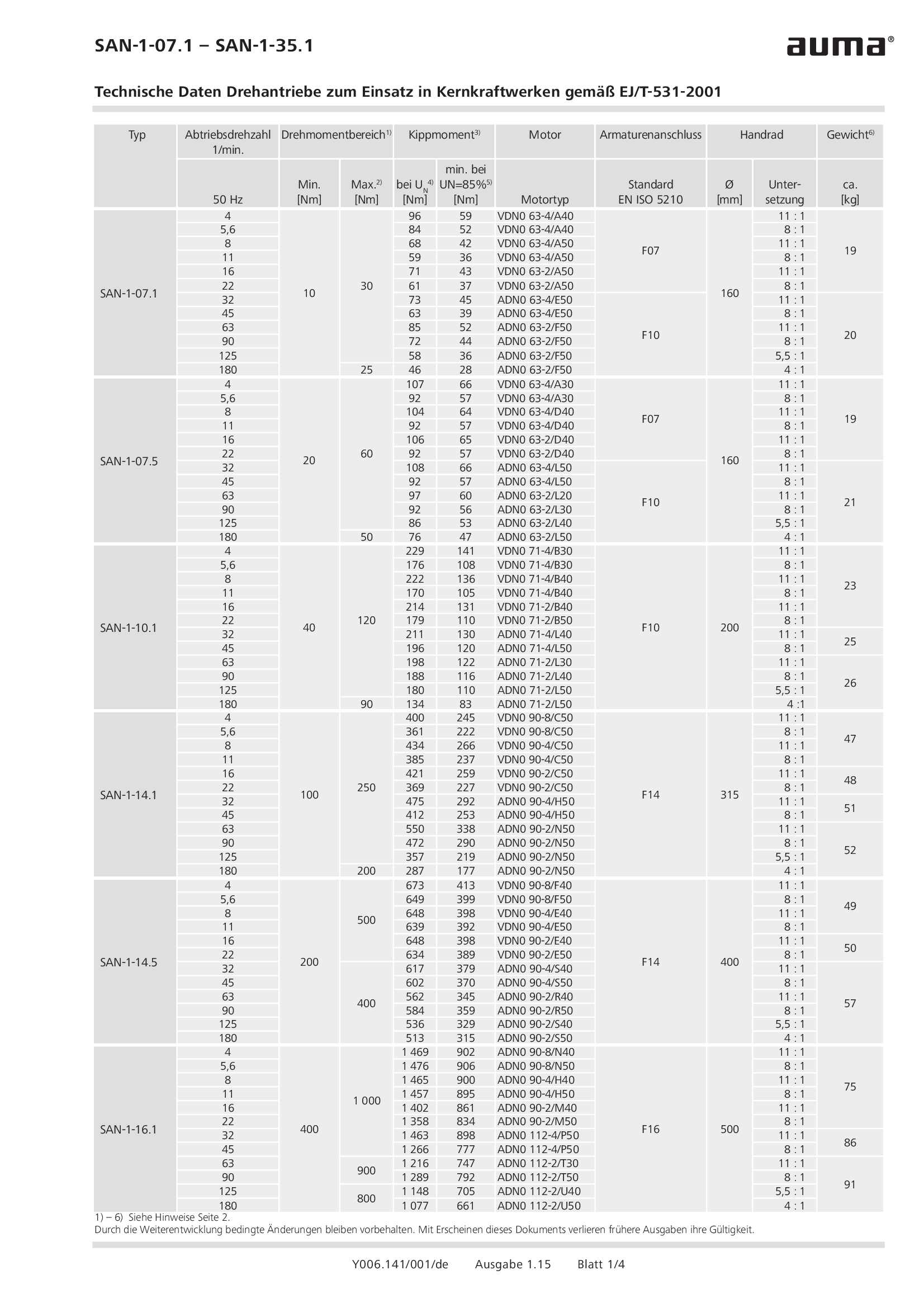
Multi-turn actuators SAN-1-07.1 - 35.1 , open-close duty, nuclear power plants, EJ/T-531-2001
Technical data

Multi-turn actuators SAR 07.2 - 14.6, modulating duty, 1-phase AC
Technical data
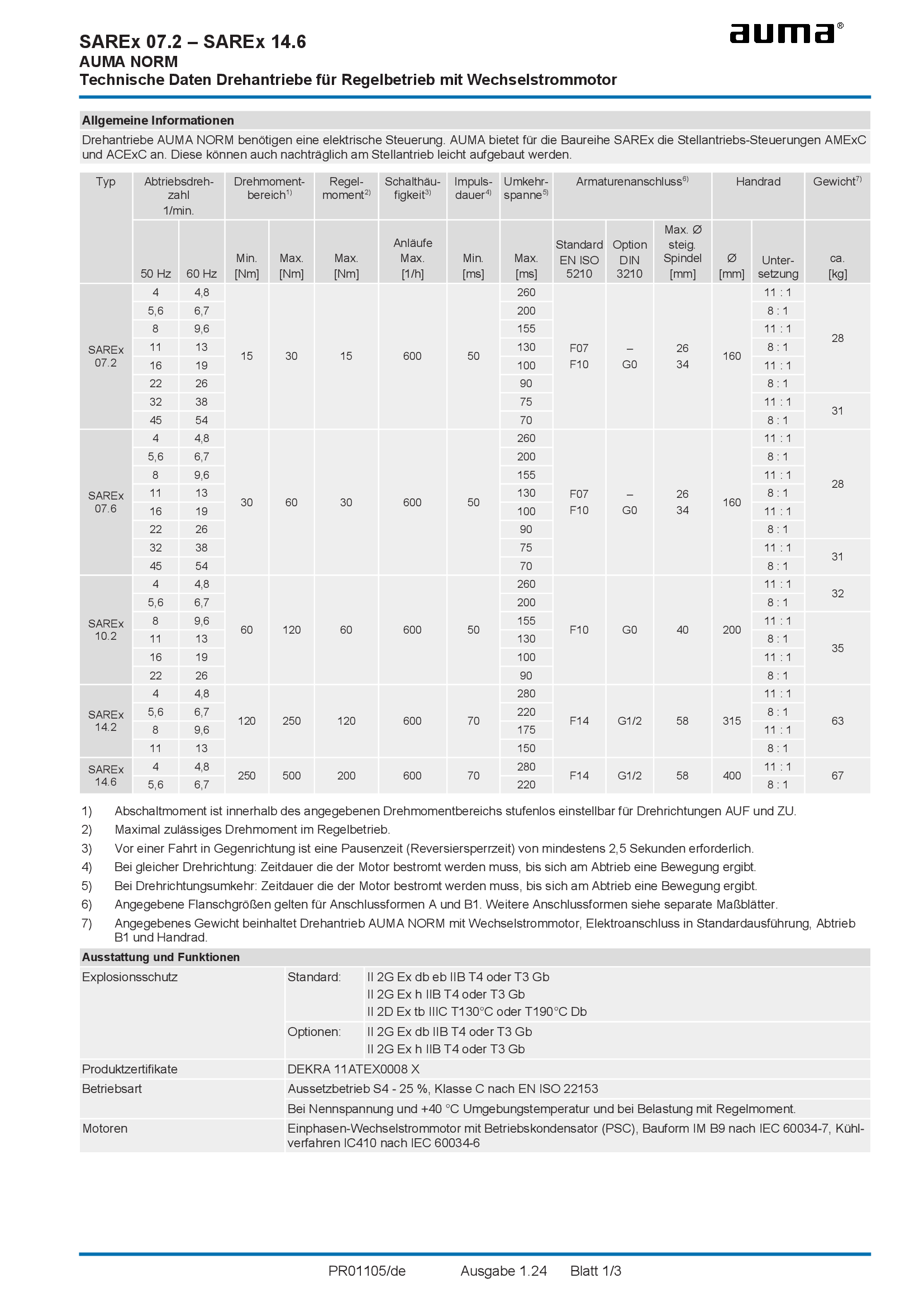
Multi-turn actuators SAREx 07.2 - 14.6, modulating duty, 1-phase AC
Technical data
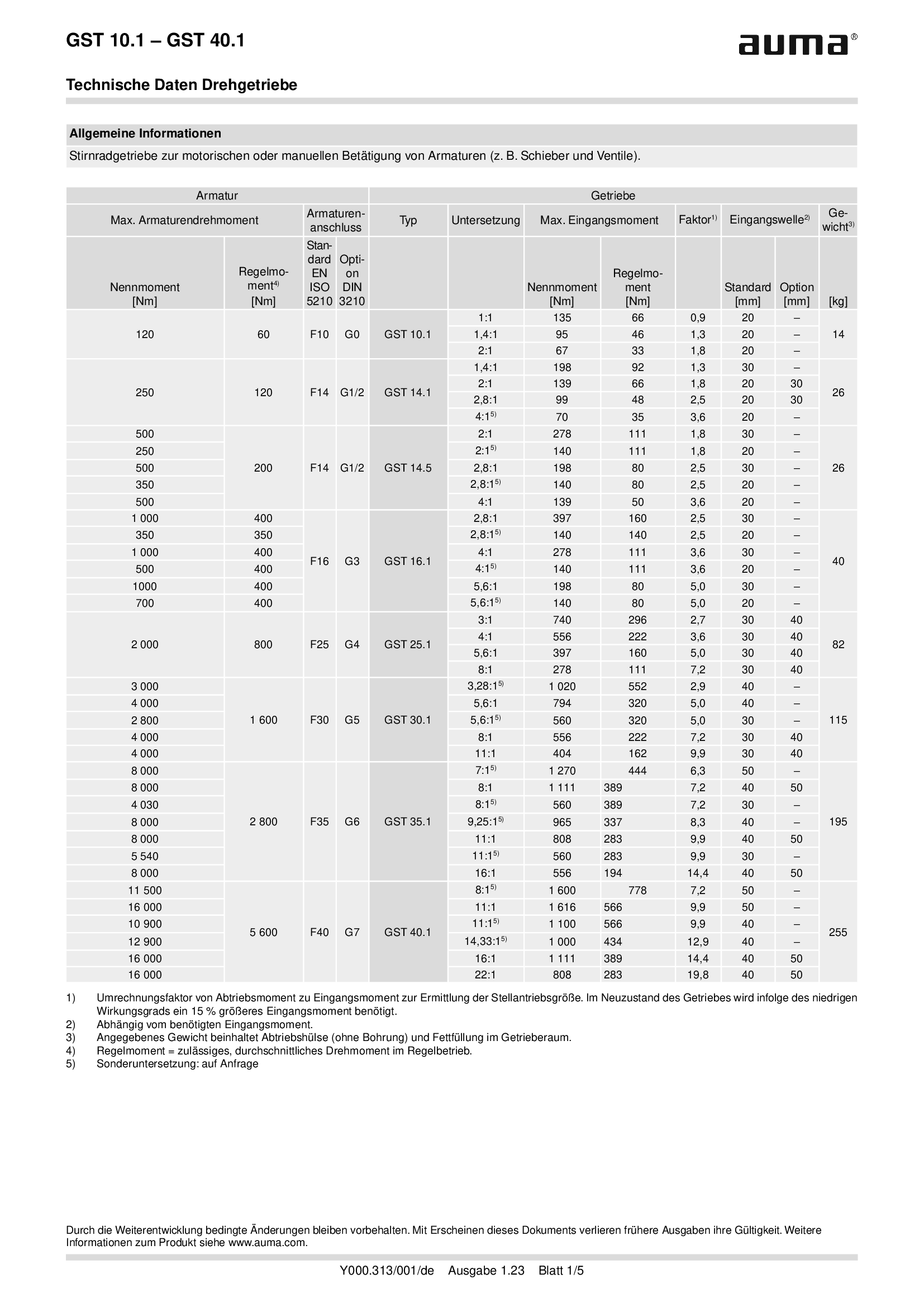
Multi-turn gearboxes GST 10.1 - 40.1
Technical data
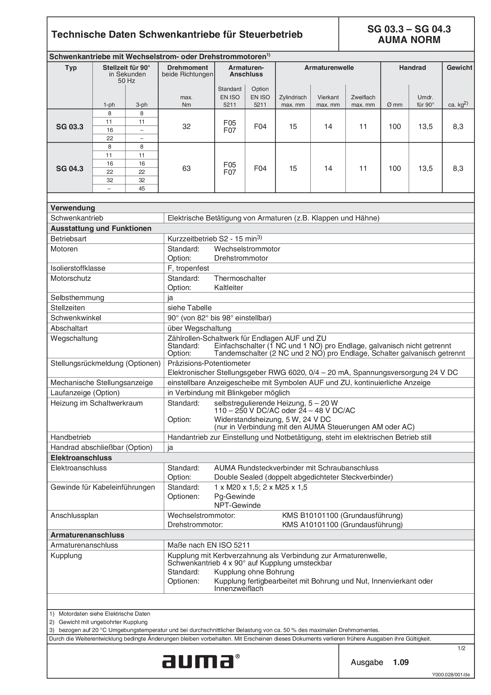
Part-turn actuators SG 03.3 - 04.3, open-close duty, 1-phase AC, 3-phase
Technical data
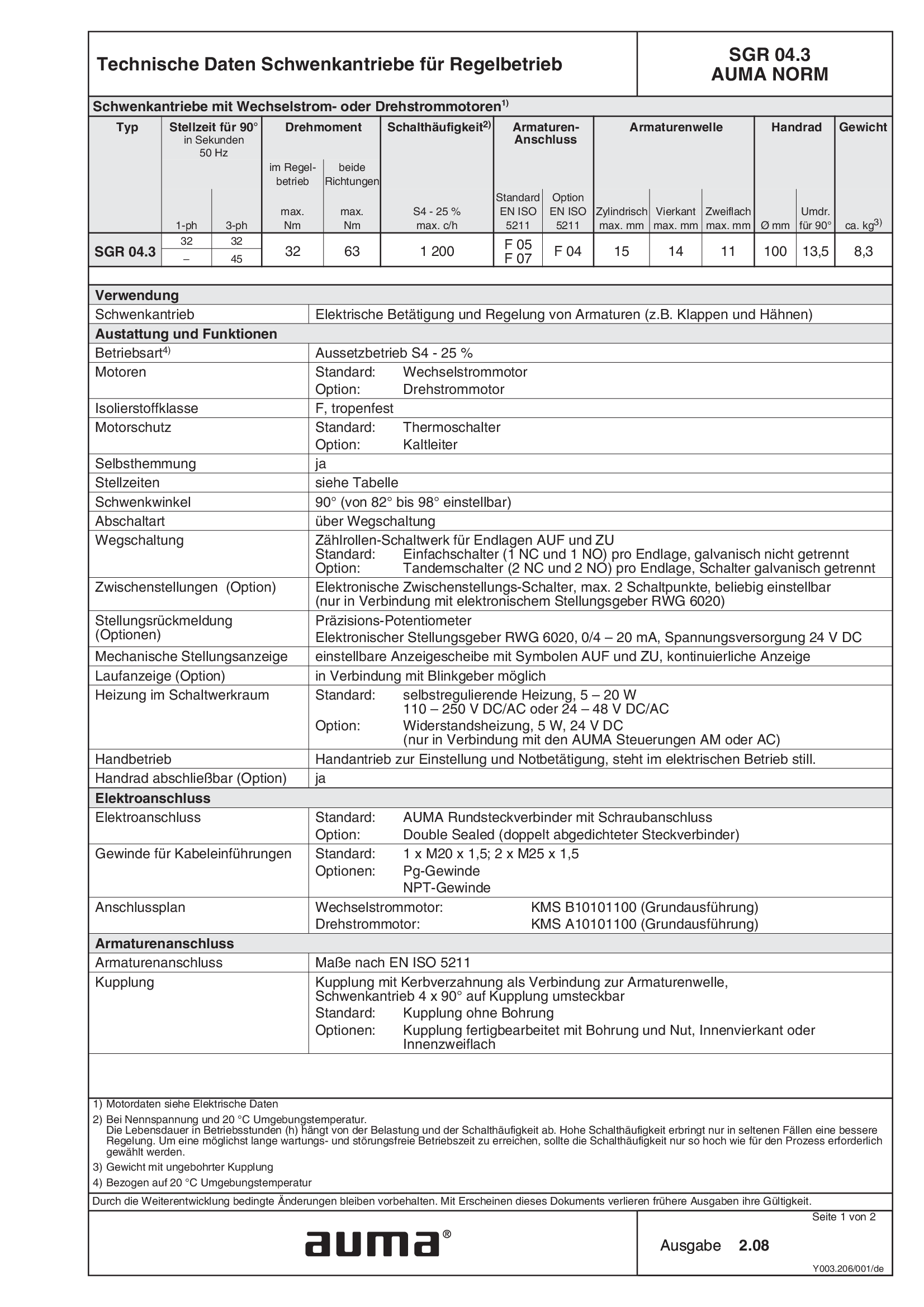
Part-turn actuators SGR 04.3, modulating duty, 1-phase AC, 3-phase
Technical data
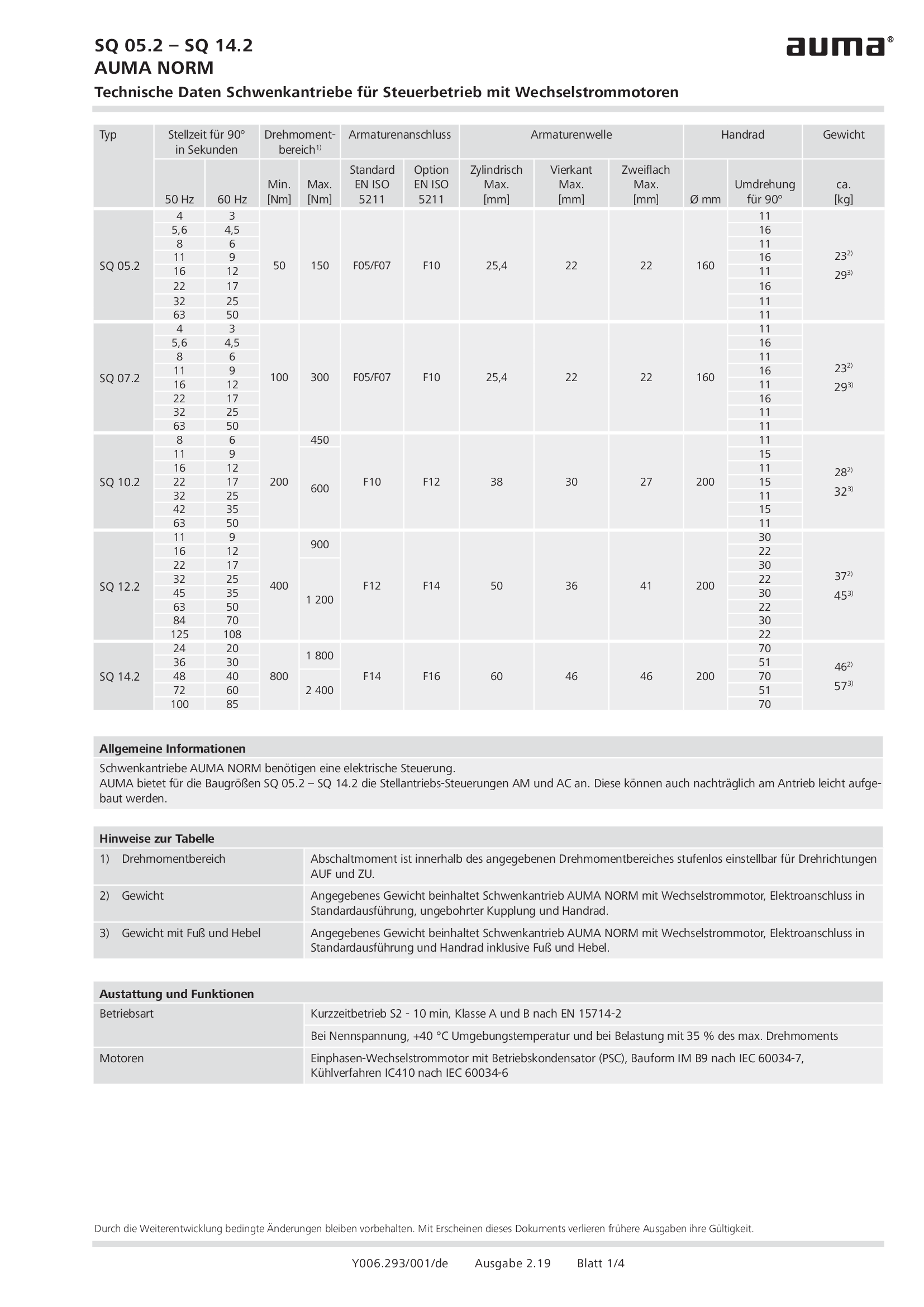
Part-turn actuators SQ 05.2 - 14.2, open-close duty, 1-phase AC
Technical data
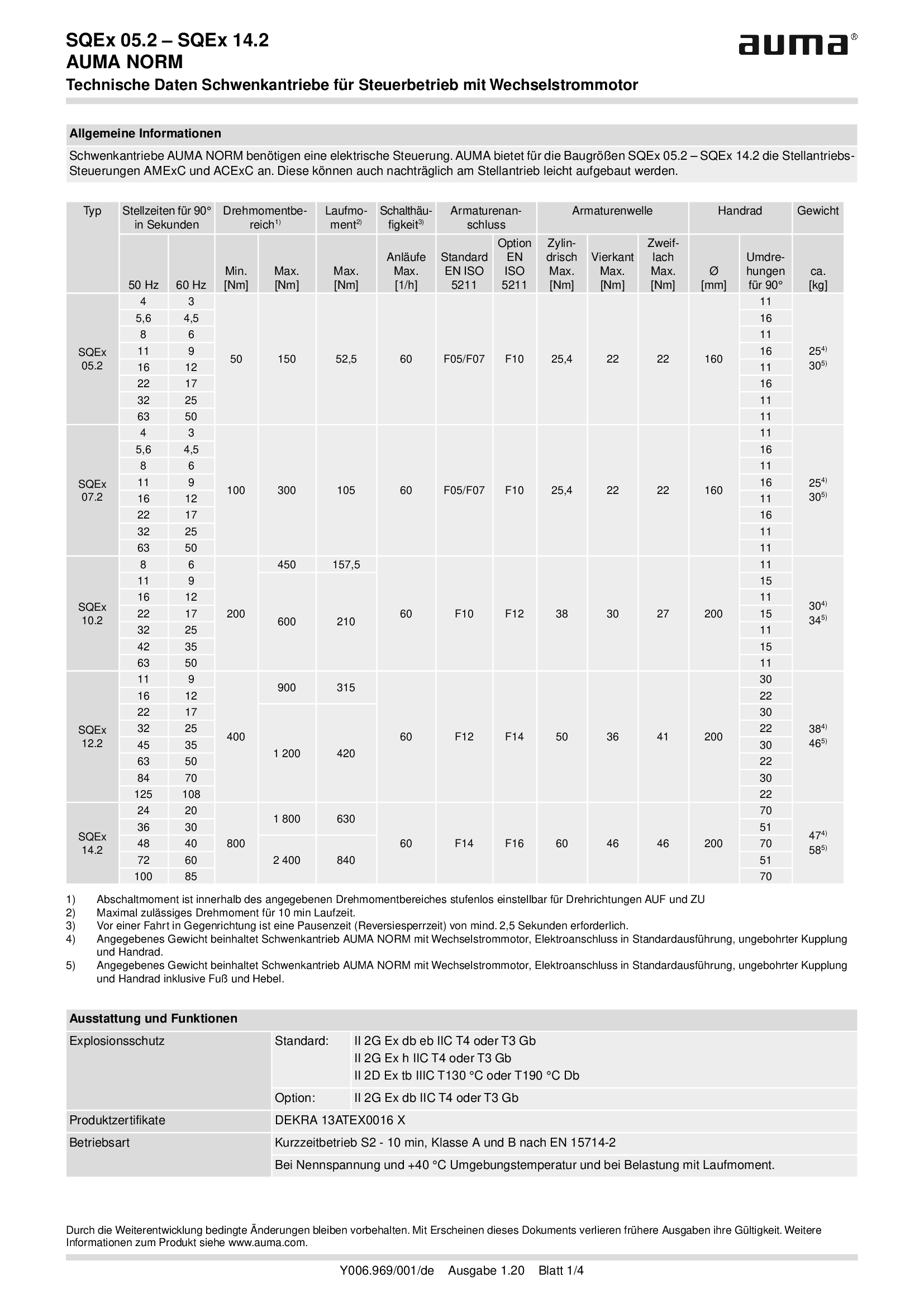
Part-turn actuators SQEx 05.2 - 14.2, open-close duty, 1-phase AC
Technical data

Part-turn actuators SQR 05.2 - 14.2, modulating duty, 1-phase AC
Technical data

Part-turn actuators SQREx 05.2 - 14.2, modulating duty, 1-phase AC
Technical data
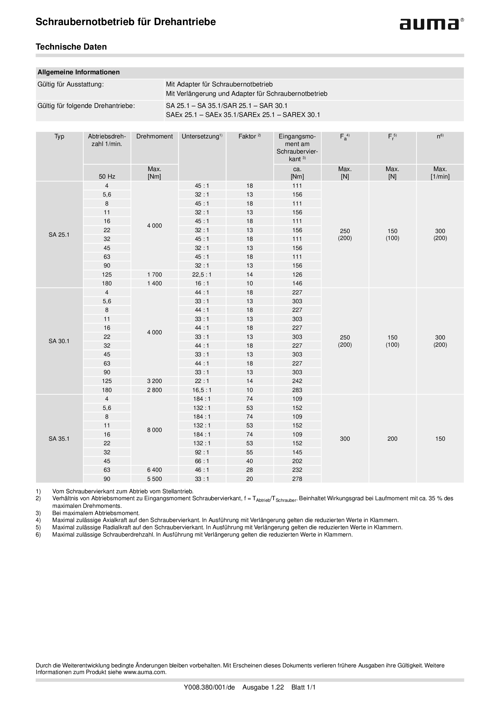
Power tool for emergency operation for multi-turn actuators SA .1
Technical data
Technical description
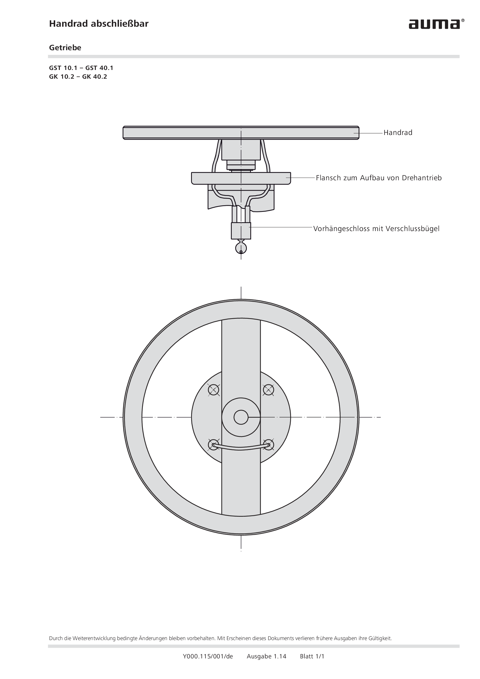
Handwheel lockable gearboxes GST 10.1 – GST 40.1, GK 10.2 – GK 40.2
Technical description
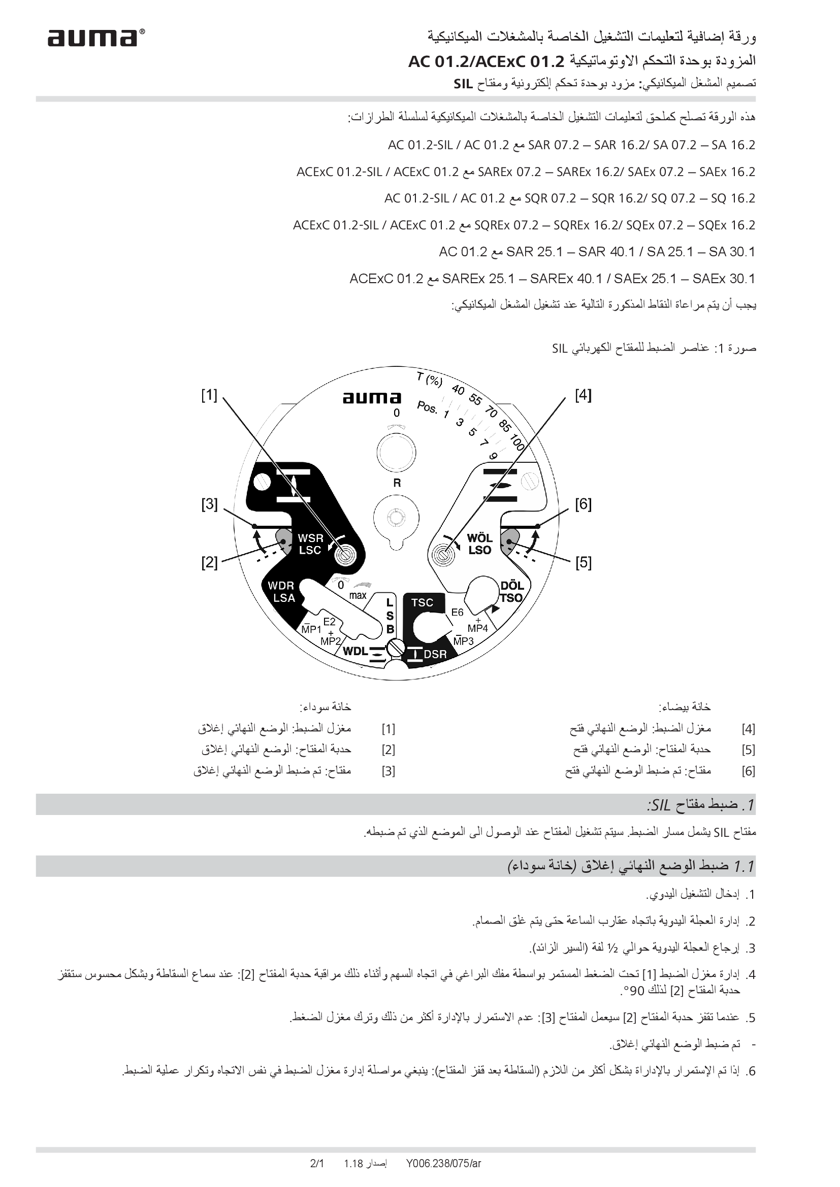
Supplement AUMATIC AC 01.2/ACExC 01.2, version actuators: with elektronic control unit (MWG) and SIL limit switching
Technical description
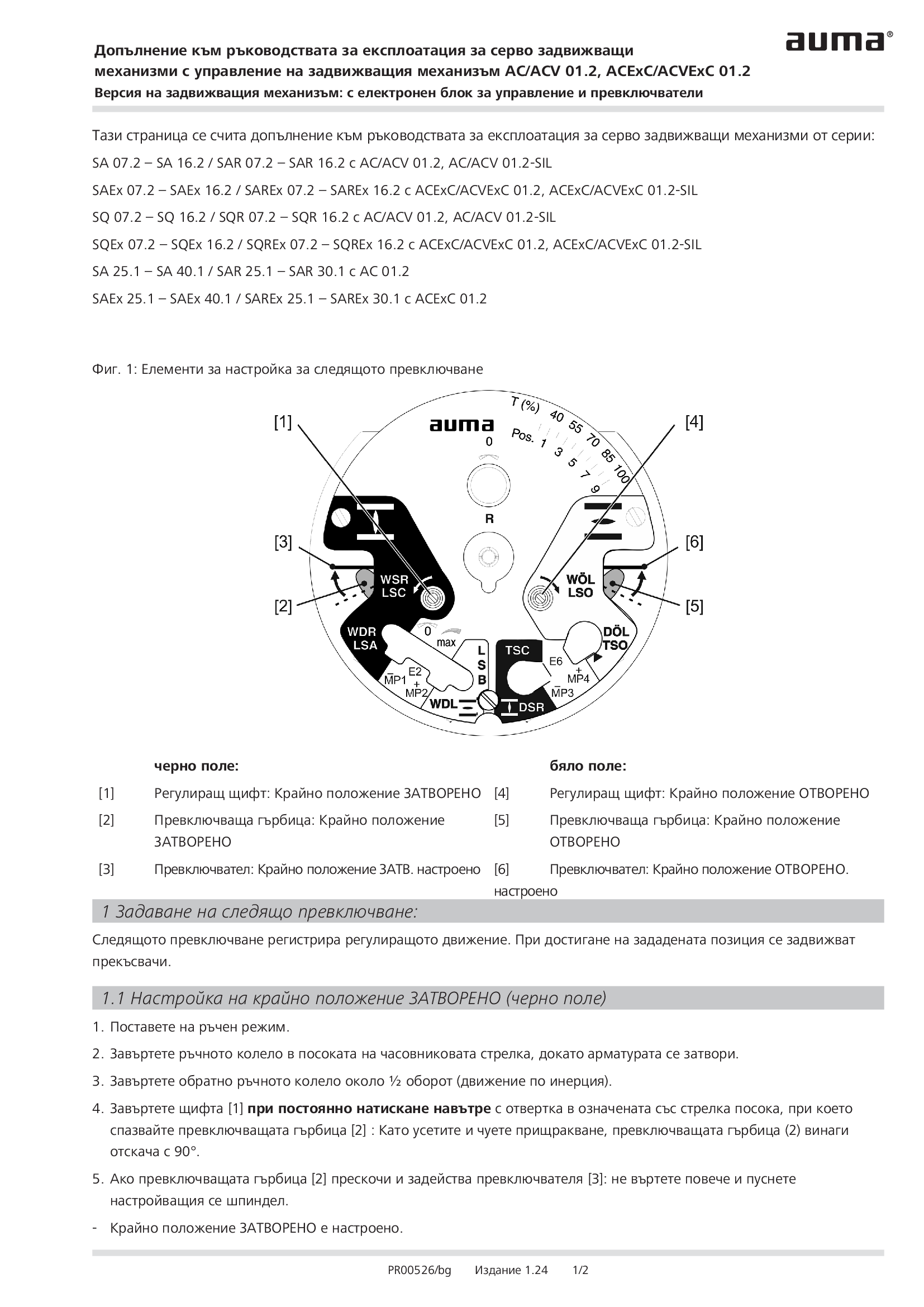
Supplement AUMATIC AC 01.2/ACExC 01.2, version actuators: with elektronic control unit (MWG) and limit switching
Technical description
Wiring diagram

AV1: AUMATIC ACV 01.2 position feedback signal 0/4 – 20 mA (potentiometer in actuator), basic version, CLOSE, OPEN, STOP, EMERGENCY (24 V DC), 6 programmable output contacts, 1-ph; 220 V - 240 V
Wiring diagram

AV1: AUMATIC ACVExC 01.2 position feedback signal 0/4 - 20 mA (potentiometer in actuator), basic version, CLOSE, OPEN, STOP, EMERGENCY (24 V DC), 6 programmable output contacts, 1-ph; 220 V -240 V
Wiring diagram

AV1N: AUMATIC ACV 01.2 position/torque feedback signal 0/4 – 20 mA (MWG in actuator), CLOSE, OPEN, STOP, EMERGENCY (24 V DC), 6 programmable output contacts, 1-ph; 220 V - 240 V
Wiring diagram

AV1N: AUMATIC ACVExC 01.2 position/torque feedback signal 0/4 - 20 mA (MWG in actuator), CLOSE, OPEN, STOP, EMERGENCY (24 V DC), 6 programmable output contacts, 1-ph 220 V - 240 V
Wiring diagram

AV2: AUMATIC ACV 01.2 positioner and position feedback signal 0/4 – 20 mA (potentiometer in actuator), CLOSE, OPEN, STOP, EMERGENCY (24 V DC), 6 programmable output contacts, 1-ph; 220 V - 240 V
Wiring diagram

AV2: AUMATIC ACV 01.2 positioner and position/torque feedback signal 0/4 – 20 mA (MWG in actuator), MODE, CLOSE, OPEN, STOP, EMERGENCY (24 V DC), setpoint (0/4 – 20 mA), 6 programmable output contacts, 1-ph; 220 V - 240 V
Wiring diagram

AV2: AUMATIC ACVExC 01.2 positioner and position feedback signal 0/4 - 20 mA (potentiometer in actuator), CLOSE, OPEN, STOP, EMERGENCY (24 V DC), 6 programmable output contacts, 1-ph; 220 V -240 V
Wiring diagram

AV2DP: AUMATIC ACV 01.2 position feedback (potentiometer in actuator), basic version, Profibus, 1-ph; 220 V - 240 V
Wiring diagram

AV2DP: AUMATIC ACVExC 01.2 position feedback (potentiometer in actuator), basic version, Profibus, 1-ph; 220 V - 240 V
Wiring diagram

AV2FF: AUMATIC ACV 01.2 position feedback (potentiometer in actuator), basic version, Foundation Fieldbus FF, 1-ph; 220 V - 240 V
Wiring diagram

AV2FF: AUMATIC ACVExC 01.2 position feedback (potentiometer in actuator), basic version, Foundation Fieldbus FF, 1-ph; 220 V - 240 V
Wiring diagram

AV2HRT: AUMATIC AC 01.2 position feedback (potentiometer in actuator), basic version, HART actuator, 1-ph; 220 V - 240 V
Wiring diagram

AV2HRT: AUMATIC ACV 01.2 position feedback (potentiometer in actuator), basic version, HART actuator, 1-ph; 220 V - 240 V
Wiring diagram

AV2HRT: AUMATIC ACVExC 01.2 position feedback (potentiometer in actuator), basic version, HART, 1-ph; 220 V - 240 V
Wiring diagram

AV2HRTCO: AUMATIC ACV 01.2 position feedback (potentiometer in actuator), basic version, HART Current Output, 1-ph; 220 V - 240 V
Wiring diagram

AV2HRTCO: AUMATIC ACVExC 01.2 position feedback (potentiometer in actuator), basic version, HART Current Output, 1-ph; 220 V - 240 V
Wiring diagram

AV2MB: AUMATIC ACV 01.2 position feedback signal (potentiometer in actuator), basic version, Modbus, 1-ph; 220 V- 240 V
Wiring diagram

AV2MB: AUMATIC ACVExC 01.2 position feedback (potentiometer in actuator), basic version, Modbus RTU, 1-ph; 220 V - 240 V
Wiring diagram

AV2MBTCP: AUMATIC ACV 01.2 position feedback (potentiometer in actuator), basic version, Modbus TCP/IP, 1-ph; 220 V - 240 V
Wiring diagram

AV2MBTCP: AUMATIC ACVExC 01.2 position feedback (ptentiometer in actuator), basic version Modbus TCP/IP, 1-ph; 220 V - 240 V
Wiring diagram

AV2N: AUMATIC ACVExC 01.2 positioner and position/torque feedback signal 0/4 - 20 mA (MWG in actuator), MODE, CLOSE, OPEN, STOP, EMERGENCY (24 V DC), setpoint (0/4 - 20 mA), 6 programmable output contacts, 1-ph 220 V - 240 V
Wiring diagram

AV2NDP: AUMATIC ACV 01.2 position/torque feedback (MWG in actuator), Profibus, 1-ph; 220 V - 240 V
Wiring diagram

AV2NDP: AUMATIC ACVExC 01.2 position/torque feedback (MWG in actuator), Profibus, 1-ph; 220 V - 240 V
Wiring diagram

AV2NFF: AUMATIC ACV 01.2 position feedback/torque signal (potentiometer in actuator), Foundation Fieldbus FF, 1 ph; 220 V - 240 V
Wiring diagram

AV2NFF: AUMATIC ACVExC 01.2 position/torque feedback (MWG in actuator), Foundation Fieldbus FF, 1-ph; 220 V - 480 V
Wiring diagram

AV2NHRT: AUMATIC ACV 01.2 position/torque feedback (MWG in actuator), HART actuator, 1-ph; 220 V - 240 V
Wiring diagram

AV2NHRT: AUMATIC ACVExC 01.2 position/torque feedback (MWG in actuator), HART, 1-ph; 220 V - 240 V
Wiring diagram

AV2NHRTCO: AUMATIC ACV 01.2 position/torque feedback (MWG in actuator), HART Current Output, 1-ph; 220 V - 240 V
Wiring diagram

AV2NHRTCO: AUMATIC ACVExC 01.2 position/torque feedback (MWG in actuator), HART Current Output, 1-ph; 220 V - 240 V
Wiring diagram

AV2NMB: AUMATIC ACV 01.2 position/torque feedback (MWG in actuator), Modbus, 1-ph; 220 V- 240 V
Wiring diagram

AV2NMB: AUMATIC ACVExC 01.2 position/torque feedback (MWG in actuator), Modbus RTU, 1-ph; 220 V - 240 V
Wiring diagram

AV2NMBTCP: AUMATIC ACV 01.2 position/torque feedback (MWG in actuator), Modbus TCP/IP, 1-ph; 220 V - 240 V
Wiring diagram

AV2NMBTCP: AUMATIC ACVExC 01.2 position/torque feedback (MWG in actuator), Modbus TCP/IP, 1-ph; 220 V - 240 V
Wiring diagram

AV2NPN: AUMATIC ACV 01.2 position/torque feedback (MWG in actuator), Profinet, 1-ph; 220 V - 240 V
Wiring diagram

AV2PN: AUMATIC ACV 01.2 position feedback (potentiometer in actuator), Profinet, 1-ph; 220 V - 240 V
Wiring diagram

AV4DP: AUMATIC ACV 01.2 positioner and position feedback signal 0/4 – 20 mA (potentiometer in actuator), basic version, MODE, CLOSE, OPEN, STOP, EMERGENCY, I/O (24 V DC), 6 programmable output contacts, Profibus, 1-ph; 220 V - 240 V
Wiring diagram

AV4DP: AUMATIC ACVExC 01.2 positioner und position feedback signal 0/4 - 20 mA (potentiometer in actuator), basic version, MODE, CLOSE, OPEN, STOP, EMERGENCY, I/O ( 24 V DC), 6 programmable output contacts, Profibus DP, 1-ph; 220 V - 240 V
Wiring diagram

AV4FF: AUMATIC ACExC 01.2 positioner and position feedback signal 0/4 - 20 mA (potentiometer in actuator), basic version, MODE, CLOSE, OPEN, STOP, EMERGENCY, I/O ( 24 V DC), 6 programmable output contacts, Foundation Fieldbus FF, 1-ph; 220 V - 240 V
Wiring diagram

AV4FF: AUMATIC ACV 01.2 positioner and position feedback signal 0/4 – 20 mA (potentiometer in actuator), basic version, MODE, CLOSE, OPEN, STOP, EMERGENCY, I/O (24 V DC), 6 programmable output contacts, Foundation Fieldbus, 1-ph; 220 V - 240 V
Wiring diagram

AV4HRT: AUMATIC ACV 01.2 positioner and position feedback signal 0/4 – 20 mA (potentiometer in actuator), basic version, MODE, CLOSE, OPEN, STOP, EMERGENCY, I/O (24 V DC), 6 programmable output contacts, HART, 1-ph; 220 V - 240 V
Wiring diagram

AV4HRT: AUMATIC ACVExC 01.2 positioner and position feedback signal 0/4 - 20 mA (potentiometer in actuator), basic version, MODE, CLOSE, OPEN, STOP, EMERGENCY; I/O (24 V DC), 6 programmable output contacts, HART, 1-ph; 220 V - 240 V
Wiring diagram

AV4HRTCO: AUMATIC ACV 01.2 positioner and position feedback signal 0/4 – 20 mA (potentiometer in actuator), basic version, MODE, CLOSE, OPEN, STOP, EMERGENCY, I/O (24 V DC), 6 programmable output contacts, HART, 1-ph; 220 V - 240 V
Wiring diagram

AV4HRTCO: AUMATIC ACVExC 01.2 positioner and position feedback signal 0/4 - 20 mA (potentiometer in actuator), basic version, MODE, CLOSE, OPEN, STOP, EMERGENCY, I/O (24 V DC), 6 programmable output contacts, HART Current output, 1-ph; 220 V - 240 V
Wiring diagram

AV4MB: AUMATIC ACV 01.2 positioner and position feedback signal 0/4 – 20 mA (potentiometer in actuator), basic version, MODE, CLOSE, OPEN, STOP, EMERGENCY, I/O (24 V DC), 6 programmable output contacts, Modbus, 1-ph; 220 V - 240 V
Wiring diagram

AV4MB: AUMATIC ACVExC 01.2 positionier and position feedback signal 0/4 - 20 mA (potentiometer in actuator), basic version, MODE, CLOSE, OPEN, STOP, EMERGENCY, I/O (24 V DC), 6 programmable output contacts, Modbus RTU, 1-ph; 220 V - 240 V
Wiring diagram

AV4MBTCP: AUMATIC ACV 01.2 positioner and position feedback signal 0/4 – 20 mA (potentiometer in actuator), basic version, MODE, CLOSE, OPEN, STOP, EMERGENCY, I/O (24 V DC), 6 programmable output contacts, Modbus TCP/IP, 1-ph; 220 V - 240 V
Wiring diagram

AV4MBTCP: AUMATIC ACVExC 01.2 positioner and position feedbak signal 0/4 - 20 mA (potentiometer in actuator), basic version, MODE, CLOSE, OPEN, STOP, EMERGENCY, I/O (24 V DC), 6 programmable output contacts, Modbus TCP/IP 1-ph; 220 V - 240 V
Wiring diagram

AV4NDP: AUMATIC ACV 01.2 positioner and position/torque feedback signal 0/4 – 20 mA (MWG in actuator), MODE, CLOSE, OPEN, STOP, EMERGENCY, I/O (24 V DC), 6 programmable output contacts, Profibus DP, 1-ph; 220 V - 240 V
Wiring diagram

AV4NDP: AUMATIC ACVExC 01.2 positioner and position/torque feedback signal 0/4 - 20 mA (MWG in actuator), MODE, CLOSE, OPEN, STOP, EMERGENCY, I/O (24 V DC), 6 programmable output contacts, Profibus DP, 1-ph; 220 V - 240 V
Wiring diagram

AV4NFF: AUMATIC ACV 01.2 positioner and position/torque feedback signal 0/4 – 20 mA (MWG in actuator), MODE, CLOSE, OPEN, STOP, EMERGENCY, I/O (24 V DC), 6 programmable output contacts, Foundation Fieldbus FF, 1-ph; 220 V - 240 V
Wiring diagram

AV4NFF: AUMATIC ACVExC 01.2 positioner and position/torque feedback signal 0/4 - 20 mA (MWG in actuator), MODE, CLOSE, OPEN, STOP, EMERGENCY, I/O (224 V DC), 6 programmable output contacts, Foundation Fieldbus FF, 1-ph; 220 V - 240 V
Wiring diagram

AV4NHRT: AUMATIC ACVExC 01.2 positioner and position/torque feedback signal 0/4 - 20 mA (MWG in actuator), MODE, CLOSE, OPEN, STOP, EMERGENCY, I/O ( 24 V DC), 6 programmable output contacts, HART, 1-ph; 220 V - 240 V
Wiring diagram

AV4NHRTCO: AUMATIC ACVExC 01.2 position/torque feedback (MWG in acutator), MODE, CLOSE, OPEN, STOP, EMERGENCY, I/O (24 V DC), 6 programmabel output contacts, HART Current output, 1-ph; 220 V - 240 V
Wiring diagram

AV4NMB: AUMATIC ACV 01.2 positioner and position/torque feedback signal 0/4 – 20 mA (MWG in actuator), MODE, CLOSE, OPEN, STOP, EMERGENCY, I/O (24 V DC), 6 programmable output contacts, Modbus RTU, 1-ph; 220 V - 240 V
Wiring diagram

AV4NMB: AUMATIC ACVExC 01.2 positioner and position/torque feedback signal 0/4 - 20 mA (MWG in actuator), MODE, CLOSE, OPEN, STOP, EMERGENCY, I/O (24 V DC), 6 programmable output contacts, Modbus RTU, 1-ph; 220 V - 240 V
Wiring diagram

AV4NMBTCP: AUMATIC ACV 01.2 positioner and position/torque feedback signal 0/4 – 20 mA (MWG in actuator), MODE, CLOSE, OPEN, STOP, EMERGENCY, I/O (24 V DC), 6 programmable output contacts, Modbus TCP/IP, 1-ph; 220 V - 240 V
Wiring diagram

AV4NMBTCP: AUMATIC ACVExC 01.2 positioner and position/torque feedback signal 0/4 - 20 mA (MWG in actuator), MODE, CLOSE, OPEN, STOP, EMERGENCY, I/O (24 V DC), 6 programmable output contacts, Modbus TCP/IP, 1-ph; 220 V - 240 V
Wiring diagram

AV4NPN: AUMATIC ACV 01.2 positioner and position/torque feedback signal 0/4 – 20 mA (MWG in actuator),Profinet, 1-ph; 220 V - 240 V
Wiring diagram

AV4PN: ACV 01.2 positioner and position feedback signal 0/4 – 20 mA (potentiometer in actuator), Profinet,1-ph; 220 V - 240 V
Wiring diagram

AV4PN: AUMATIC ACV 01.2 positioner and position feedback signal 0/4 – 20 mA (potentiometer in actuator), Profinet,1-ph; 220 V - 240 V
Wiring diagram

AV5N: AUMATIC ACV 01.2 position/torque feedback signal 0/4 – 20 mA (MWG in actuator), CLOSE, OPEN, STOP, EMERGENCY, INTERLOCK CLOSE, INTERLOCK OPEN, 6 programmable output contacts, 1-ph; 220 V - 240 V
Wiring diagram

AV5N: AUMATIC ACVExC 01.2 position/torque feedback signal 0/4 - 20 mA (MWG in actuator), CLOSE, OPEN, STOP, EMERGENCY INTERLOCK CLOSE, INTERLOCK OPEN, 6 programmable output contacts, 1-ph 220 V - 240 V
Wiring diagram

AVN4HRT: AUMATIC ACV 01.2 positioner and position/torque feedback signal 0/4 – 20 mA (MWG in actuator), MODE, CLOSE, OPEN, STOP, EMERGENCY, I/O (24 V DC), 6 programmable output contacts, HART, 1-ph; 220 V - 240 V
Wiring diagram

AVN4HRTCO: AUMATIC ACV 01.2 position/torque feedback (MWG in actuator), MODE, CLOSE, OPEN, STOP, EMERGENCY, I/O (24 V DC), 6 programmable output contacts, HART Current Output, 1-ph; 220 V - 240 V
Wiring diagram
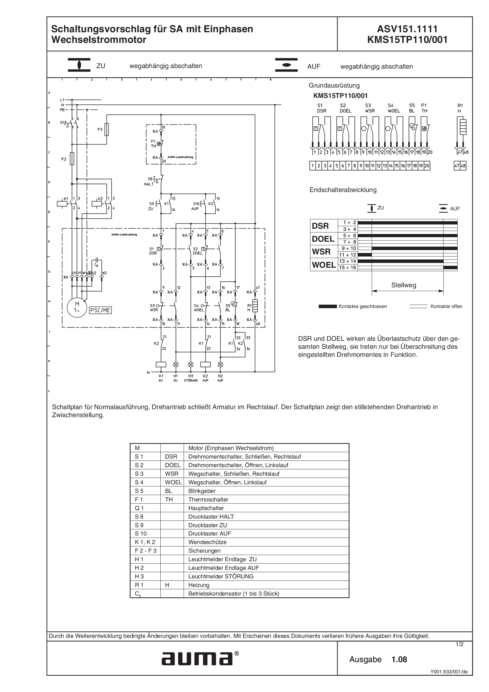
SA.1, 1-ph AC, ASV151.1111 /ASV151.1121 KMS15TP110/001
Wiring diagram
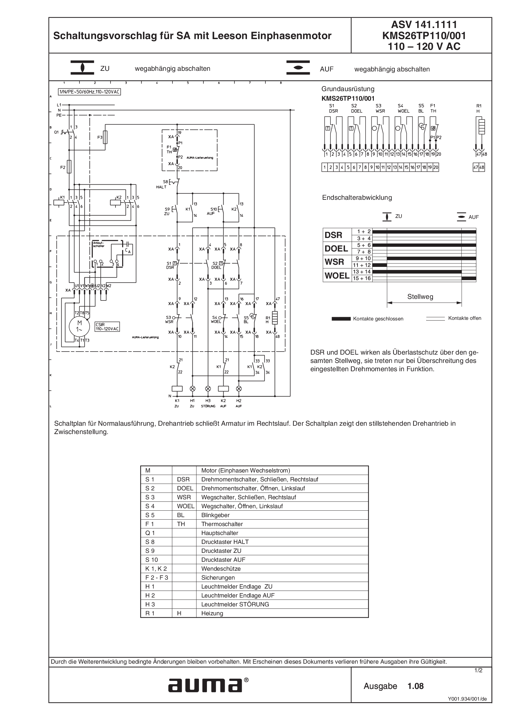
SA.1, 1-ph AC, Leeson motor ASV141.1111 /ASV141.1121 KMS26TP110/001 110 - 120 V AC
Wiring diagram
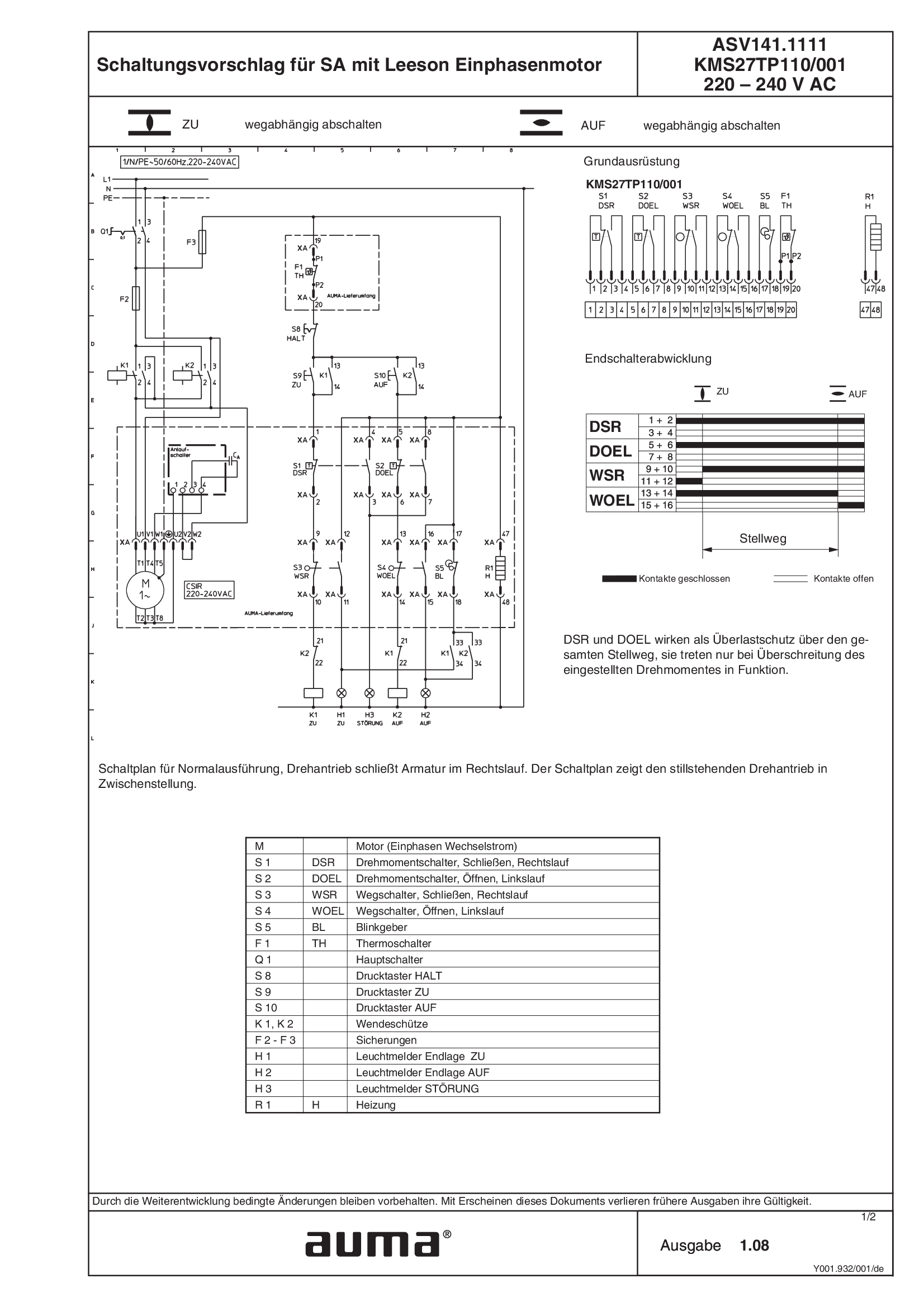
SA.1, 1-ph AC, Leeson motor ASV141.1111 /ASV141.1121 KMS27TP110/001 220 - 240 V AC
Wiring diagram
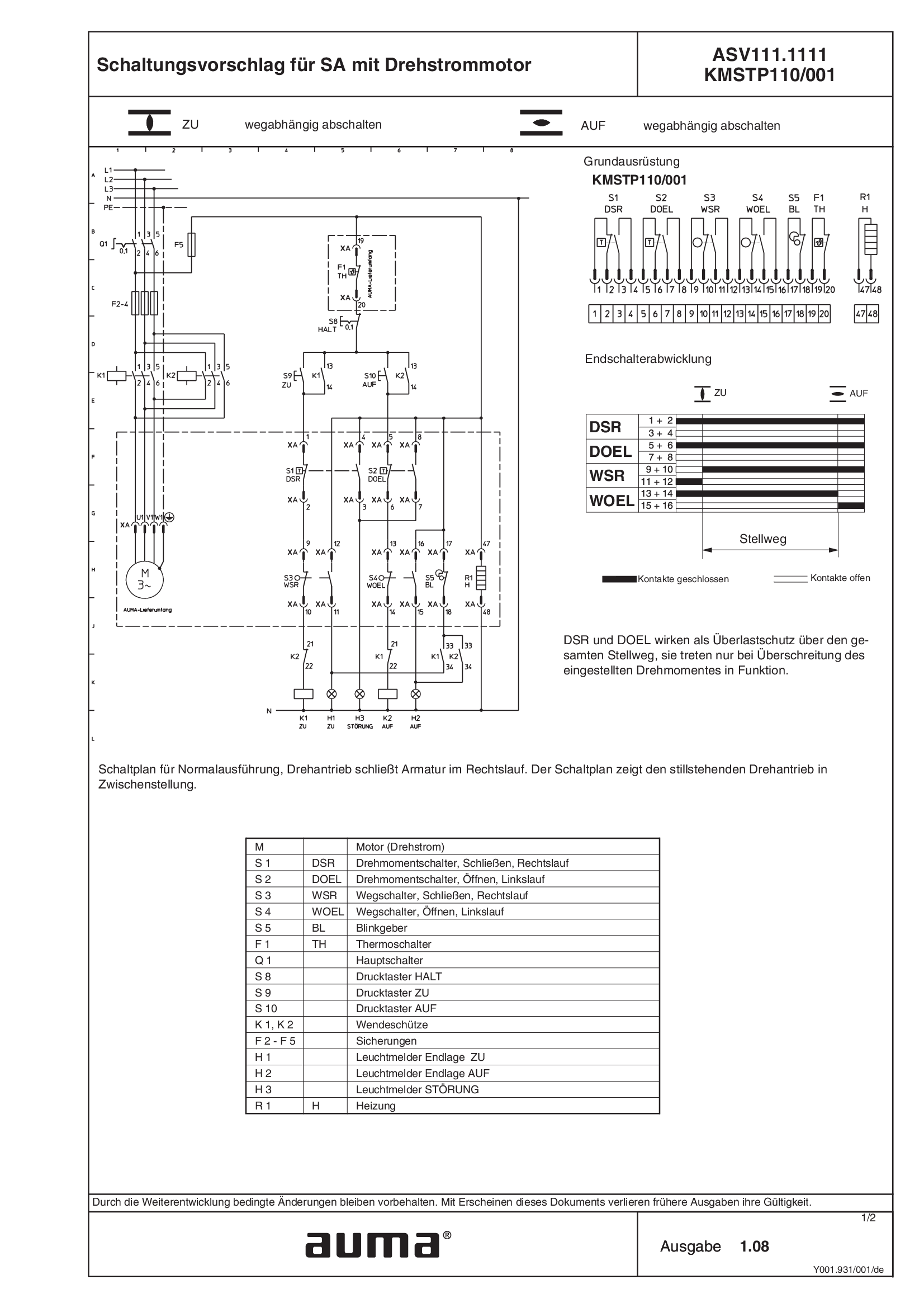
SA.1, 3-ph AC ASV111.1111 /ASV111.1121 KMSTP110/001
Wiring diagram
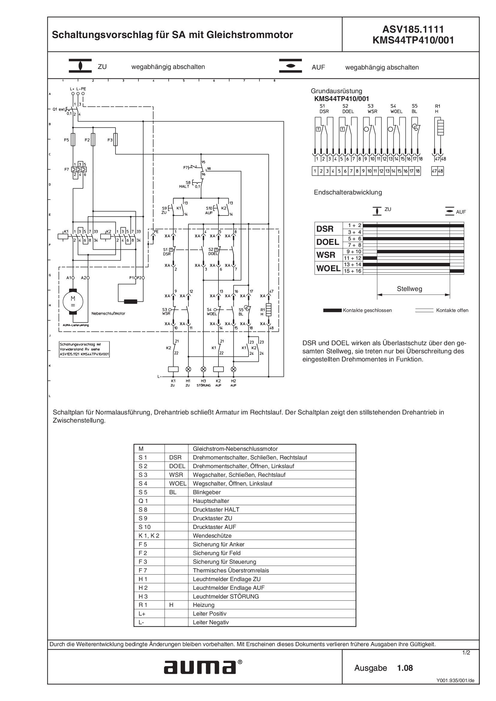
SA.1, DC ASV185.1111 /ASV185.1121 KMSTP410/001
Wiring diagram
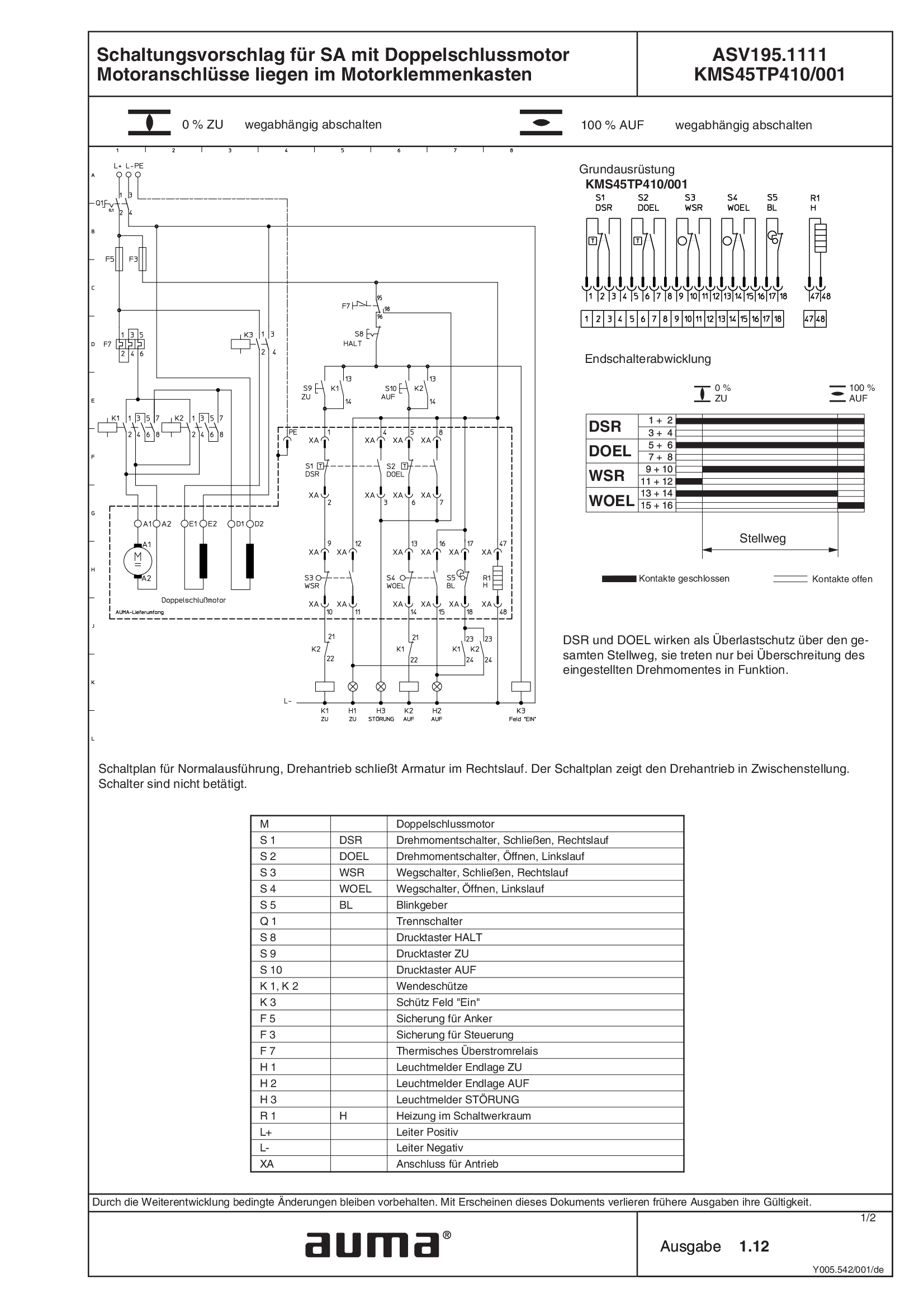
SA.1, DC ASV195.1111/ASV195.1121 KMS45TP410/001, compound motor, motor connections with motor terminal box
Wiring diagram

SA.1, DC ASV195.1111/ASV195.1121 KMS63TP410/001, compound motor, motor connection with plug/socket connector
Wiring diagram
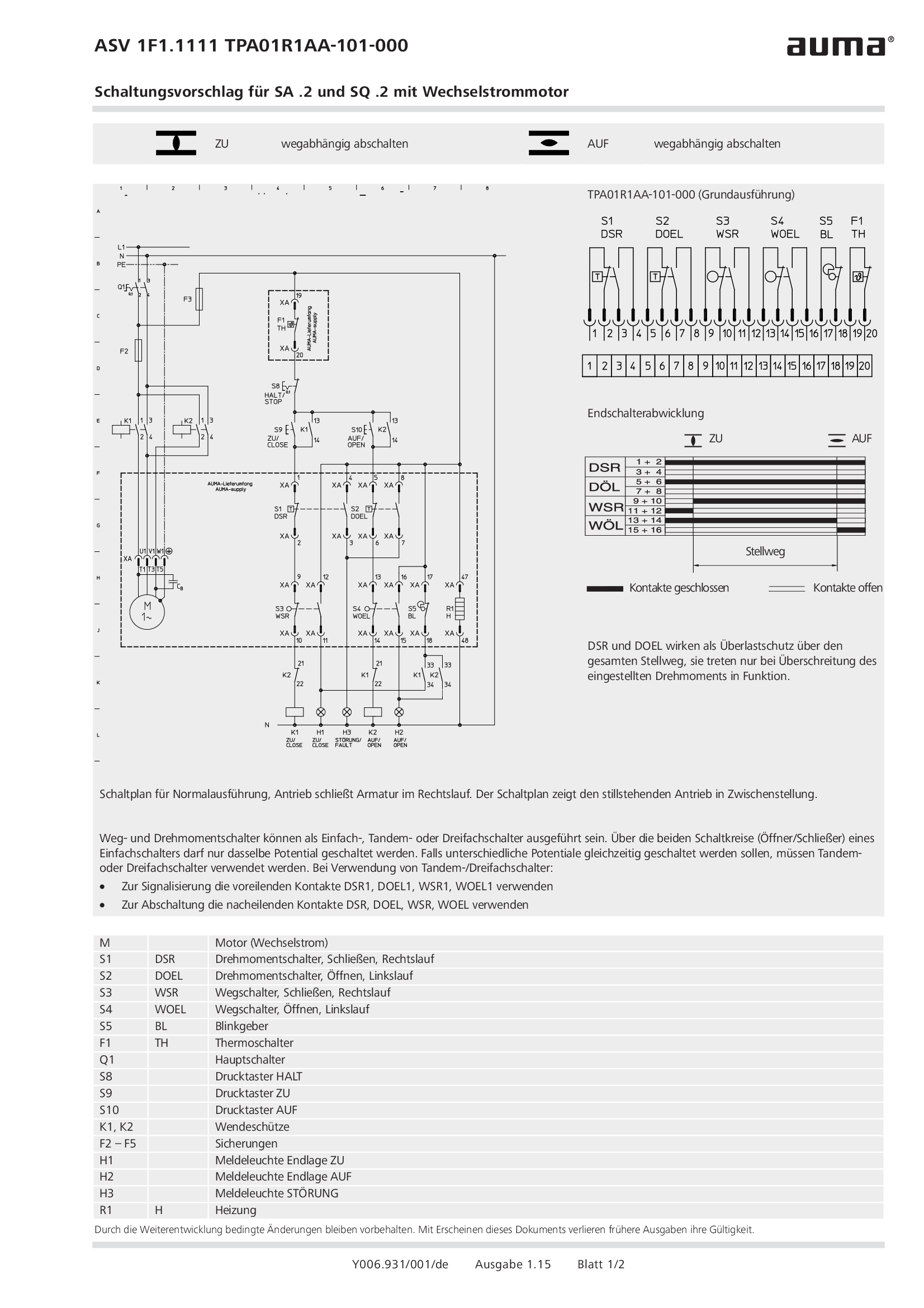
SA.2/SQ.2, 1-ph AC ASV1F1.1111 /ASV1F1.1121 TPA01R1AA-101-000
Wiring diagram
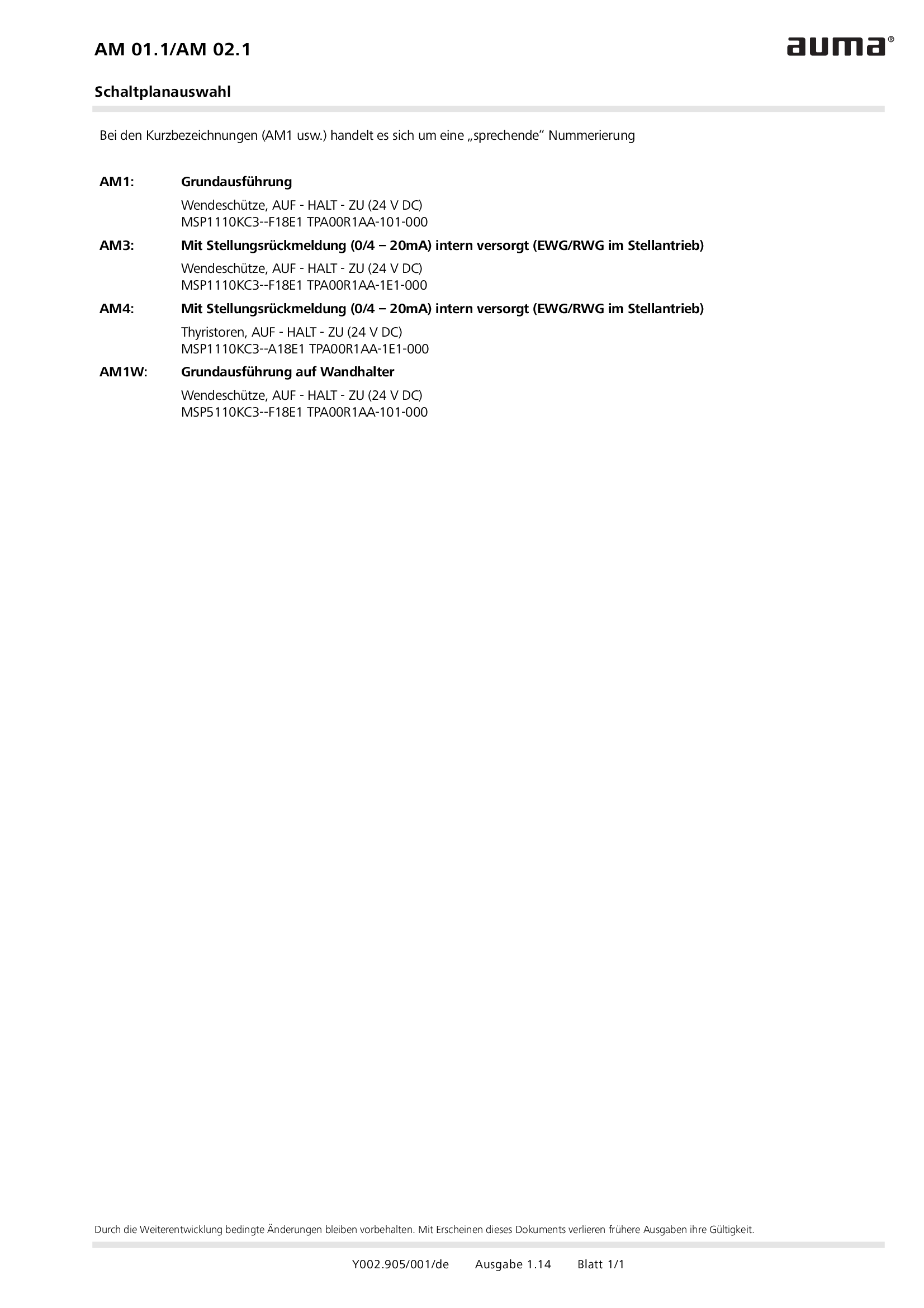
Selection of wiring diagrams for MATIC AM 01.1/AM 02. 1
Wiring diagram


